Download to read offline

![[Safety Precaution]
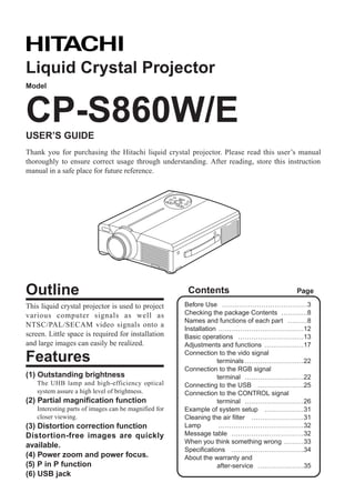
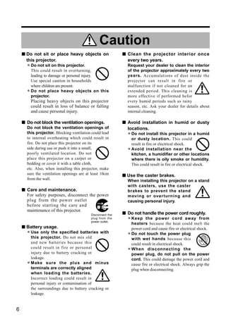
Warning
s If a problem should occur. s Do not insert foreign objects.
• If smoke or a strange odor arise, continued
use could result in fire or electrical shock. In
• Do not insert metal objects etc., of
the ventilation openings,
through
such case, immediately turn off the power this projector or drop such objects
switch and then disconnect the power plug inside because this could result in
from the power outlet. After making sure that fire or electrical shock.
the smoke or odor has stopped, contact your
dealer for repairs. Never attempt to make
• If a foreign object should enter this
projector, immediately turn off the power
repairs yourself because this is dangerous. switch, disconnect the
• Do not use this projector if
there is no image or
power plug from the
power outlet and contact
sound, or if the sound is your dealer.
Disconnect the
distorted. Continued use Disconnect the Continued use could result in plug from the
plug from the
could result in fire or power outlet. fire or electrical shock. Use power outlet.
electrical shock. special caution in households
In such case, immediately turn off the power where children are present.
switch, disconnect the power plug from the
power outlet and contact your dealer. s Do not look through the lens
• If water should enter the inside of this
projector, immediately turn off the power
when the lamp is on.
Never look through the lens when the
switch, disconnect the power plug from the
lamp is on. The powerful light could adversely
power outlet and contact your dealer.
affect vision. Use special caution in households
where children are present.
s Do not install on an unstable surface.
• Do not install this projectorwobbly
unstable surface such as a
on an
s Avoid shock or impact on the projector.
If the projector should fall,
stand or incline because this could
resulting in damage to the
result in the projector falling and
cabinet, immediately turn off
causing injury.
the power switch, disconnect Disconnect the
the power plug from the power plug from the
s Do not open the cabinet. outlet and contact your dealer.
power outlet.
• Never eis high voltage
Ther
open the cabinet. Continued use could result in
fire or electrical shock.
inside which can cause
electrical shock. Do not Do not use
near water. s Do not place this projector in
Contact your dealer for disassemble.
internal inspection, adjustment and a container containng liquid.
repair. Do not place flower vases, flower
pots, cups, cosmetics, liquids
such as water, etc., on top of this projector.
s Do not modify. Spillage could result in fire or electrical shock.
Do not modify this projector because Do not
disassemble.
this could result in fire or electrical shock.
s Use only the indicated power
s Do not use in the bathroom. supply.
Use only the indicated power
Do not use this projector in the
supply. The us eof any other power supply
bathroom because this could result in Do not use near
water. could result in fire or electrical shock.
fire or electrical shock.
4](https://image.slidesharecdn.com/hitachiicp-s860elcdprojectormanual-120321115440-phpapp01/85/Hitachii-cp-s860e-lcd-projector-manual-4-320.jpg)
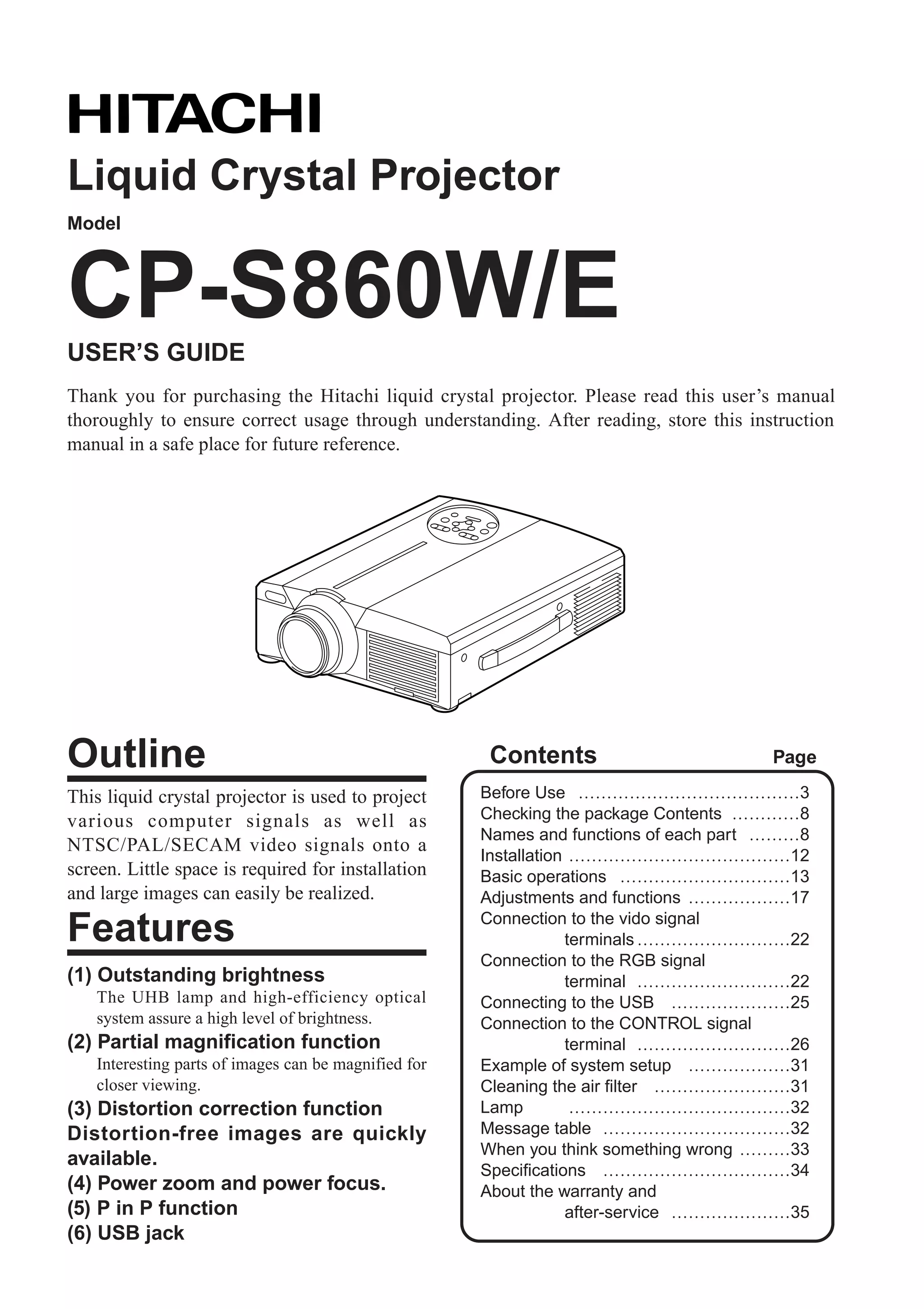
![Caution
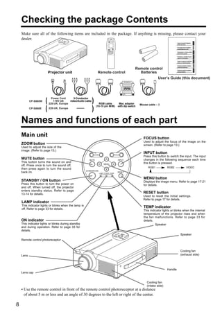
s When the projector is not to be used s Moving the projector.
for an extended period. • When movinglens cover, disconnect
to close the
the projector, be sure
For safety purposes when the
projector is not to be used for an the power plug from the power outlet
extended period because of travel, and disconnect all external Disconnect the
plug from the
etc., always disconnect the power Disconnect the the connections. Failure to do this power outlet.
plug from
plug from the power outlet. Also power outlet. could damage the power cord
close the lens cover to prevent the lens and cause fire or electrical shock.
surface being scratched. Avoid any impact or shock to the projector
because this could result in malfunction.
• When moving this projector outdoors, protect
it from wetting due to rain, etc. If the
projector should become wet, dry it
thoroughly before further use.
Continued use while wet could
result in fire or electrical shock.
[General Cautions]
s Avoid excessively hot locations. s Cabinet care.
Do not place this projector in direct
sunlight or near a hot object such as a
• The cabinet is madeoccur if wiped with a solvent
or paint peeling can
of plastic and discoloration
stove, etc., because the heat could such as benzine, thinner, etc.
have adverse influence on the cabinet
and other parts.
• Before using chemical wipes, be sure to read
and observe the instructions.
• Do not spray volatile substances such as
insect repellent on the cabinet. Also, do not
s Sound volume.
Set the volume at a suitable level to avoid allow long-term close contact with rubber or
bothering other people. It is also better to keep vinyl products because this could result in
the volume level low and close the windows at discoloration, peeling paint, etc.
night to protect the neighborhood environment. • Use a soft cloth to clean the cabinet and
operation panel. When excessively soiled,
dilute a neutral detergent in water, wet and
s Lens care wring out the cloth and afterward wipe with a
Use commercially available lens
dry cloth. Do not apply undiluted detergent
tissue to clean the lens (used to clean
directly to the projector.
cameras, eyeglasses, etc.). Be careful
not to scratch the lens with hard
objects. s Extended usage.
When using this projector for an extended
period, stop periodically to rest the eyes to
prevent eye fatigue.
7](https://image.slidesharecdn.com/hitachiicp-s860elcdprojectormanual-120321115440-phpapp01/85/Hitachii-cp-s860e-lcd-projector-manual-7-320.jpg)
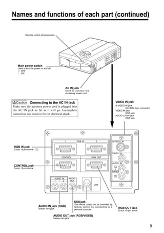
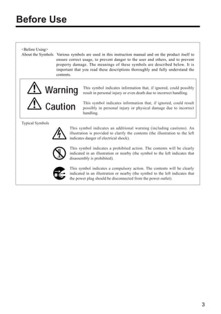
![Names and functions of each part (continued)
Remote control transmitter
VIDEO, RGB button LASER button
Press to switch the input. (Refer to page 13, 19.) VIDEO RGB Turns the laser beam on and off. Refer to page
LASER
11 cocnerning usage and observe the cautions.
STANDBY / ON button STANDBY/ON POSITION
Used to turn the power on and off. POSITION button
Press for 1 sec. or more to turn the power off Pressing the top, bottom, left or right of Disk Pad
(enter standby status). after pressing this button causes corresponding
(Refer to pages13 and 14.) movement (effective only for RGB signal output).
DISK PAD RESET MOUSE / RIGHT button
(1) Used to select menu items when the menu (1)Operates as the RESET button when the menu
screen is displayed (refer to page 16-18). is displayed. Press this button to return to the
(2) When the menu is not displayed, the mouse RESET
initial settings.
shift function and left click function are active. MENU (2)Used to click the right mouse button when the
*1 (3) After the POSITION button has been FREEZE menu is not displayed (refer to page 25,26).
pressed, the screen can be moved upward, *1 (3)Pressing this button after scrolling the screen
downward and to the left and right. MAGNIFY VOLUME with POSITION returns the screen to the original
OFF position.
MENU button
Used to turn the menu screen display on and off.
P in P MUTE FREEZE button
(refer to page 17-21). Used to turn the freeze (still) image display on
BLANK AUTO TIMER
and off.
MAGNIFY button VOLUME button
Used to magnify the displayed image. Adjusts the volume of the sound. Press [ ] to
FOCUS ZOOM
increase the volume and ( ) to decrease the
P in P button *2 volume.
Used to turn P in P (Picture In Picture: displays sub video
signal images in the RGB signal) on and off. MUTE button
Each time this button is pressed, operation will change in Mutes the sound when pressed and restores the
the following sequence: sound when pressed again.
(1) Reduce sub screen (2) Magnify sub screen (3)Off.
(1) ∼ (3) TIMER button
Turns the time display of the timer displayed on
BLANK button the menu screen on and off.
Used to turn blanking on and off. The timer is not displayed during blanking.
(Refer to page 20.) Refer to page 20, 21 concerning the method
used to set the timer.
FOCUS button ZOOM button
Used to adjust the focus of the image on the Used to adjust the size of the image. (Refer to
screen. (Refer to page 13.) page 13.)
AUTO button
Used to execute auto-adjust.*3
*1 POSITION icon *3 Auto adjustment function
When the POSITION button is pressed, the remote control The projector automatically adjusts 4 items (V. POSIT, H. POSIT,
buttons will light and the moving display icon will appear at the H. PHASE, H. SIZE).
bottom right of the screen. When you choose AUTO (move the cursor to the right from the
manual operation position), the AUTO confirmation menu shown
below is indicated.
Caution • Auto adjust requires several tens of seconds.
• Auto adjust may not operate correctly in some cases,
depending on the computer connected and the signal.
• Auto adjust may not operate correctly in some cases,
depending on the type of image.
*2 • Execute auto adjust with the display of the application
With the P in P function, signals are input to both RGB and being run by the computer at maximum.
VIDEO. This function operates only when the RGB signal has • After auto adjust, the image may be slightly dark in
been selected. There is no display in the case of the no signal and some cases due to automatic adjustment of the signal
when the RGB signal is outside the sync range. level.
When P in P is used, audio is automatically switched to video.
In P in P, audio input can be switched by pressing the VOL and • Auto adjust canot execute when the initial display is
VOL keys of the remote control, displaying the audio bar and "NO INPUT IS DETECTED" or "SYNC IS OUT OF
moving Disk Pad left and right during the display. RANGE" during FREEZE or MAGNIFY.
RGB/VIDEO
10](https://image.slidesharecdn.com/hitachiicp-s860elcdprojectormanual-120321115440-phpapp01/85/Hitachii-cp-s860e-lcd-projector-manual-10-320.jpg)
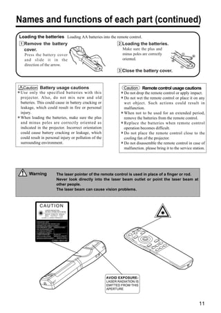
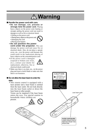
![Basic operations
To project VIDEO
LASER
RGB
2
STANDBY/ON POSITION
7
5 7 4 2 RESET
MENU
FREEZE
MAGNIFY VOLUME
OFF
P in P MUTE
5 BLANK AUTO TIMER
4
1
FOCUS ZOOM
3
1 Turn on the main power switch of the projector [ I: ON].
• The ON indicator will light orange.
2 Press the STANDBY / ON button.
• The ON indicator will blink green and then light green.
• The green blinking indicates warmup.
• After the power is turned on, the lamp will be cooled for approximately 1 min. and the power cannot
be turned on even by pressing the STANDBY/ON button.
3 Remove the lens cap.
4 Use the ZOOM button to adjust the screen size.
5 Use the FOCUS button to adjust the focus.
(1) The display shown to the right will appear when the FOCUS button is pressed. +++FOCUS+++
(2) Use the FOCUS button to adjust the focus until the image is sharp.
(3) The message "Focus" will disappear if any other button is pressed.
6 Turn on the power to the connected equipment.
Refer to page 31 concerning the connection of other equipment.
7 Press either the INPUT button of the
projector or the VIDEO/RGB button of the Example on-screen display
remote control to select the signal to be
RGB 1
projected on the screen.
The selected signal input channel will be displayed in the lower right part of the screen.
13](https://image.slidesharecdn.com/hitachiicp-s860elcdprojectormanual-120321115440-phpapp01/85/Hitachii-cp-s860e-lcd-projector-manual-13-320.jpg)
![Basic operations (continued)
Turning off the power
1
VIDEO RGB
LASER
STANDBY/ON POSITION
1
RESET
MENU
FREEZE
2 MAGNIFY VOLUME
OFF
3 P in P MUTE
BLANK AUTO TIMER
1 Press the STANDBY/ON button for approximately 1 sec.
• The ON indicator will blink orange, then the lamp will turn off. Approximately 1 sec. after that, the
lamp will light orange.
• After the power is turned off, the lamp will be cooled for approximately 1 min. and the power cannot
be turned off even by pressing the STANDBY/ON button.
• The standby status will not be entered if the time which the STANDBY/ON button is pressed is too
short.
2 Turn off the main power switch of the projector [ : OFF].
3 Attach the lens cap.
Caution The fan will continue running for approximately 1 min. after the STANDBY/ON button is pressed.
Do not turn off the main power switch while the lamp is on because this will shorten the service life of
the lamp.
Plug & Play
This projector is VESA DDC 1/2B compatible. Plug & play is possible by connecting to a computer that is
VESA DDC (Display Data Channel) compatible.
(Plug & play is a system configured with peripheral equipment including a computer and display, and an
operating system.
Caution Use the RGB cable included with this projector when using plug & play. With other cables, pins
(12) - (15) are sometimes not connected (effective only for RGB).
14](https://image.slidesharecdn.com/hitachiicp-s860elcdprojectormanual-120321115440-phpapp01/85/Hitachii-cp-s860e-lcd-projector-manual-14-320.jpg)
![Basic operations (continued)
Freeze function
This function is used to freeze the image being displayed. VIDEO
LASER
RGB
This function can be used together with the MAGNIFY function STANDBY/ON POSITION
(refer to page 10).
RESET
MENU
FREEZE
MAGNIFY VOLUME
1 OFF
P in P MUTE
BLANK AUTO TIMER
1 Press the FREEZE button.
• The image being displayed will freeze.
• The [ ] mark will be displayed for approximately 3 sec. when the FREEZE function is on.
Cancelling the FREEZE function
1 Press the FREEZE button.
• The FREEZE function will be cancelled.
• The [ ] mark will be displayed for approximately 3 sec. when the FREEZE function is cancelled.
Caution • Pressing the FREEZE button alternately turns the freeze function on and off.
• The FREEZE function will be cancelled when the input select button is pressed or the display
mode of the PC being used for display is changed.
• The POSITION icon is not displayed while the FREEZE function is being used. The screen cannot
be moved with DISK PAD.
• When a still image signal is input when the FREEZE function is on, make sure not to forget to
cancel the FREEZE function.
• Cancelled when the menu display is turned on during freeze operation.
15](https://image.slidesharecdn.com/hitachiicp-s860elcdprojectormanual-120321115440-phpapp01/85/Hitachii-cp-s860e-lcd-projector-manual-15-320.jpg)
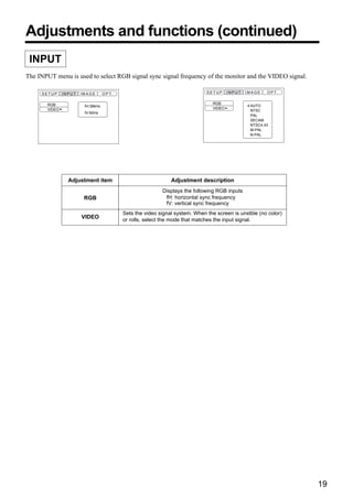
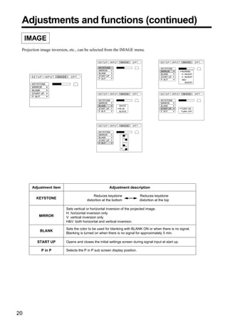
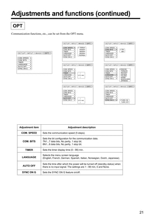
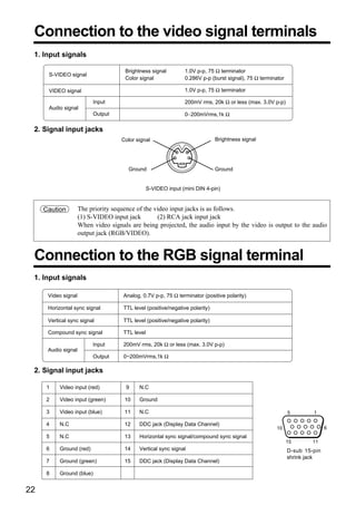
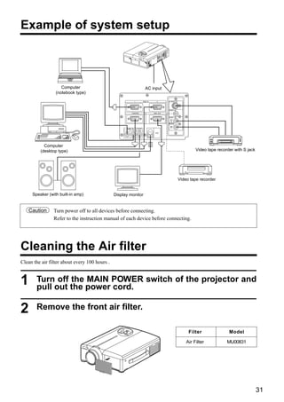
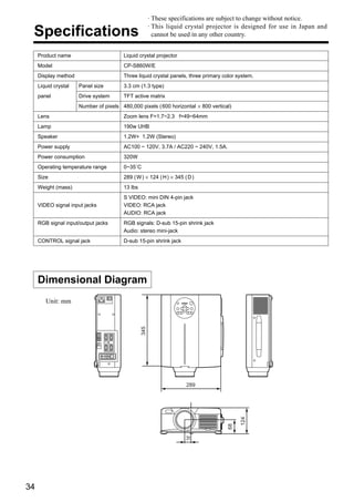


(1) This document is a user's guide for the Hitachi CP-S860W/E liquid crystal projector. (2) The projector uses a UHB lamp and optical system to provide a high level of brightness for projecting computer and video signals onto a screen. (3) Key features include partial image magnification, distortion correction, power zoom/focus, and a P in P function. The guide provides instructions on setup, connections, usage and specifications.


