1. Dr Dilum Fernando,
Moin Rahman, Pranav Rawal, Maddy Courtney, Emma Parisi,
Yiwen Zhu, Chuang Miao, Matt Piesker , Li Min
School of Civil Engineering, The University of Queensland,
Australia
For more information:
www.civil.uq.edu.au/icarus
HFT Thin-Walled Members
INTRODUCTION
The increasing interest in timber as a sustainable construction
material has led to the development of a new type of
structures called “hybrid FRP-timber thin-walled” structures. In
these structures FRP is combined with timber veneers that
makes it light weight, high performing and easy-to-construct. It
harnesses orthotropic properties of both by orienting material
fiber directions for optimal composite properties and efficient
thin-walled cross sectional geometry.
The goal behind this project was to study and develop an
understanding of the behaviour of HFT thin-walled sections that
are ‘rectangular’ and ‘square’ from existing studies done
preliminary on HFT ‘Cee’ sections.
STEEL PLATE & DOVETAIL JOINT
The Steel Plate design consisted of 2mm thick steel plate
(140X300mm) that was attached to the center of the outer web
of the two members via six M8 bolts. Two additional plates
were attached on the inner flanges with 4 M8 bolts Dovetails
were cut into the web of each member using a water jet with
0.4mm diameter. Member 1 had three pins and two tails while
Member 2 had three tails to fit the pins of Member 1 and two
pins to fit the tails of Member 1. The dovetails were reinforced
with a coat of polyurethane and an extra coat of FRP.
BACKGROUND
The project was done in 3 stages – dimensioning & designing,
manufacturing and testing. Firstly, portal frame was selected
as the structure and several design ideas for its
connections/joints were discussed aiming at the central
members of the frame to address only flexural/bending forces
on the members. From multiple designs three joints were
chosen, ‘steel plate’, ‘timber/screw joint’ and ‘dovetail joint’.
Each of these were then fabricated on separate HFT square
or rectangular timber hollow sections. Once that was
completed, the fabricated samples were tested via “4-point
Bending Test” in the UQ Structures Lab.
FINDINGS
Preliminary calculations for each joint hypothesized failure at a
load of less than 1 kN. Each testing was undertaken in a 4-
Point Bending Test on a Tecnotest Testing Machine in the
UQ Structures Labs. Upon testing, Joint 1 withstood a load of
4 kN before failure, Joint 2 withstood 9.6 kN and Joint 3
withstood 7 kN.
Future work with the HFT-Timber composite members includes
the design of joints at perpendicular or otherwise angled
members, and modelling of stress distribution to further
enhance the understanding of HFT Thin-Walled Composite
Members.
TIMBER/SCEW REINFORCED JOINT
The Screw Reinforced Joint design allowed web and flanges
to be reinforced with timber as well as get attached by coats
of polyurethane and FRP. Timber supporting the web was
approximately 10mm thick while the flanges were supported
by 35mm. Initial designs used four 100mm long M12 screws
and bolts supporting the two flanges. However, for testing
purposes, only the outer two screws remained.
Figure 2: Other Steel Plate Joint
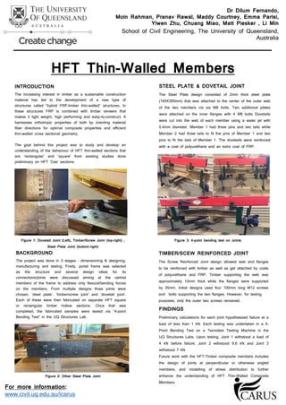
Figure 1: Dovetail Joint (Left), Timber/Screw Joint (top-right) ,
Steel Plate Joint (bottom-right)
Figure 3: 4-point bending test on Joints