Handbook Of Reflector Antennas And Feed Systems Volume 3 Applications Of Reflectors 1st Edition Sudhakar Rao
Handbook Of Reflector Antennas And Feed Systems Volume 3 Applications Of Reflectors 1st Edition Sudhakar Rao
Handbook Of Reflector Antennas And Feed Systems Volume 3 Applications Of Reflectors 1st Edition Sudhakar Rao


![viii Contents
7.2.1 Bends 280
7.2.2 Transitions 281
7.2.3 Filters 282
7.2.4 E-Plane, H-Plane, and Magic Tees 283
7.2.5 Orthomode Transducers 284
7.2.6 Polarizers 287
7.2.7 Horns 289
7.3 Feed Design 289
7.3.1 Integrated Design Approach 290
7.3.2 Other Key RF Design Considerations 290
7.3.3 Precision RF CAD Tools 291
7.3.4 Mechanical and Thermal Design 292
7.3.5 Manufacturing Methods 293
7.4 Feed Examples 295
7.4.1 Standard C-Band Feed 295
7.4.2 Standard Ku-Band Feeds 296
7.4.3 K-Ka-Band Feed 299
7.4.4 Low Profile K-Ka-Band Network for Feed Array 299
7.4.5 K-Ka-Q-Band Network 300
7.4.6 Ku-Band Tracking Feed 301
7.5 Qualification and Protoflight Testing 302
7.6 Feed Assembly Deleterious High-Power RF Effects: Passive
Intermodulation, Gas Ionization/Corona, and Multipactor 304
7.7 Passive Intermodulation 305
7.7.1 The PIM Problem 305
7.7.2 PIM Defined 306
7.7.3 Causes of PIM 307
7.7.4 Mathematical Definition [18, 19] 309
7.7.5 PIM as a Function of Incident Power 311
7.7.6 PIM Mitigation 312
7.7.7 Susceptible Systems 313
7.7.8 Hardware PIM Requirements 313
7.7.9 PIM Test and Verification Methods 314
7.8 Multipactor, Corona, and Ionization Breakdown 320
7.8.1 Multipactor 321
7.8.2 Corona and Ionization Breakdown 324
7.8.3 Hardware Test Requirements 325
Appendix 7A 331
7A.1 Generic PIM Test Setup Equations Related to Far-Field Tx
Flux Density 331
Appendix 7B 332
7B.1 Generic PIM Test Setup Equations Related to Far-Field Rx
Coupling 332
Appendix 7C 333
7C.1 Example Test Procedure 333
References 338](https://image.slidesharecdn.com/2481996-250622031758-a9578963/75/Handbook-Of-Reflector-Antennas-And-Feed-Systems-Volume-3-Applications-Of-Reflectors-1st-Edition-Sudhakar-Rao-13-2048.jpg)


![2 ������������
Introduction
In the 1970s and 1980s, significant developments occurred in both satellite
communication antennas and Earth station antennas. Large Earth stations have
been constructed in the United States, Japan, and Europe that employ shaped dual-
reflector antennas and fixed-feed beam-waveguide technology with a focus on im-
proving the efficiency of antennas. Gridded reflector technology was developed in
Canada and the United States for spacecraft reflector antennas. This technology
allowed for reuse of the aperture space for two orthogonally polarized antenna
surfaces that are placed one behind the other and fed with two separate feed ar-
rays. This in turn allowed for polarization reuse, which enabled the bandwidth to
be increased twofold.
Large-mesh reflector technology was developed in late 1980s and early 1990s
by Harris and Astro-Mesh (now Northrop Grumman) for mobile applications.
This technology allowed for the use of large reflectors (5 to 12m) that could be
folded in a small volume for stowage and deployed in space. More recently, large
reflectors of 22m and more have been built and flown by the space industry for
both commercial and military applications.
During the late 1980s, another important development occurred in the form
of shaped reflector technology [1]. Shaped reflector technology allowed contoured
beam shapes to be created by changing the reflector surface shape and using a sin-
gle-feed instead of large-feed array with a beam-forming network feeding the array.
This technology has significant benefits in terms of reducing the overall mass and
cost of the payloads. Shaped dual-reflector Gregorian systems have been developed
for both linear and circular polarization applications.
Multiple-beam antennas have been developed for mobile and personal commu-
nication applications starting in the 1990s. Several satellite systems, such as M-Sat,
Anik-E, Globalstar, Inmarsat, ACeS, and Thuraya, have employed multiple beams
with frequency reuse schemes to increase the effective bandwidths by factors of 4
to 30. Direct broadcast satellites were developed during the 1990s that resulted in
high-power downlink beams providing regional coverage that allowed users to re-
ceive signals directly from a satellite using pizza-sized dishes at their homes. Local-
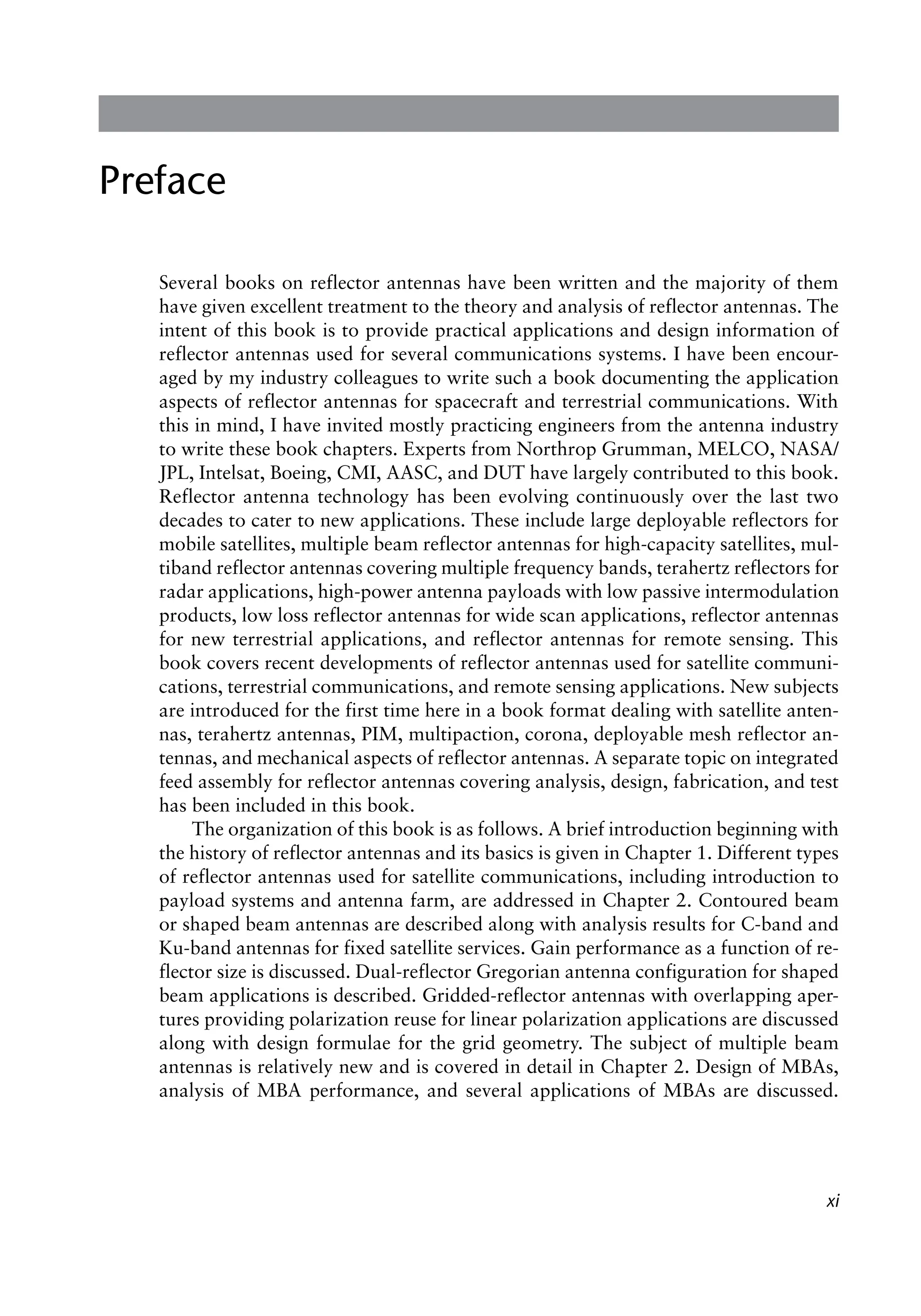
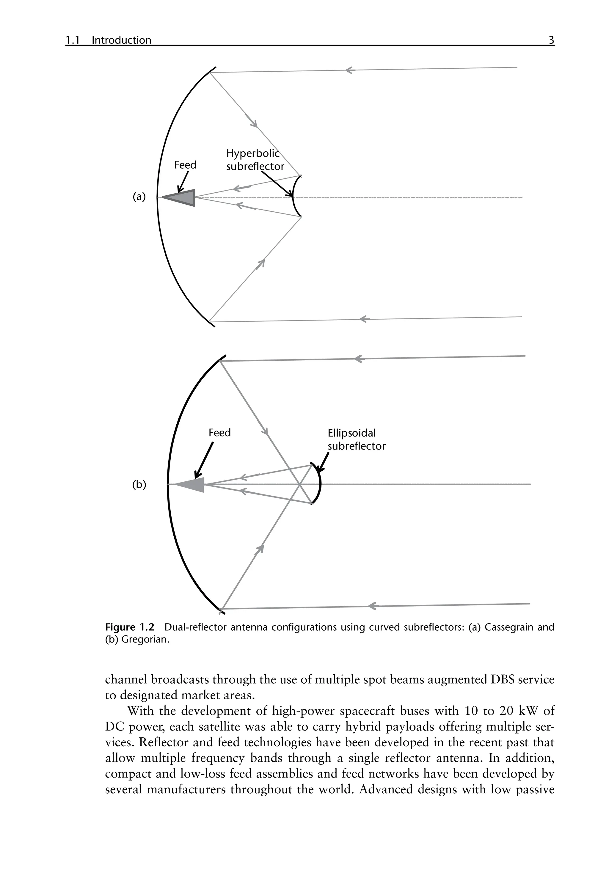
Figure 1.1 Newtonian reflector telescope with planar subreflector.](https://image.slidesharecdn.com/2481996-250622031758-a9578963/75/Handbook-Of-Reflector-Antennas-And-Feed-Systems-Volume-3-Applications-Of-Reflectors-1st-Edition-Sudhakar-Rao-21-2048.jpg)
![4 ������������
Introduction
intermodulation (PIM) products and high-power handling technologies have been
developed during the past 30 years, thus improving the reliability and extending
the capability of the high-power payloads. Reconfigurable reflector antenna tech-
nology has been developed for DABS (digital audio broadcast satellites) and has
been successfully flown on Sirius-1 and Sirius-2 satellites that operate in highly
inclined elliptical orbits. Flat reflector technologies have been developed for radar
and remote sensing technologies.
Several excellent books have covered conventional reflector antennas in the
past [2–6]. However, developments during the past two decades have not been
documented properly. The intent of this volume of the handbook is to address the
latest developments in reflector antennas for space, ground, remote sensing, and
terahertz applications. This volume will be useful for practicing engineers as well as
academic researchers. All of the chapters have been written by experts in the indus-
try and in academia who bring their valuable experience in dealing with practical
antennas, hardware design, and related issues. Some of the topics addressed are
new and documented here for the first time in textbook form.
The key developments in reflector antennas that have occurred during the past
few decades are addressed in this book and include the following topics:
•
• Contoured or shaped beam antennas;
•
• Multiple beam antennas;
•
• Multiband antennas;
•
• Feed assemblies for reflector antennas: design, fabrication, and test;
•
• Passive intermodulation products;
•
• Multipaction and corona;
•
• Reconfigurable antennas;
•
• Reflector antennas for terahertz applications;
•
• Large deployable mesh reflector antennas;
•
• Remote sensing antennas;
•
• Large reflector antennas for Earth stations and gateway applications on the
ground;
•
• Beam-waveguide dual-reflector antennas.
1.2 Reflector Antenna Basics
Reflector antennas are used for transmission and reception of RF signals provid-
ing high gain. They are preferred over other directive antenna types such as array
antennas and lens antennas due to their low cost and low mass and because they
do not require active components, they avoid the use of complex beam-forming
networks, and they provide large bandwidths. Gain and directivity definitions of
reflector antennas are sometimes not correctly used. The directivity of the reflector
antenna is defined as:](https://image.slidesharecdn.com/2481996-250622031758-a9578963/75/Handbook-Of-Reflector-Antennas-And-Feed-Systems-Volume-3-Applications-Of-Reflectors-1st-Edition-Sudhakar-Rao-23-2048.jpg)
![1.2 Reflector Antenna Basics 5
( )
( )
( )
p p
p q f
q f
q f q q f
=
∫ ∫
2
0 0
0 0 2 2
0
0 0
4 ,
,
,
E
D
E sin d d (1.1)
The denominator in (1.1) is the total radiated power and ( )
q f
2
0 0
,
E is the
power radiated per unit solid angle in the angular direction (q0, f0). Directivity can
be obtained by integrating the ideal computed copolar and cross-polar patterns of
the reflector antennas. However, gain of the reflector antenna, G(q0, f0), is lower
than the directivity and includes feed system and reflector losses. It is given as:
( ) ( )
q f q f
= - -
0 0 0 0
, D , L L
G F R (1.2)
The feed loss FL includes insertion loss due to all components of the feed assem-
bly (horn, polarizer, orthomode transducers, filters/diplexers, waveguide bends),
mismatch losses, and thermal losses as applicable. The reflector loss includes con-
ductive loss, loss due to surface errors, and thermal loss (if applicable) and is given
by:
= + +
L C S T
R R R R (1.3)
Conductive loss depends on the material properties of the reflector (graphite,
aluminum, etc.) and the surface loss in decibels can be calculated using Ruze’s for-
mulation [7] as:
( )
pδ l
-
=
2
4 /
10
10log
S
R e (1.4)
The thermal loss is accounted for by computing the directivity with reflector
surfaces at various temperatures and subtracting the directivity value with ambi-
ent surface. This is typically computed since gain measurements with thermal loss
are not feasible in practice. Thermal losses include mispointing losses and surface
distortion losses.
It is important to optimize the directivity of the reflector antenna by design
and minimize the feed and reflector losses through hardware design, manufacture,
and implementation. The key system parameters impacted by the reflector antenna
design are the effective isotropic radiated power (EIRP) and the gain-to-noise tem-
perature ratio (G/T) and are given as:
( ) ( )
= + -
10
10log i r
EIRP dBW P G L (1.5)
where Pi is the input power in watts, G is the antenna gain including losses, and Lr
is the losses between the amplifier and the antenna interface point.
=
Receive antenna gain
G T
System noise temperature
(1.6)](https://image.slidesharecdn.com/2481996-250622031758-a9578963/75/Handbook-Of-Reflector-Antennas-And-Feed-Systems-Volume-3-Applications-Of-Reflectors-1st-Edition-Sudhakar-Rao-24-2048.jpg)
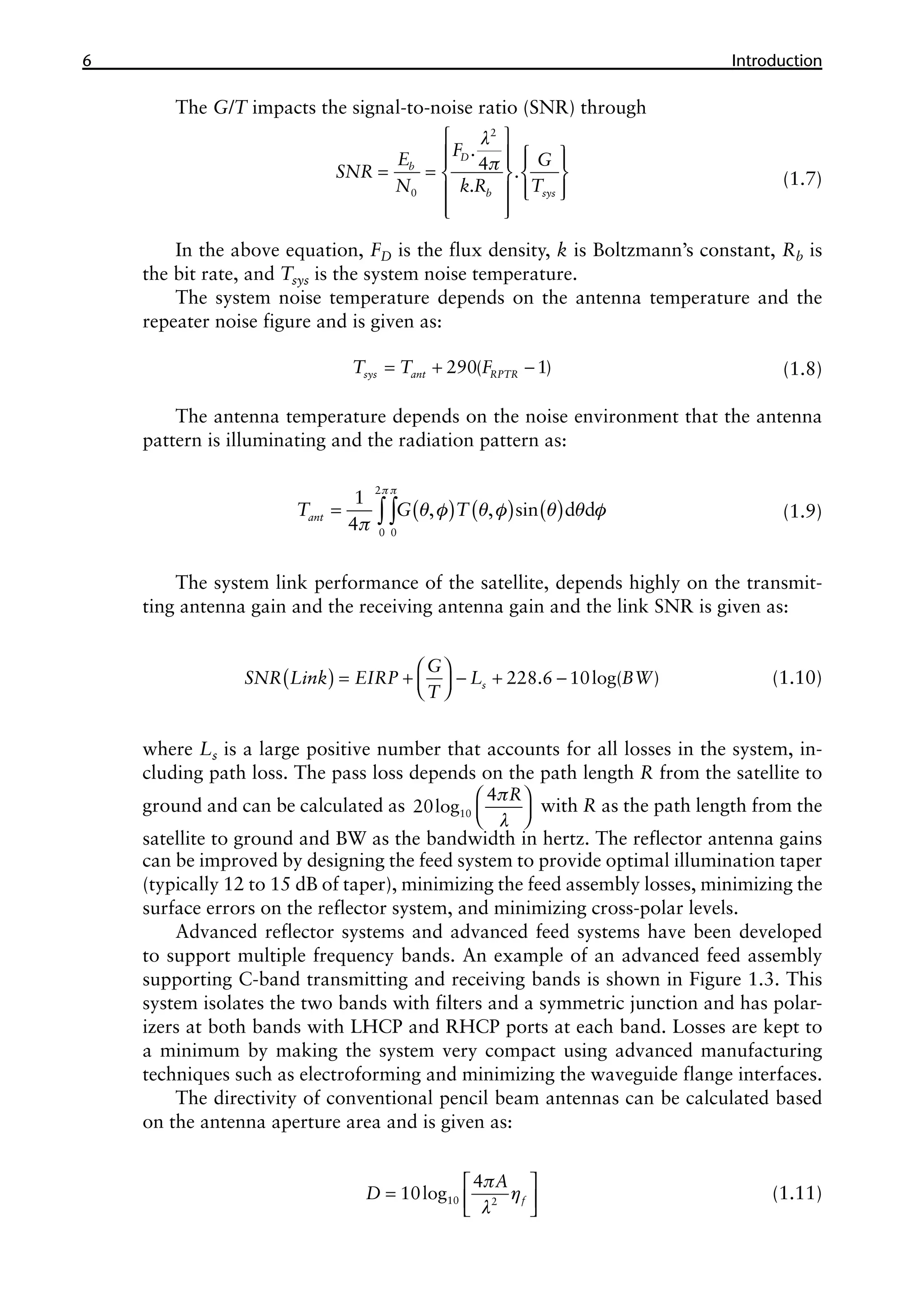
![1.3 Organization of Book Chapters 7
where A is the aperture area, l is the wavelength, and ηf is the overall antenna ef-
ficiency and is given by [8, 9]
( )
q q
η
+
= -
2
2 1 1
2
1
4 cot 1 cos
2 2
n
f
n
n
(1.12)
Equation (1.12) includes spillover efficiency, aperture efficiency, phase effi-
ciency, and polarization efficiency, and can easily be factored into these four subef-
ficiencies. The feed pattern is assumed to be of the form cos
2
n q
in (1.12). The
variable n is related to the feed illumination taper T and is given by
q
-
=
1
10
0.05
cos
2
log
T
n
(1.13)
The maximum value of feed efficiency ηf is about 0.81 and occurs when the
feed illumination taper T is about 10 to 12 dB. In (1.13), θ1 is the half-subtended
angle from the focus to the reflector edges.
1.3 Organization of Book Chapters
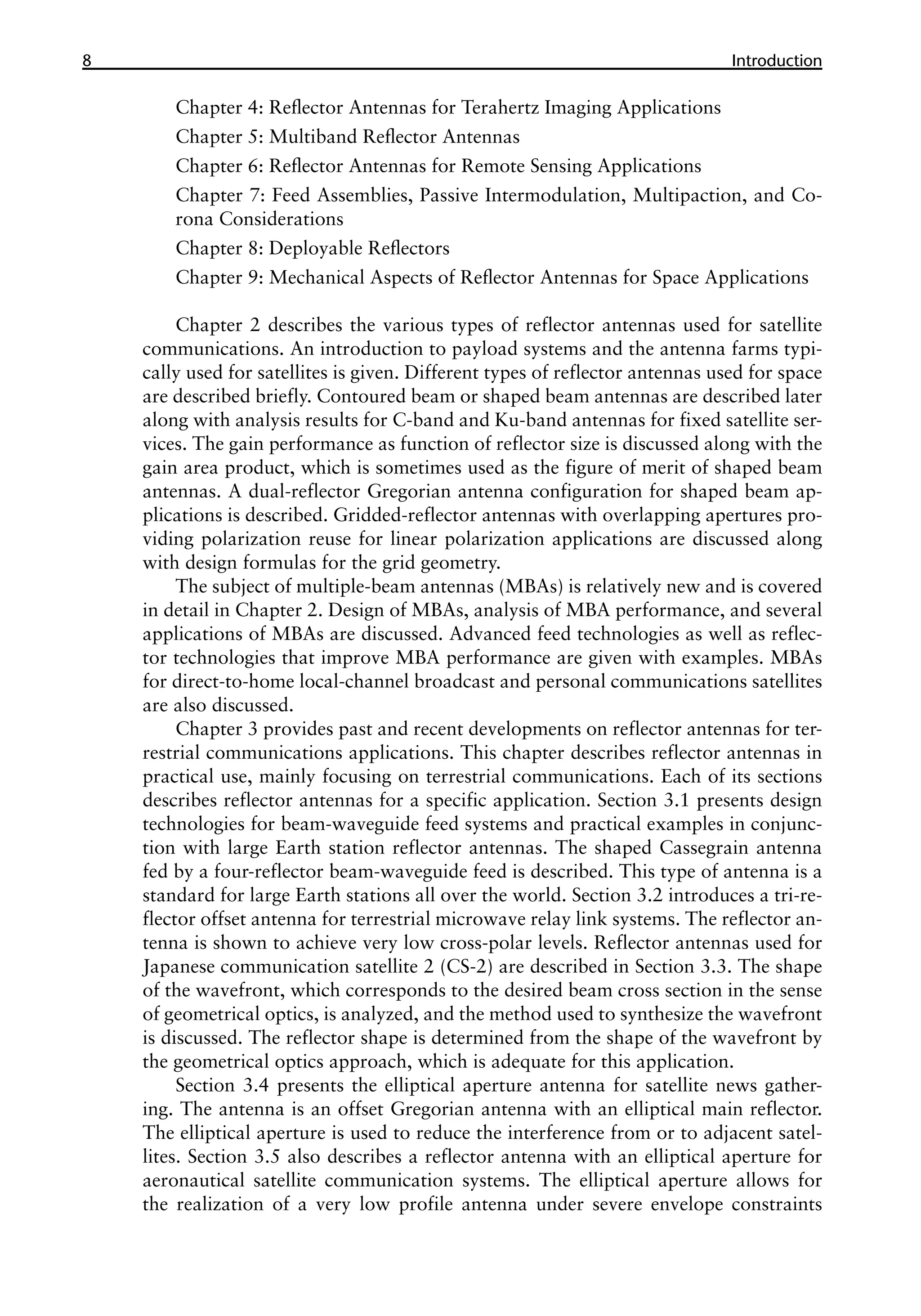
This volume has been organized into the following nine individual chapters:
Chapter 1: Introduction
Chapter 2: Reflector Antennas for Space Communications
Chapter 3: Reflector Antennas for Terrestrial Communications
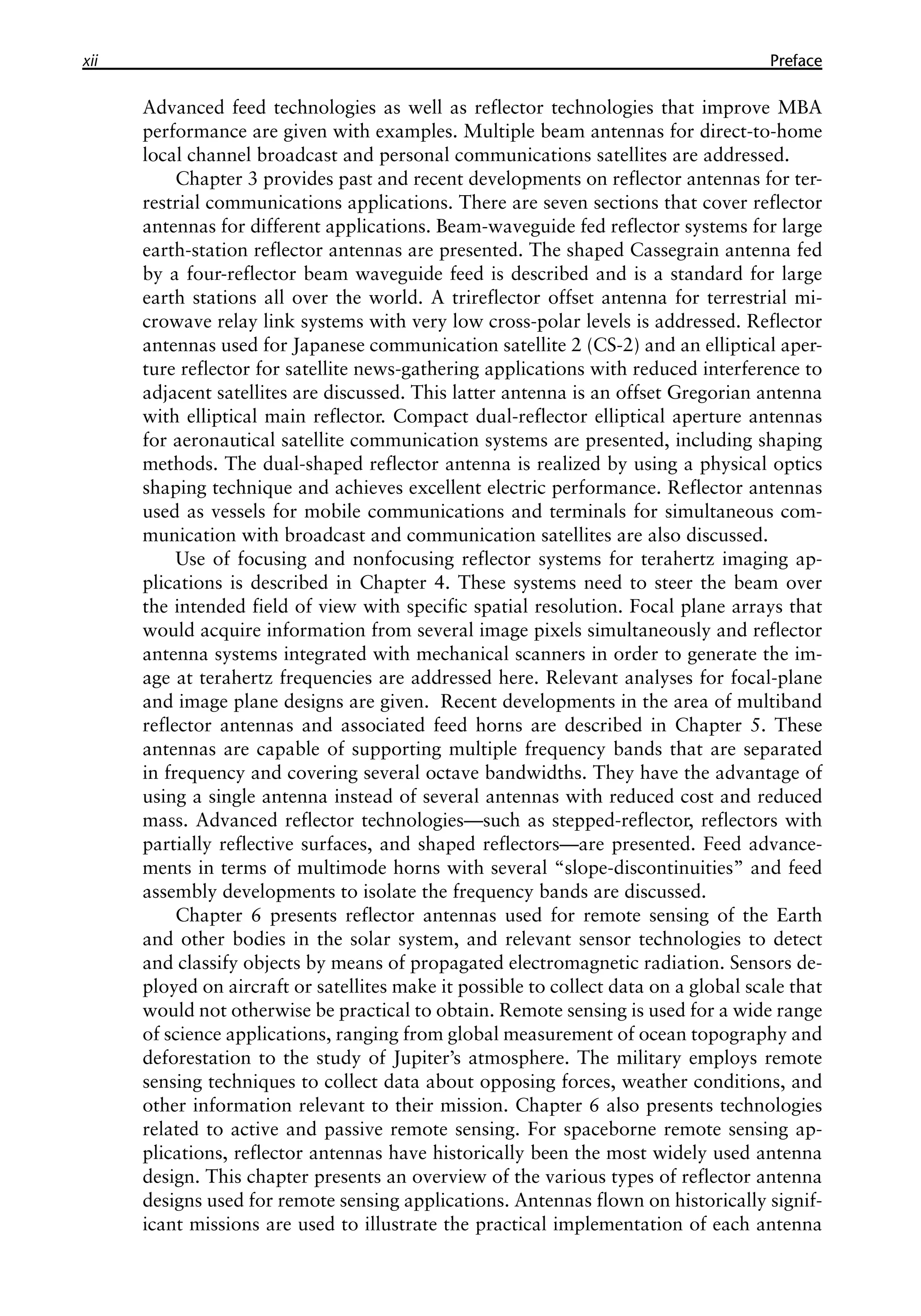
Figure 1.3 A C-band feed assembly with corrugated horn providing dual circular polarization at
both the 4- and 6-GHz bands for fixed satellite services. (Courtesy of Custom Microwave Inc.)](https://image.slidesharecdn.com/2481996-250622031758-a9578963/75/Handbook-Of-Reflector-Antennas-And-Feed-Systems-Volume-3-Applications-Of-Reflectors-1st-Edition-Sudhakar-Rao-26-2048.jpg)
![1.3 Organization of Book Chapters 11
chapter is purposely written to provide general recommendations for configura-
tion, design approach, materials, and testing. A wealth of information is available
from composite materials suppliers, technical papers, and organizations, so it is left
to the reader to perform the detailed analyses, engineering, and materials research
to establish the best possible specific choices relative to the set of requirements for
the particular reflector being considered.
A successful antenna reflector design is always a carefully balanced combina-
tion of many specific and interdependent choices that must all work together to
achieve the best possible results. The mechanical design of reflector antennas has to
satisfy electrical, spacecraft, launch load, vibration, extreme thermal, deployment
in space, stowage, low mass, pointing, and structural requirements simultaneously.
This volume provides all aspects of reflector antennas for space and ground
applications. As the antenna technology moves towards the terahertz regime, new
types of reflector antenna designs and novel manufacturing methods will evolve in
the future.
References
[1] B. S. Westcott, Shaped Reflector Antenna Design, Research Studies Press, UK, 1983.
[2] R. C. Johnson and H. Jasik, Antenna Engineering Handbook, McGraw-Hill, New York,
1984.
[3] W. V. T. Rusch and P. D. Potter, Analysis of Reflector Antennas, Academic Press, San Diego,
1970.
[4] A. W. Rudge et al., The Handbook of Antenna Design, Peter Peregrinus, London, 1982.
[5] P. J. Wood, Reflector Antenna Analysis and Design, Peter Peregrinus, London, 1980.
[6] A. W. Love, “Some highlights in reflector antenna development,” Radio Science, Vol. 11,
pp. 671–684, 1976.
[7] J. Ruze, “Antenna tolerance theory—a review,” Proc. IEEE, Vol. 54, pp. 633–640, 1966.
[8] P. S. Kildal, “Factorization of the feed efficiency of paraboloids and Cassegrain antennas,”
IEEE Trans. Antennas & Propagation, Vol. 33, pp. 903–908, August 1995.
[9] S. Rao and P. S. Kildal, “A study of the diffraction and blockage effects on the efficiency of
the Cassegrain antenna,” Canadian Elec. Eng. Journal, Vol. 9, pp. 10–15, January 1984.](https://image.slidesharecdn.com/2481996-250622031758-a9578963/75/Handbook-Of-Reflector-Antennas-And-Feed-Systems-Volume-3-Applications-Of-Reflectors-1st-Edition-Sudhakar-Rao-30-2048.jpg)

![13
C H A P T E R 2
Reflector Antennas for Space
Communications
Sudhakar Rao, Northrop Grumman Aerospace Systems
C. Babu Ravipati, Intelsat Corporation1
2.1 Introduction
Reflector antennas are widely used in space applications for communication satel-
lites, military satellites, deep space exploration missions, cross-link communica-
tion among satellites, space stations, and remote sensing satellites [1, 2]. The main
reasons for the use of reflector antennas as opposed to other types, such as array
antennas and lens antennas, are mature technology, low cost, high performance,
low losses, low cross-polar levels, light weight, thermal stability, simpler feeds, and
wide bandwidths. A good review of conventional reflector antennas has been pro-
vided by Rudge [3] and Johnson and Jasik [4]. Although parabolic reflectors were
widely used in earlier applications, the design and implementation of advanced
reflector antennas has evolved mostly due to the stringent performance require-
ments and additional capabilities dictated by the space industry operators. Com-
munication satellites have multiple reflector antennas on each spacecraft that cater
to various services. Typical satellite services that employ reflector antennas include
the following:
•
• Fixed satellite services (FSS) that provide shaped or contoured beams for
domestic or regional satellite services. These antennas operate in the C-band,
Ku-band, or Ka-band providing both uplink (satellite receives from ground)
and downlink (satellite transmits to ground) beams from the same antenna
or using two antennas.
•
• Broadcast satellite services (BSS) that provide mostly downlink beams over a
coverage region such as the continental United States. This type of antenna
1. This work does not reflect the views of the authors’ companies (i.e., Northrop Grumman and Intelsat),
which assume no responsibility for the material presented.](https://image.slidesharecdn.com/2481996-250622031758-a9578963/75/Handbook-Of-Reflector-Antennas-And-Feed-Systems-Volume-3-Applications-Of-Reflectors-1st-Edition-Sudhakar-Rao-32-2048.jpg)
![2.1 Introduction 15
some cases on the nadir deck as well. Fixed smaller reflectors without deployment
are placed on the nadir deck of the spacecraft along with tracking, telemetry, and
command antennas and global horns. The majority of the reflectors employ an off-
set configuration to avoid blockage by the feed(s) and/or subreflectors. The feeds
for all of the reflectors are fixed on the east-west corners of the spacecraft and on
the nadir deck. This is due to the fact that the feed assemblies carry high power and
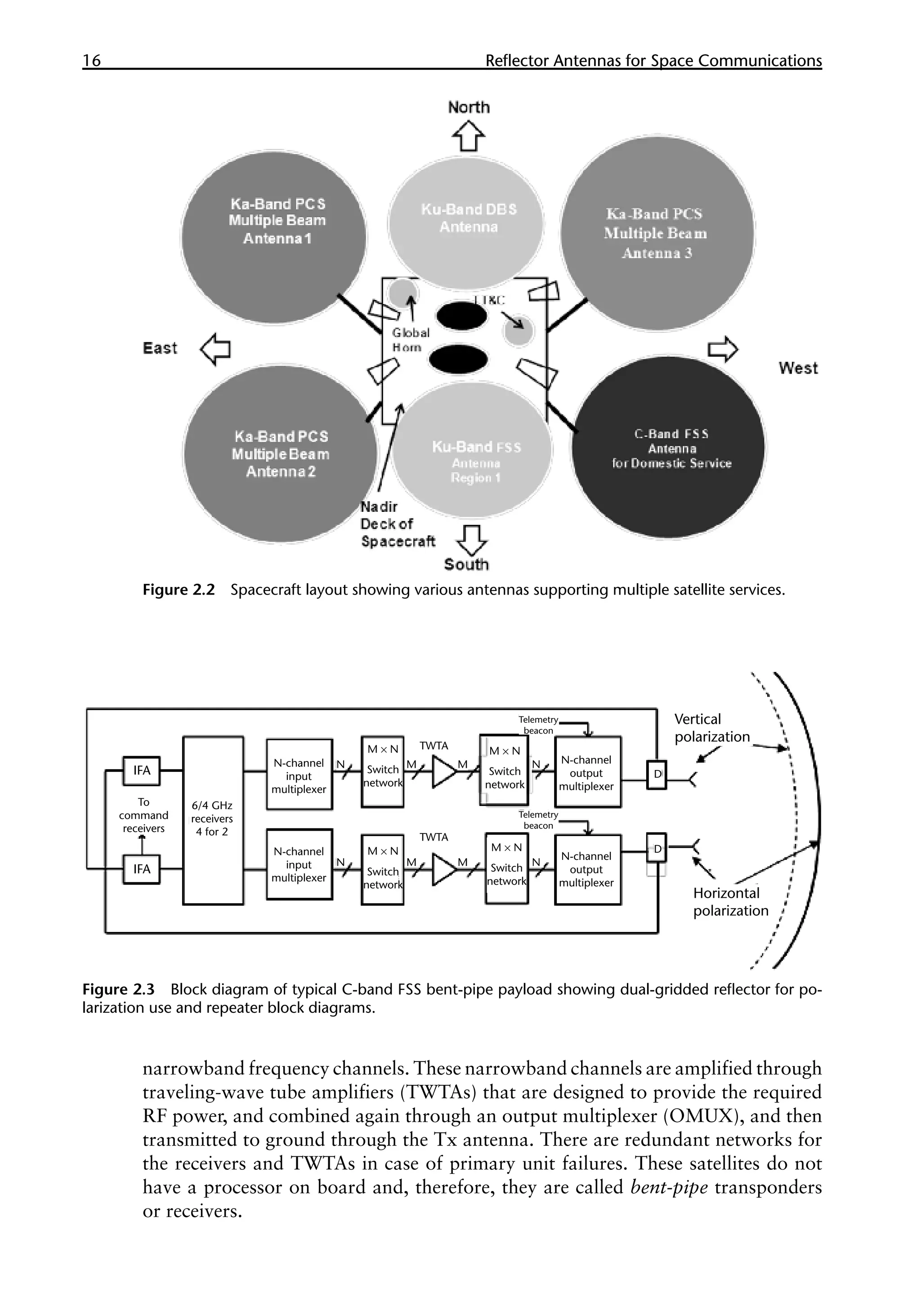
are sensitive to passive intermodulation (PIM). Figure 2.2 shows a typical satellite
in the deployed configuration. Solar panels are deployed along the north-south
directions to track the sun.
The payload for any satellite service includes the antenna subsystem and the
repeater subsystem. The antenna provides the desired radiation characteristics in
terms of beam shape tailored to the coverage region, required gain to close the
communication links, desired polarization (either single or dual), diplexing func-
tion between the Tx and Rx bands, high cross-polar isolation for polarization reuse
systems, copolar isolation outside the coverage, and sidelobe shaping as desired by
the customer needs.
Figure 2.3 shows the block diagram for a bent-pipe satellite payload providing
FSS service. The reflector antenna in this example employs a gridded reflector with
two overlapping surfaces where the front reflector provides vertical polarization
and the back surface provides horizontal polarization. Each reflector is shaped to
provide a contoured beam over the coverage region and is fed with its own horn
with either vertical or horizontal polarization. Each feed is diplexed to isolate the
Tx and the Rx frequency bands. On the receiving side, the antenna receives the
RF signals from ground. The uplink signals go through the input filter assembly
(IFA), receivers that downconvert the 6-GHz signals to 4-GHz signals, and then
through input multiplexers (IMUX) that separate the wideband signal into various
Figure 2.1 Illustration of the various communication links for satellite communications. (© 1985
IEEE. From [13].)
Direct broadcast satellite
Uplink
Downlink
TT&C
link
Communication link
(uplink and downlink)
Domestic satellite (FSS)](https://image.slidesharecdn.com/2481996-250622031758-a9578963/75/Handbook-Of-Reflector-Antennas-And-Feed-Systems-Volume-3-Applications-Of-Reflectors-1st-Edition-Sudhakar-Rao-34-2048.jpg)

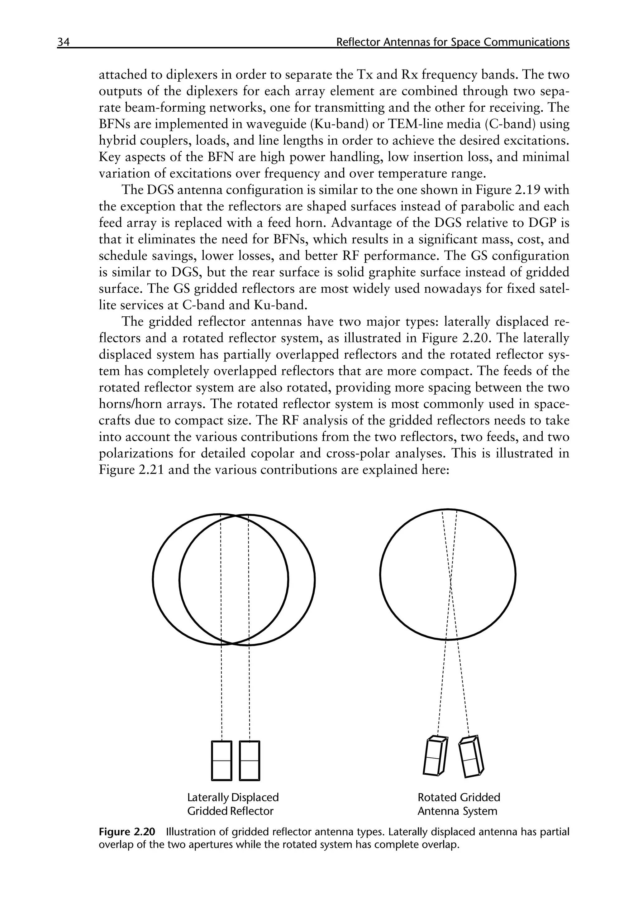
![18 �������������������������������������������
Reflector Antennas for Space Communications
•
• Single-offset reflector (shaped or unshaped).
•
• Dual-reflector Gregorian in both offset and symmetric configurations
(shaped or unshaped).
•
• Gridded reflector for linear polarization reuse (typically shaped surfaces).
•
• Center-fed Cassegrain reflector for intersatellite links and offset-fed Casseg-
rain reflector.
•
• Large deployable mesh reflectors for mobile services.
•
• Single reflector imaging antennas.
•
• Dual-reflector antennas for large scan applications [side-fed offset Casseg-
rain (SFOC) and front-fed offset cassegrain (FFOC) antennas].
•
• Confocal reflector antenna.
Some of these reflector antennas are discussed in this chapter; others are presented
in other chapters of this three-volume handbook.
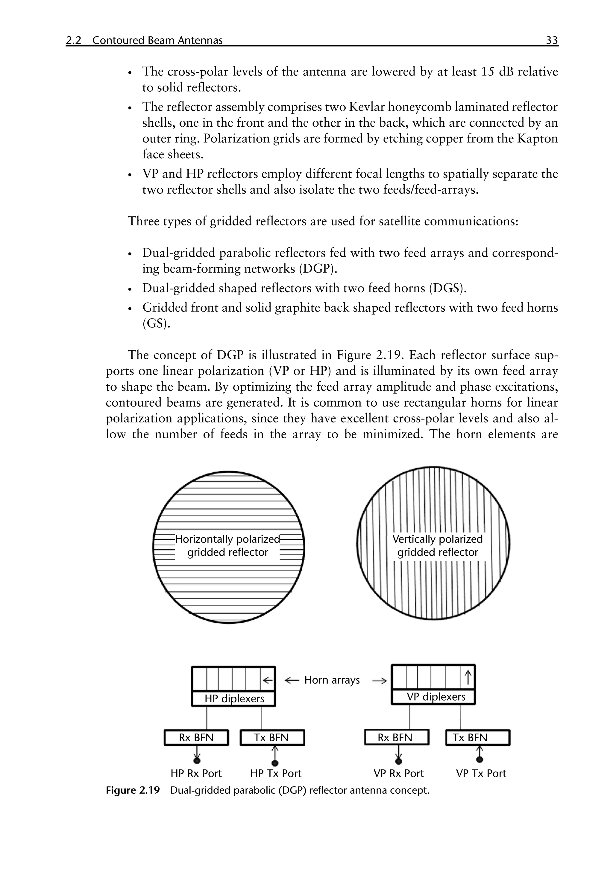
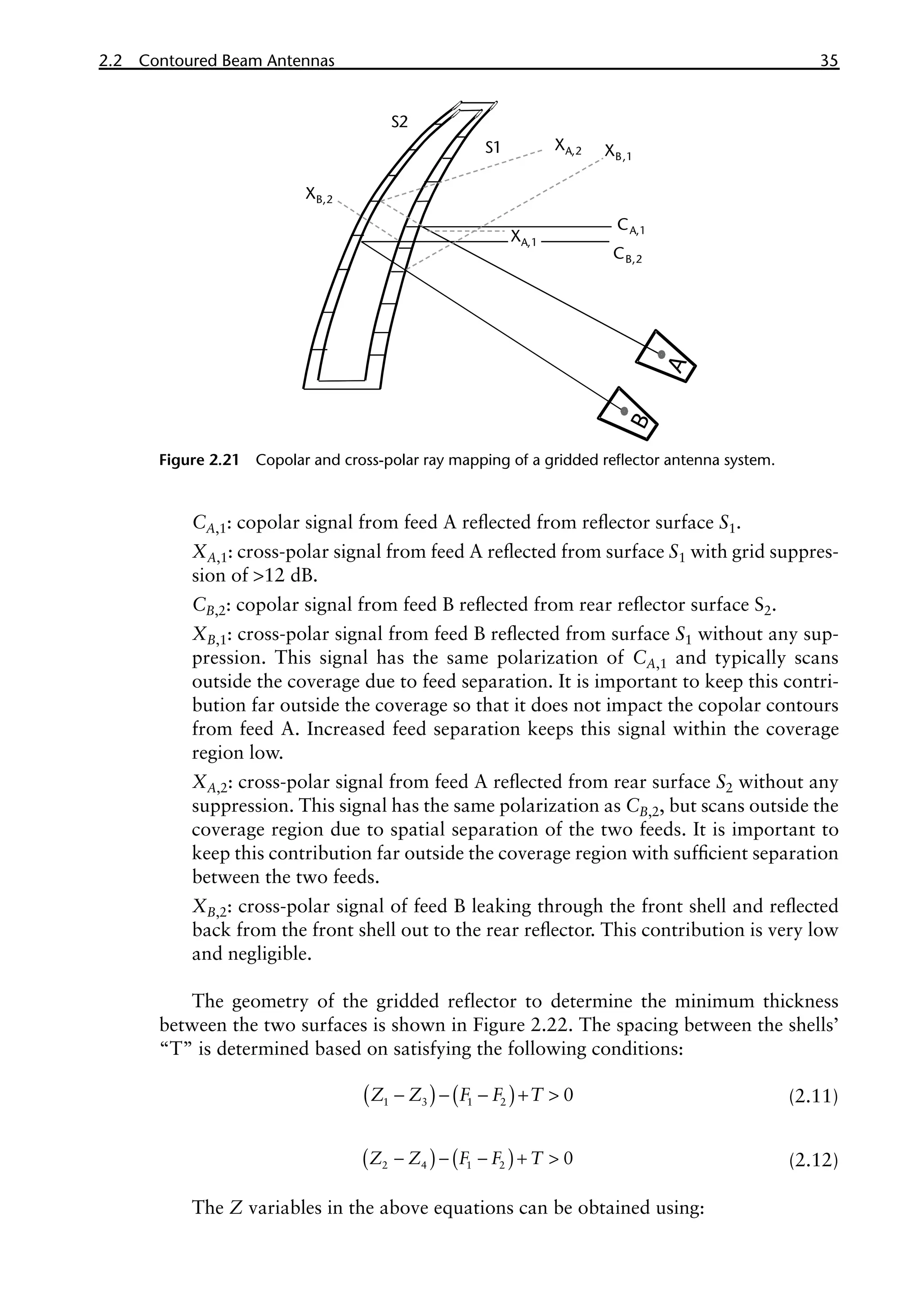
2.2 Contoured Beam Antennas
The contoured beam antennas are the most widely used type in satellite communi-
cations. They are also called shaped beam antennas. These antennas provide down-
link and/or uplink beams that are tailored to fit the geographic coverage region as
seen from a geostationary satellite from a given orbital slot. Contoured beams can
be generated using phased arrays or reflectors. Phased arrays have these limita-
tions: narrow bandwidth, lower efficiency of SSPAs, higher DC power dissipation,
increased delivery schedule, and increased cost and mass. Reflector antennas are
most commonly used for contoured beam applications and other satellite applica-
tions. Offset-fed reflector configurations (single or dual) are suitable for eliminating
the geometrical blockage caused by feeds/subreflectors and are simpler to accom-
modate on spacecraft. Two methods are used to generate a contoured beam on the
ground from a satellite using reflector antennas: (1) a parabolic reflector that is fed
with a feed array and (2) a shaped reflector with a single feed.
Satellite payloads prior to 1990 employed parabolic reflectors with a large
number of feed horns [5, 6]. The RF signals to the feed array are combined through
a beam-forming network (BFN) with appropriate amplitude and phase weight-
ings that are designed to shape the beam. The BFN is realized using a waveguide
medium at the Ku-band and higher bands and using a TEM-line medium (also
referred as square-ax medium) at the C-band and lower bands to reduce mass. It
is designed using a number of couplers with different coupling values, line lengths
for phase optimization, phase-slope equalizers for maintaining the phase distribu-
tion over the frequency band, and filters to reject frequencies outside the band.
Because of the bandwidth limitation of the BFN, the parabolic reflector with feed
array requires two such antennas: one for transmitting and another for receiving,
which makes it expensive and heavy. The shaped reflector with a single feed avoids
the need for a BFN and typically requires a single wideband antenna supporting
both Tx and Rx beams. The Tx and the Rx frequency bands are separated through](https://image.slidesharecdn.com/2481996-250622031758-a9578963/75/Handbook-Of-Reflector-Antennas-And-Feed-Systems-Volume-3-Applications-Of-Reflectors-1st-Edition-Sudhakar-Rao-37-2048.jpg)
![2.2 Contoured Beam Antennas 19
a diplexer. The two methods of generating the contoured beams are illustrated in
Figure 2.4.
2.2.1 Single-Offset Shaped Reflector Antenna for Contoured Beams
This section describes the single-offset solid reflector used for contoured beam
applications. The reflectors are typically made of graphite material for thermal
stability and lower mass. The primary objective of the design is to maximize the
Figure 2.4 (a) Schematic of parabolic reflector with multiple feeds and BFN for contoured beam
applications. The Rx antenna is similar to the Tx antenna except for the frequency difference. (b)
Schematic of shaped reflector antenna with single feed for contoured beam applications. OMT =
ortho-mode transducer, DIPL = diplexer, Tx = transmitting function, Rx = receiving function, VP =
vertical polarization, HP = horizontal polarization. (© 1999 IEEE. From [18].)
F F F
Transmit BFN
Receive reject filters
Offset parabolic reflector
(a)
(b)
OMT
DIPL DIPL
Tx
VP
Tx
HP
R x
VP
R x
HP
Shaped Reflector](https://image.slidesharecdn.com/2481996-250622031758-a9578963/75/Handbook-Of-Reflector-Antennas-And-Feed-Systems-Volume-3-Applications-Of-Reflectors-1st-Edition-Sudhakar-Rao-38-2048.jpg)

![2.2 Contoured Beam Antennas 21
q q q
= +
*
1 0 (2.6)
The angle θ0 determines the feed illumination taper on the reflector and is designed
with a minimum taper of 15 dB at the lowest frequency of the band(s). It is impor-
tant when selecting the offset clearance h that consideration be given to maintaining
a blockage-free condition for all coverage angles of the contoured beam from the
antenna boresight. The maximum angle for blockage-free condition θsm depends
on the offset clearance, focal length, and the diameter d of the feed and is given as:
( )
q
q
q
- -
-
= -
-
-
*
1 1
2 2
*
0.5 cos
tan tan
0.5 cos
4 4
sm
h h d
h d
F F
F F
(2.7)
For linear polarization applications, the cross-polar isolation is intrinsically
poor because of the offset configuration of the reflector. Cross-polar suppression
in addition to the copolar gain contours needs to be incorporated as part of the
synthesis for reflector shaping. However, for circular polarization applications, the
reflector does not induce any cross-polar components and the feed assembly cross-
polar levels due to the feed horn and polarizer dominate the antenna level cross-
polar isolation. The offset geometry causes beam squint in the offset plane and is
given approximately as [7, 8]:
l q
q
p
-
=
*
1 sin
sin
4
L
BS
F
(2.8)
The beam squint occurs in the plane of symmetry and the direction depends on
the sense of polarization (LHCP or RHCP). The feed location needs to be displaced
Figure 2.5 Geometrical parameters of the shaped reflector antenna. (© 2003 IEEE. From [19].)
h
D
F
θ₂
θ₁
θ₀
θ *
Non-linear phase distribution
of shaped reflector antenna in
the aperture plane of the reflector](https://image.slidesharecdn.com/2481996-250622031758-a9578963/75/Handbook-Of-Reflector-Antennas-And-Feed-Systems-Volume-3-Applications-Of-Reflectors-1st-Edition-Sudhakar-Rao-40-2048.jpg)
![22 �������������������������������������������
Reflector Antennas for Space Communications
slightly from the reflector focus in order to compensate for the beam squint for
single sense of circular polarization application or can be accounted for in the shap-
ing process.
Reflector synthesis can be carried out by two methods. An indirect method
involves designing the surface of the reflector such that it produces a given aperture
field, which is known to generate a desired far field. The synthesis of the desired
aperture field most often involves the iterative solution of partial differential equa-
tions that describe the relationship between feed and aperture power distributions,
and is based on geometrical optics (GO).
The second method is a direct method and is the method most oftenly used.
In this method, the reflector system is designed such that it produces a prescribed
far field. The reflector is initially defined in terms of a base surface, for example, a
paraboloid, and a perturbed surface is then superimposed on the base surface [9].
The perturbed surface is defined in terms of a series expansion function such as
Zernike polynomials or cubic spline functions. At each iterative stage the far field
is calculated at a number of sample points and compared to the objective func-
tion. This is used to change the coefficients of the expansion until a better match
is achieved. Physical optics is used to obtain the far field in each calculation. Typi-
cally the expansion functions used are cubic splines because they provide the best
fit for rapidly varying surfaces due to their local nature. Zernike polynomials are
also used to define the surface. TICRA’s POS and GRASP commercial software
programs [10] are used as industry standards for synthesis and analysis of shaped
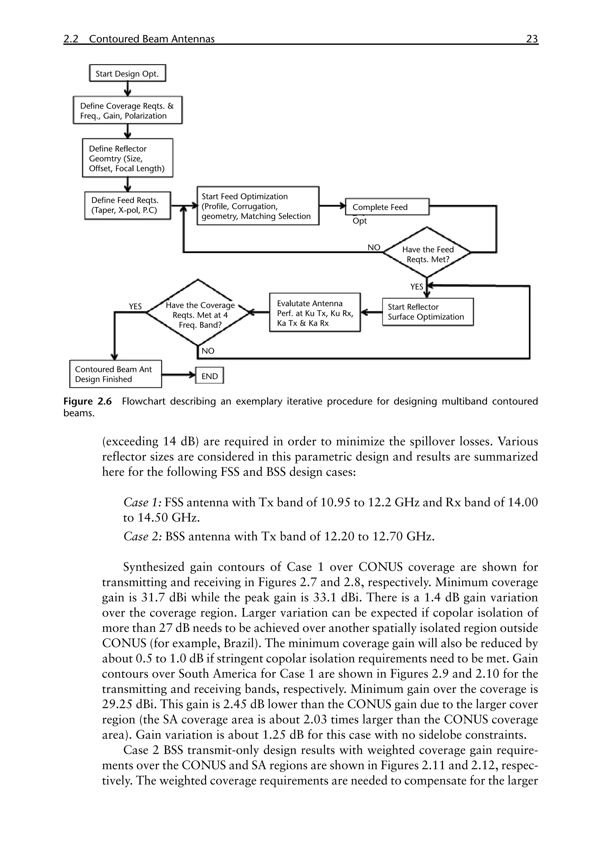
reflector contoured beam antennas. A flowchart for the contoured beam design is
illustrated in Figure 2.6.
The performance of the contoured beam is sometimes defined in terms of gain
area product (GAP). An ideal GAP for a uniformly illuminated coverage area with
no radiation outside the coverage is 41,253 [4p steradians = 4*π*(180/π)*(180/π)].
This is not practical because it requires an infinite size reflector with no spillover
and other losses. The GAP for contour beams is generally in the range of 6,000 to
25,000 and is highly dependent on the reflector size relative to wavelength (D/λ),
bandwidth of operation, the coverage shape, cross-polar isolation, and sidelobe
isolation outside the coverage region. The gain in GAP is the minimum gain over
the coverage region, which usually occurs near the edge of the coverage. The gain
variation over the coverage region designed with uniform weighting depends on
the reflector size and the coverage area and varies in the range of 1.0 to 4.0 dB. A
larger reflector tends to have more uniformly shaped contoured beams with less
gain variation over the coverage region and hence provides better edge-of-coverage
gain.
Ku-Band Contoured Beam Design
Examples of the contoured beam design for Ku-band FSS and BSS payloads are
discussed in this section. Two coverage regions, the continental United States (CO-
NUS) and South America (SA), are considered from a geostationary satellite at a
101° W orbital slot. The coverage areas on ground as seen from a geostationary
satellite are 13 square degrees for CONUS and 26.45 square degrees for SA. The
reflector is illuminated with a corrugated feed having a minimum illumination of
14 dB at Tx frequencies and 19 dB at Rx frequencies. Such high illumination tapers](https://image.slidesharecdn.com/2481996-250622031758-a9578963/75/Handbook-Of-Reflector-Antennas-And-Feed-Systems-Volume-3-Applications-Of-Reflectors-1st-Edition-Sudhakar-Rao-41-2048.jpg)
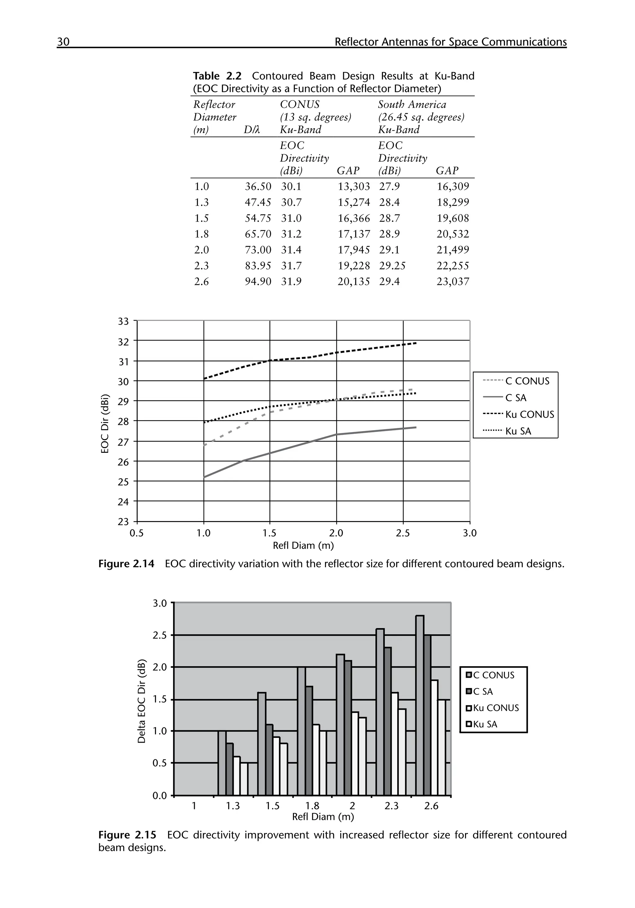
![2.2 Contoured Beam Antennas 27
size is shown. Figure 2.15 shows the EOC gain delta as a function of the reflector
size. The gain values with a 1.0m reflector size are used as a reference in the plot
shown in Figure 2.15.
2.2.2 Dual-Offset Gregorian Reflectors
The dual-reflector shaped Gregorian is widely used for both FSS and BSS applica-
tions. It gives better cross-polar performance relative to a single shaped reflector
for linear polarizations. Also, it has two reflector surfaces that provide better shap-
ing potential of the contoured beams. It is well known that an offset dual-reflector
antenna can be designed to eliminate geometrical optics cross-polarization in the
main reflector aperture [11, 12]. The feed horn is typically larger since it illuminates
the smaller subreflector with an illumination taper of better than 15 dB. The sub-
reflector is generally in the near-field region of the feed horn and near-field analysis
of the feed horn is required through the use of spherical harmonics. Diffraction ef-
fects may increase the cross-polarization in a practical offset dual-reflector system,
especially one with small subreflectors. To avoid this, an enlarged subreflector size
is often used, particularly at C-band frequencies. Typical sizes of Gregorian reflec-
tors are:
•
• Deployable reflectors: 2m and higher main and 0.7m sub (at Ku-band).
•
• Earth deck: 0.8 to 1.5m main and 0.45m sub (Ku-band).
•
• Steerable beam applications: 0.8 to 1.0m main and 0.4m sub.
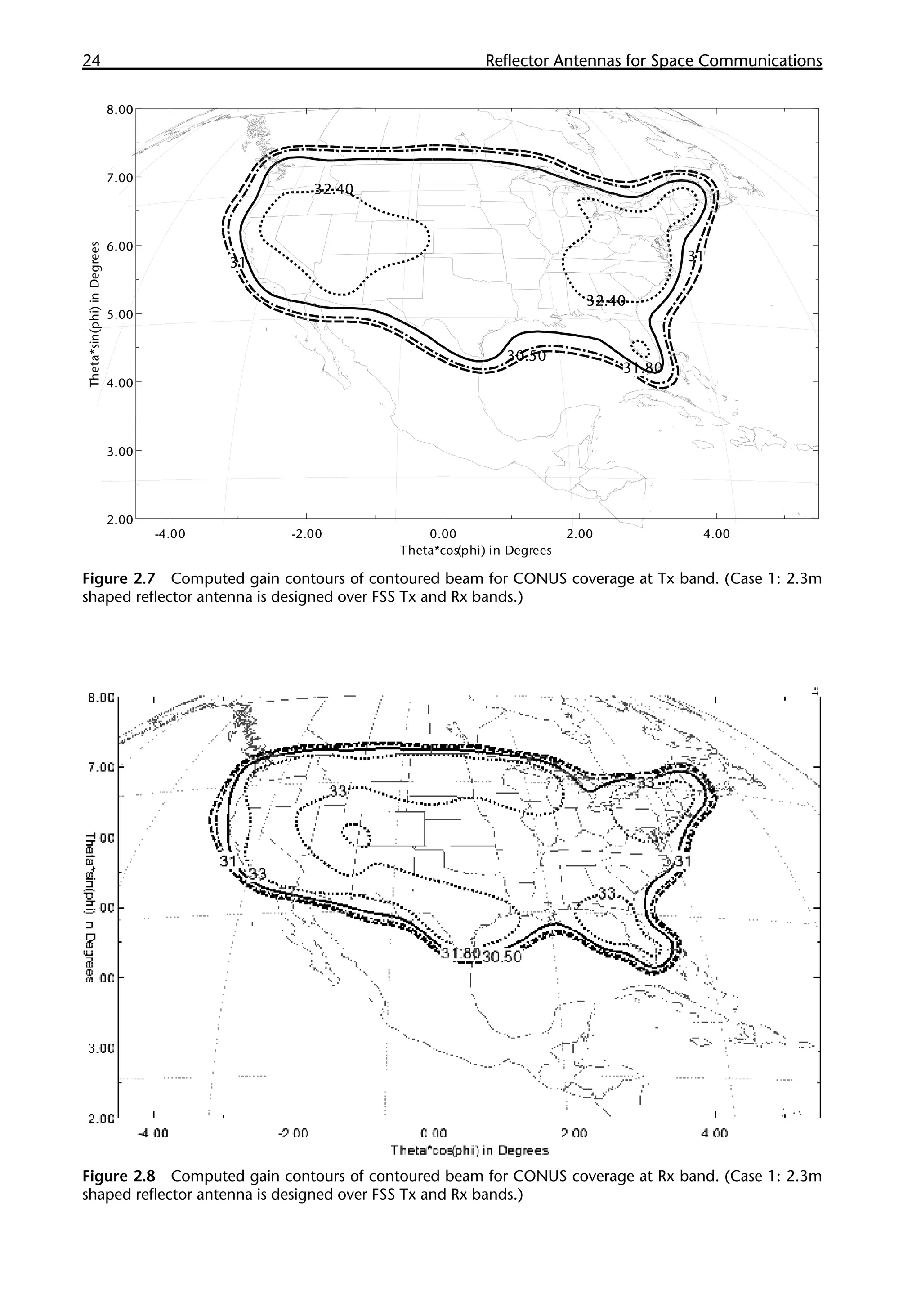
Figure 2.11 Computed gain contours of weighted contoured beam for CONUS coverage at Tx band. (Case
2: 2.3m shaped reflector antenna is designed over BSS Tx bands.)](https://image.slidesharecdn.com/2481996-250622031758-a9578963/75/Handbook-Of-Reflector-Antennas-And-Feed-Systems-Volume-3-Applications-Of-Reflectors-1st-Edition-Sudhakar-Rao-46-2048.jpg)
![28 �������������������������������������������
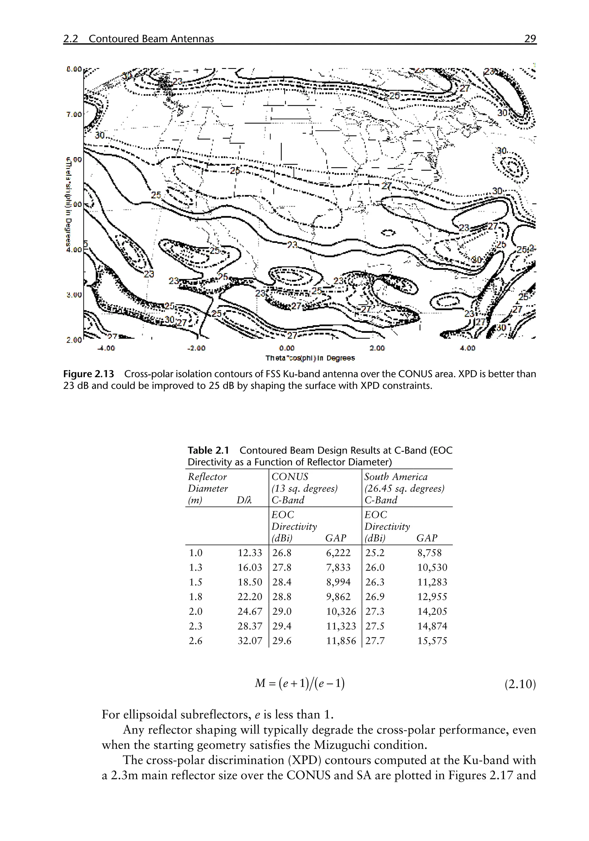
Reflector Antennas for Space Communications
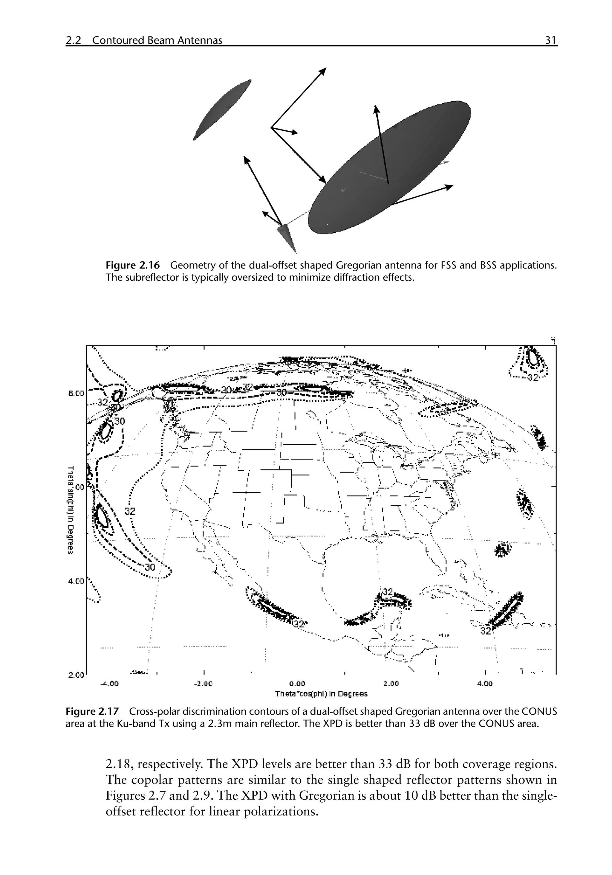
The geometry of the dual-offset Gregorian antenna that satisfies the low cross-
polar Mizuguchi condition [11] is illustrated in Figure 2.16. The geometry of the
system can be specified by the following six parameters:
•
• Diameter of the main reflector, D.
•
• Focal length of the main reflector, F.
•
• Half distance between the focal points of the subreflector, C.
•
• Eccentricity of the sub reflector, e.
•
• Angle between the main reflector and subreflector axis, α.
•
• Angle between the subreflector and feed axis, β.
The Mizuguchi condition, for unshaped reflectors, is given by:
( ) ( )
α β
=
tan 2 tan 2
M (2.9)
where M is the magnification and is related to the eccentricity as follows:
Figure 2.12 Computed gain contours of weighted contoured beam for SA coverage at Tx band.
(Case 2: 2.3m shaped reflector antenna is designed over BSS Tx bands.)](https://image.slidesharecdn.com/2481996-250622031758-a9578963/75/Handbook-Of-Reflector-Antennas-And-Feed-Systems-Volume-3-Applications-Of-Reflectors-1st-Edition-Sudhakar-Rao-47-2048.jpg)


![Reflectarray antenna [Antenna]](https://cdn.slidesharecdn.com/ss_thumbnails/antennafinaal-190716164257-thumbnail.jpg?width=640&height=640&fit=bounds)