This paper presents a compact single-layer microstrip patch antenna designed for WLAN applications, operating within the frequency range of 3.6 to 15 GHz, utilizing coaxial feeding techniques. Simulation results show stable radiation characteristics, with the antenna achieving a bandwidth of 140 MHz at a resonant frequency of approximately 2.34 GHz, suitable for 802.11 WLAN use. The study highlights the advantages of the proposed antenna design, including low cost, compact size, and improved performance for high data rate communications.
![The International Journal Of Engineering And Science (IJES)
|| Volume || 3 || Issue || 8 || Pages || 64-68 || 2014 ||
ISSN (e): 2319 – 1813 ISSN (p): 2319 – 1805
www.theijes.com The IJES Page 64
Multiband Circular Microstrip Patch Antenna for WLAN
Application
1Jaijit Singh , 2 Sonam Thakur, 3Kanchan Sharma,
1Department Of ECE GTBIT (Delhi) ,
2,3Department of ECE, IGDTUW Kashmere Gate, Delhi – 110006
--------------------------------------------------- ABSTRACT-------------------------------------------------------
A compact single layer Microstrip Patch Antenna (MSA) for 3.6 – 15 GHz WLAN applications is presented in
this paper. The implementation of proposed technique is commercially performed using available
electromagnetic simulators. These simulators are mainly based on the method of finite difference time domain
(FDTD) to achieve the desired specifications. The circular patch antenna with optimal co-axial feed is
determined and used for 802.11 WLAN applications. The obtained results show stable radiation characteristics
in the desired band. The experimented results for BER and power radiation are also presented.
Keywords BER ,BW, Co-Axial Feed , CST, Microstrip Patch Antenna (MSA), PEC, WLAN
----------------------------------------------------------------------------------------------------------------------------- ----------
Date of Submission: 10 August 2014 Date of Publication: 30 August 2014
----------------------------------------------------------------------------------------------------------------------------- ----------
I. INTRODUCTION
Due to increasing growth of wireless systems and demand for a variety of new wireless applications
like WLAN, design of broadband and high gain antennas to cover a wide frequency range is highly in demand.
The study of above will be beneficial in applications like high performance aircraft, satellite, missile, mobile
radio and wireless communications. The design and implementation of the above antennas have several
advantages like small size, low-cost fabrication, low profile, conformability, ease of installation and integration
with feed networks.
With advancement of technology, the requirement of an antenna to resonate at more than one frequency i.e.
multi-banding is also increasing day by day. Microstrip patch antenna is best choice to fulfil the above
requirements. Along with that a Microstrip patch antenna offers many advantages like low fabrication cost,
supports both linear as well as circular polarization etc. Bandwidth of a Microstrip patch antenna can be
improved by various methods like cutting U-slot [1], increasing the substrate height, decreasing of substrate
width etc. Antenna array can also be used to improve the bandwidth [2]. In this paper a simple Microstrip patch
antenna with coaxial feed is designed [3],[4].
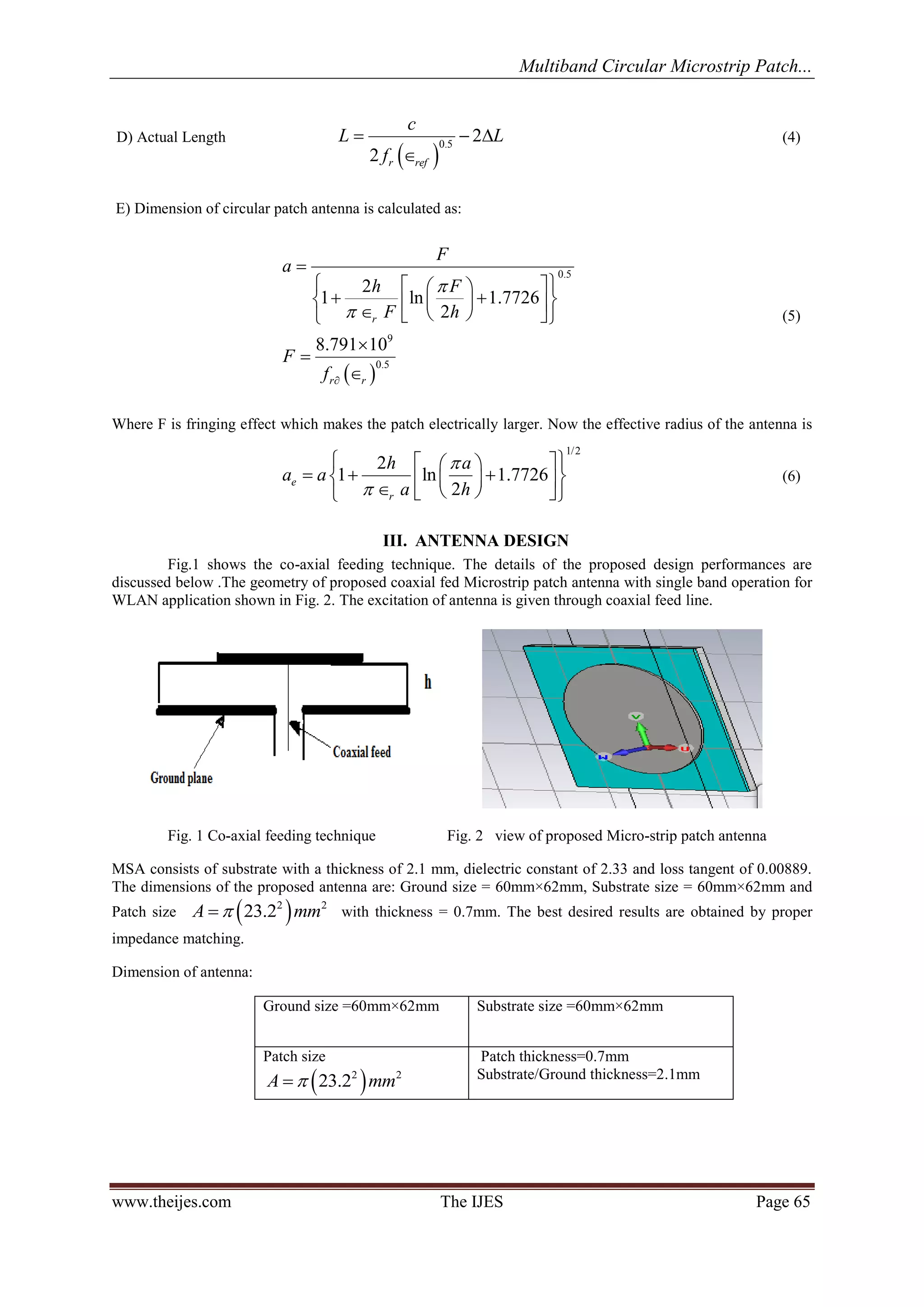
II. ANTENNA DESIGN CALCULATIONS
A) Calculation of width: For efficient radiation, the width w is given as
2
2 1 r r
c
w
f
(1)
B) Calculation of Extension length:
0.412 ( 0.3) 0.264
0.258 0.8
ref
ref
w
h
h
L
w
h
(2)
C) Effective dielectric constant
0.5
1 1 12
1
2 2
r r
ref
h
w
(3)](https://image.slidesharecdn.com/h0384064068-140902051704-phpapp01/75/Multiband-Circular-Microstrip-Patch-Antenna-for-WLAN-Application-1-2048.jpg)
![Multiband Circular Microstrip Patch...
www.theijes.com The IJES Page 66
Fig.3 Side view of the proposed Microstrip patch antenna
The side view of the coaxial fed proposed antenna is shown in Fig .3.
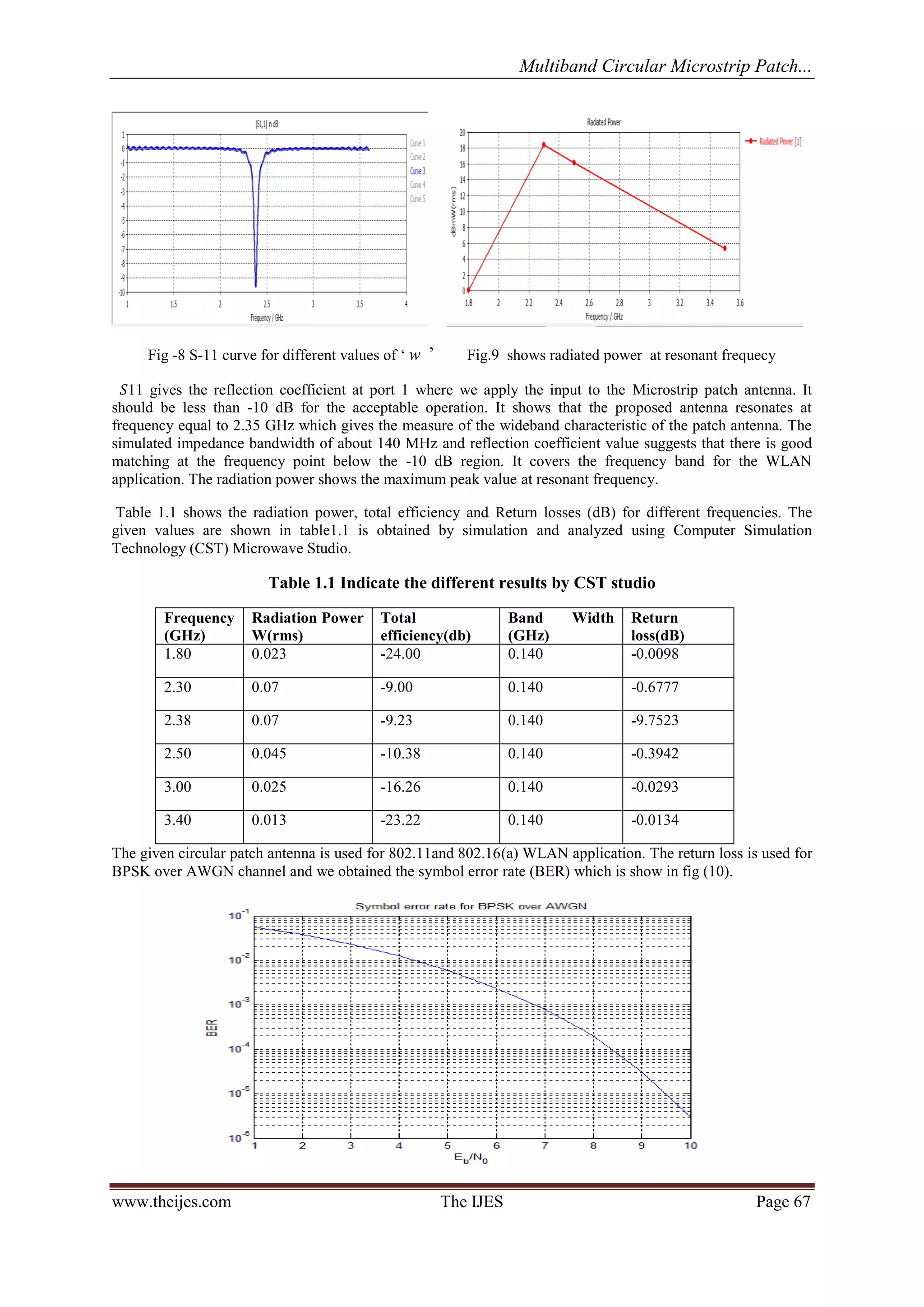
IV. SIMULATION RESULTS
Simulation studies of proposed antenna are carried out using CST Microwave Studio .The simulated
reflection coefficient 푆11 of the proposed antenna shown in dB. The scattering parameter 푆11 gives the
reflection coefficient at port 1 where we apply the input to the Microstrip patch antenna. It should be less than -
10 dB for the acceptable operation. It shows that the proposed antenna resonates at frequency equal to 2.344
GHz which gives the wideband characteristic of the patch antenna. The simulator shows the bandwidth of about
140 MHz (2.34-2.48 GHz) which is achieved at -10 dB reflection coefficient (VSWR≤2) [3]. The reflection
coefficient value that is achieved at this resonant frequency is equal to -23.901 dB. This reflection coefficient
value suggests that there is good matching at the frequency point below the -10 dB region. It covers the
frequency band for the WLAN application.
Fig. 6 3D Radiation pattern for 푓푟=2.3 GHz
Radiation pattern is a graphical representation of the relative field strength that can transmit or received by the
antenna. The antenna should not have the side lobes and back lobes .Ideally lobe is defined as a roundish and
flattish projecting or hanging part of patch surface. We can minimize them but we cannot remove them
completely. Figure 6 shows the simulated 3-D radiation pattern with directivity of 7.061 dBi for proposed
antenna configuration at the resonating frequency of 2.314 GHz.
Fig. 7(a) E-plane with theta phase Fig. 7(b) H-plane with phi phase
Figure 7(a) and (b) show the simulated E-plane (phi=90º, theta=varying) and H-plane (theta=90º, phi=varying)
radiation patterns for proposed antenna configuration at the resonating frequency of 2.314 GHz.](https://image.slidesharecdn.com/h0384064068-140902051704-phpapp01/75/Multiband-Circular-Microstrip-Patch-Antenna-for-WLAN-Application-3-2048.jpg)
![Multiband Circular Microstrip Patch...
www.theijes.com The IJES Page 68
Fig 10 BER plotation of circular patch antenna using AWGN channel
V. CONCLUSION
In this paper, a suspended configuration of circular patch antenna with coaxial feed is introduced to obtain a wideband characteristic. By optimizing the antenna parameters, concludes a wide impedance bandwidth of 2.34-2.48 GHz. The structure of the antenna is simple which helps in 802.11 and 802.16(a) WLAN application. The simulated and measured results show that the bandwidth of the patch antenna is successfully broadened; the proposed antenna shows the better performance in higher data rate for communications requiring circular polarizations. The designed antenna has future growth in OFDM and WLAN systems. REFERENCES [1] S. Chaimool, K. L. Chung, "CPW-fed mirrored-L monopole antenna with distinct triple bands for WiFi and WiMAX applications," Electron. Lett., vol. 45,no. 18, pp. 928-929, Aug. 2009. [2] J. H. Lu, B. J. Huang, "Planar multi-band monopole antenna with L-shaped parasitic strip for WiMAX application," Electron. Lett., vol. 46, no. 10, pp. 671- 672, May 2010. [3] L. Boccia, I. Russo, G. Amendola, G. Di Massa, “Varactor tuned Frequency Selective Surface for beam steering applications”, IEEE Antennas and Propagation Society International Symposium (APSURSI), pp. 1 – 4, 2010 [4] B. J. Kwaha, O. N Inyang & P. Amalu, “The circular Microstrip patch Antenna-Design and Implementation”, IJRRAS,vol. 18,no.8 ,pp 1~11,July-2011 [5] Seung Hyun Lee․Young-Je Sung ,” A Compact Triple Band Antenna for a Wireless USB Dongle ,” Journal of Electromagnetic Engineering and Science ,vol. 12, no. 2, pp185~188, Jun. 2012. [6] Z.Y. Zong, R.Xu, C. Chen, W. Wu, “Miniaturized Dualband Loaded Frequency Selective Surfaces with Close Band Spacing”, IEEE Asia-Pacific Microwave Conference APMC, pp.1 – 4, 2008. [7] H.Liu,K.L.Ford,R.JLangley ,”Miniaturized dualband loaded frequency selective surfaces with close band spacing”, Electronics Letters, vol. 44, Issue 18, pp. 1054-1055, 2008. [8] H. Liu, K. L. Ford, and R. J. Langley, “Novel Planar Band Pass Lump-Loaded Frequency Selective Surface”, IEEE MTT-S International Microwave Workshop Series on Art of Miniaturizing RF and Microwave Passive Components, pp. 87 – 89, 2008. [9] F.Bayatpur and K. Sarabandi “Tuning Performance of Metamaterial-Based Frequency Selective Surfaces”, IEEE Trans. Antennas Propag., vol. 57, no. 2, Feb. 2009. AUTHORS PROFILE
Mr Jaijit singh received B.E Degree in Electronics and Telecommunication Engineering From Institute of Electronics and Telecommunication engineering, Delhi in 2003. Currently he is pursuing M.Tech. degree in ECE Stream from Guru Gobind Singh Indraprasthe University , Delhi. His Research interest include Antenna design, Image processing VLSI Design.](https://image.slidesharecdn.com/h0384064068-140902051704-phpapp01/75/Multiband-Circular-Microstrip-Patch-Antenna-for-WLAN-Application-5-2048.jpg)


