Download to read offline
![International Research Journal of Engineering and Technology (IRJET) e-ISSN: 2395-0056
Volume: 06 Issue: 06 | June 2019 www.irjet.net p-ISSN: 2395-0072
© 2019, IRJET | Impact Factor value: 7.211 | ISO 9001:2008 Certified Journal | Page 114
Microstrip Patch Antenna Design for Military Applications
CH. S. Srinivas1, Damaraju Sri Sai Satyanarayana2
1UG Research Scholar, Dept. of Electronics and Communication Engineering, Sreyas Institute of Engineering and
Technology, Telangana, India
2UG Research Scholar, Dept. of Electronics and Communication Engineering, Sreyas Institute of Engineering and
Technology, Telangana, India
-------------------------------------------------------------------------***------------------------------------------------------------------------
Abstract:- In recent days the design and development of antennas for various applications has grabbed attention and
interest of various technocrats which is highly remarkable. This has led to the development of various techniques which has
improvised the electrical parameters like Gain, Bandwidth, Directivity etc., of the antennas. The square shape will provide the
broad bandwidth, which is required in various applications like remote sensing, biomedical application. This project aims to
study various electrical performance parameters related to antennas and develop the E-shaped patch antenna which will
operate for microwave applications. The entire design and analytical studies will be carried out in Computer Simulation Tool
(CST).
Keywords: Communication, Gain, Efficiency, Antenna Bandwidth, Directivity
1. INTRODUCTION TO ANTENNAS
Conventional microstrip patch antennas have many limitations such bandwidth, return loss, single input frequency, and
gain and polarization etc.; to overcome these problems a conventional E-patch antenna is designed with the frequency of
2.54GHz which is S-band. The S-band is used in mobile frequency applications. To implement this design many microstrip
feeding techniques are can be used. The basic E-patch antenna consists of 4 layers they are ground, substrate, patch and
feedline. The main application of these are used in military areas and other fields like GPS, LAN, Wi-Fi.
2. RELATED WORK
I. Sung, Y. J et al.,[1] This paper describes of a square patch antenna with an input impedance bandwidth of
2.2GHz-2.45 GHz for wireless applications. In this a dual feed generate mode patch is used as a starting point for
circular polarization and L-shaped islands to connect or reconnect main patch via RF switches are placed around
the patch.
II. Chen, Shing-Hau et al.,[2] This paper describes of a single feed reconfigurable square ring patch antenna with a
pattern diversity present in it. The structure of antenna has four shorting walls placed and connected directly to
patch and others are connected to the patch via pins diodes. By controlling the patch two modes are operated
that are monopolar and normal patch mode by this a -10db impedance is been overlapped in two modes.
III. Yang, Fan et al.,[3] This paper describes of an microstrip antenna with a switchable slot to achieve circular
polarization diversity to design these two orthogonal slots are incorporated into the patch and pin diodes are
used to on and off the slots and using this left and right circular polarizations are determined.
IV. Singhal, P. K et al.,[4] This paper describes a double layer slotted patch microstrip patch antenna with a single
probe feeding technique to lower patch with an input impedance of 6.1GHz for VSWR value of less than 2
(VSWR≤ 2). The result is it has a bandwidth of 6.25%.
3. CST STUDIO SUITE
The CST STUDIO SUITE is an electromagnetic stimulation tool which is used to analyze, design and stimulate different
types of antennas. The CST studio suite is also used optimize devices and systems at all stages of development of antennas.
The CST studio is used in different industries, automotive, aerospace etc. The CST is a virtual prototype. By using these
prototypes instead of physical prototypes engineers can study the prototypes in the earliest stages of design and reduce
the physical models that needed to construct and by using this we can reduce the wastage of materials and design an ideal
model without wasting any materials. The other main advantage of this prototypes is cost of antennas can be estimated
and be reduced by using various materials.](https://image.slidesharecdn.com/irjet-v6i621-191029043950/75/IRJET-Microstrip-Patch-Antenna-Design-for-Military-Applications-1-2048.jpg)
![International Research Journal of Engineering and Technology (IRJET) e-ISSN: 2395-0056
Volume: 06 Issue: 06 | June 2019 www.irjet.net p-ISSN: 2395-0072
© 2019, IRJET | Impact Factor value: 7.211 | ISO 9001:2008 Certified Journal | Page 115
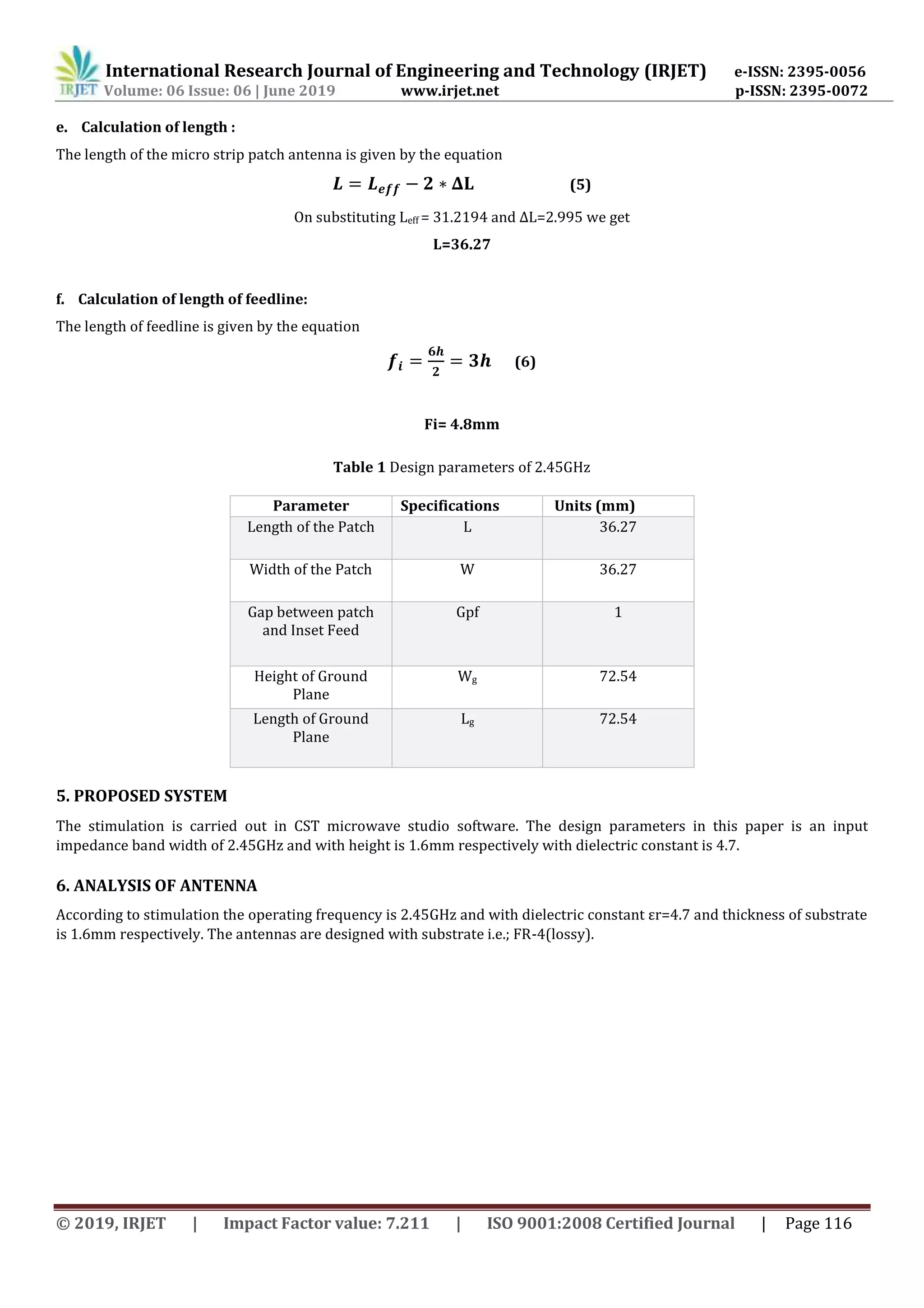
4. DESIGN EQUATIONS FOR ANTENNA
Both the antennas can be design by using following equations. By using these equations, we can easily find out the values
for dimensions of E shape patch.
a. Calculation of Width:
The width of the micro strip patch antenna is given by the equation
W=
√
(1)
on substituting, C=3*108 m/sec , fo= 2.4 GHz , we get
W= 36.2789
b. Calculation of Effective Dielectric Constant:
The calculation of effective dielectric constant of micro strip patch antenna is given by the equation
ɛreff = [1+12 ]-1/2 (2)
on substituting h=1.6mm, w=mm, er=4.7, we get
ɛreff = 3.84591
c. Calculation of Effective Length:
The calculation of effective length of the micro strip antenna is given by the equation
Leff =
√
(3)
On substituting c=3*108, f0=2.45 GHz , ɛreff=4.7mm,we get
Leff=31.2194
d. Calculation of Length extension:
The calculation of effective length of the micro strip antenna is given by the equation
(4)
On substituting h=1.6mm, w= 36.2789mm,
ɛreff = 3.84591, we get
ΔL= 2.995](https://image.slidesharecdn.com/irjet-v6i621-191029043950/75/IRJET-Microstrip-Patch-Antenna-Design-for-Military-Applications-2-2048.jpg)
![International Research Journal of Engineering and Technology (IRJET) e-ISSN: 2395-0056
Volume: 06 Issue: 06 | June 2019 www.irjet.net p-ISSN: 2395-0072
© 2019, IRJET | Impact Factor value: 7.211 | ISO 9001:2008 Certified Journal | Page 117
Figure 1 E-patch antenna layout [5]
A. Patch antenna design for frequency 2.45GHz:
In this patch antenna, the antenna is fed with operating frequency of 2.45GHz with dielectric constant (FR-4 lossy) εr =4.7
with height of substrate h=1.6mm basing on these design parameters square patch antenna design formulas are used and
following table is obtained.
Figure 2 Proposed Antenna Design for 2.45GHz
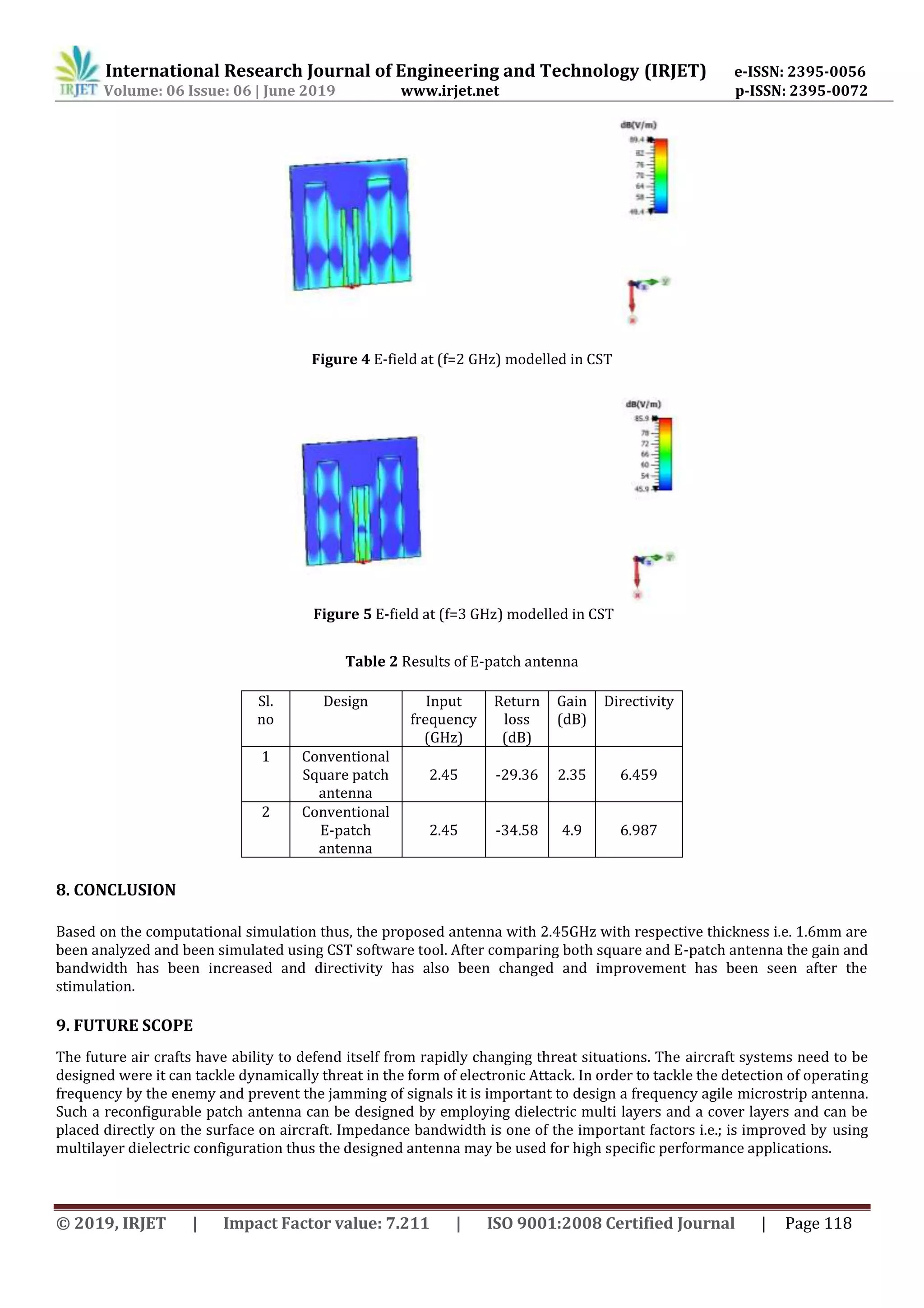
7. RESULTS & ANALYSIS
Figure 3 S-Parameters measurements of 2.45 GHz](https://image.slidesharecdn.com/irjet-v6i621-191029043950/75/IRJET-Microstrip-Patch-Antenna-Design-for-Military-Applications-4-2048.jpg)
![International Research Journal of Engineering and Technology (IRJET) e-ISSN: 2395-0056
Volume: 06 Issue: 06 | June 2019 www.irjet.net p-ISSN: 2395-0072
© 2019, IRJET | Impact Factor value: 7.211 | ISO 9001:2008 Certified Journal | Page 119
REFERENCES
[1] Babu, Jagadeesh & Rama Krishna, Kalva & Dr.L.Pratap, Reddy. “A Modified E Shaped Patch Antenna For Mimo Systems”.
International Journal on Computer Science and Engineering. 2.(2010).
[2] Sung, Y. J. "Reconfigurable patch antenna for polarization diversity." IEEE Transactions on antennas and propagation
56.9 (2008): 3053-3054.
[3] Chen, Shing-Hau, Jeen-Sheen Row, and Kin-Lu Wong. "Reconfigurable square-ring patch antenna with pattern
diversity." IEEE Transactions on Antennas and Propagation 55.2 (2007): 472-475.
[4] Yang, Fan, and Yahya Rahmat-Samii. "A reconfigurable patch antenna using switchable slots for circular polarization
diversity." IEEE Microwave and Wireless Components Letters 12.3 (2002): 96-98.
[5] Singhal, P. K., Bhawana Dhaniram, and Smita Banerjee. "A stacked square patch slotted broadband microstrip antenna."
Journal of Microwaves, Optoelectronics and Electromagnetic Applications (JMOe) 3.2 (2003): 60-66](https://image.slidesharecdn.com/irjet-v6i621-191029043950/75/IRJET-Microstrip-Patch-Antenna-Design-for-Military-Applications-6-2048.jpg)

The document describes the design of an E-shaped microstrip patch antenna for military applications operating at 2.54GHz (S-band). It discusses the design process, including calculating the antenna dimensions based on design equations. A prototype antenna was modeled in CST simulation software using FR-4 substrate. Simulation results showed the E-shaped patch antenna achieved improved gain and bandwidth compared to a conventional square patch antenna. Potential applications of the antenna include wireless communications and the antenna design could be further optimized for frequency agility.


