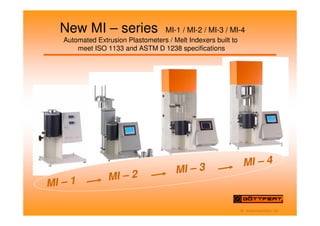
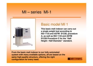
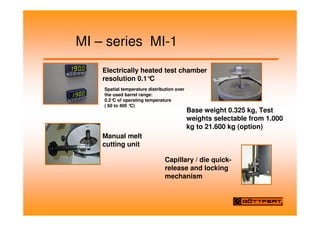
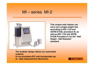
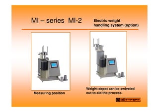
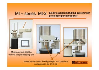
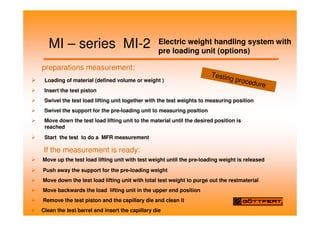
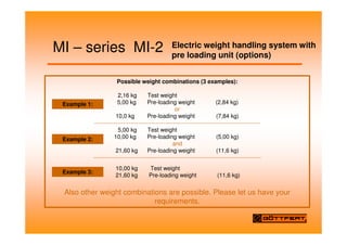
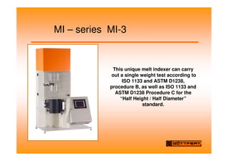
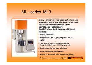
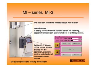
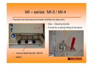
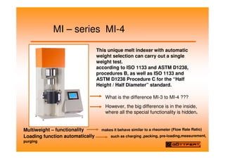
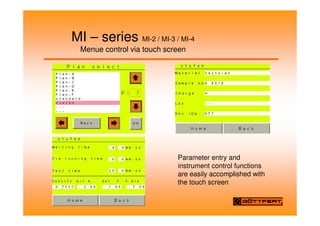
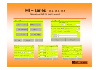
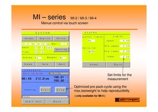
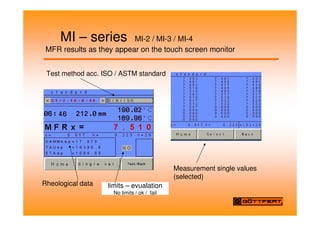
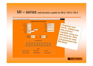
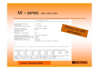
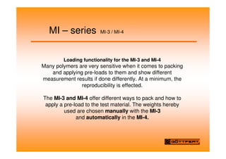
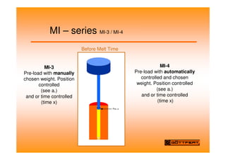
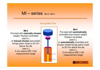
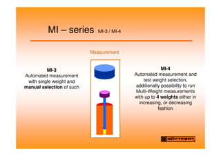
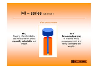
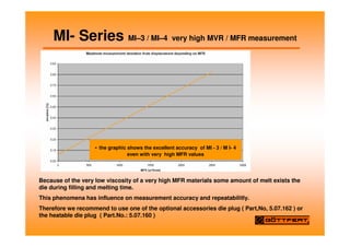
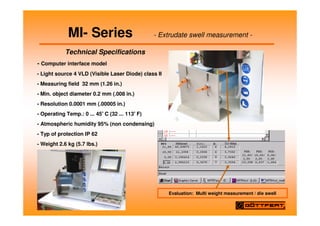
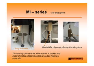
M. AckermannDec. 05
New MI – series MI-1 / MI-2 / MI-3 / MI-4
Automated Extrusion Plastometers / Melt Indexers built to
meet ISO 1133 and ASTM D 1238 specifications
MI – 1 MI – 2 MI – 3 MI – 4
MI – series MI-1
Basic model MI 1
This basic melt indexer can carry out
a single weight test according to
ISO 1133 and ASTM D1238, procedure
A, as well as ISO 1133 and ASTM
D1238 Procedure C for the “Half
Height / Half Diameter” standard.
From the basic melt indexer to our fully automated
system with many available options, all are based on the
same high-quality structure, offering the right
configuration for every need.
MI – series MI-1
Electrically heated test chamber
resolution 0.1°
C
Base weight 0.325 kg, Test
weights selectable from 1.000
kg to 21.600 kg (option)
Spatial temperature distribution over
the used barrel range:
0.2°
C of operating temperature
( 60 to 400 °
C)
Manual melt
cutting unit
Capillary / die quick-
release and locking
mechanism
MI – series MI-2
This unique melt indexer can
carry out a single weight test
according to ISO 1133 and
ASTM D1238, procedure B, as
well as ISO 1133 and ASTM
D1238 Procedure C for the “Half
Height / Half Diameter”
standard.
The modular design allows our automated
systems
to run procedure B/C and incorporates up-
to - date measurement electronics.
MI – series MI-2 Electric weight
handling system (option)
Measuring position
Weight depot can be swiveled
out to aid the process.
MI – series MI-2 Electric weight handling system with
pre-loading unit (options)
Measurement 5.00 kg
without the pre-loading unit
Measurement with 5.00 kg weight and previous
compression by 21.6 kg
MI – series MI-2 Electric weight handling system with
pre loading unit (options)
preparations measurement:
Loading of material (defined volume or weight )
Insert the test piston
Swivel the test load lifting unit together with the test weights to measuring position
Swivel the support for the pre-loading unit to measuring position
Move down the test load lifting unit to the material until the desired position is
reached
Start the test to do a MFR measurement
If the measurement is ready:
Move up the test load lifting unit with test weight until the pre-loading weight is released
Push away the support for the pre-loading weight
Move down the test load lifting unit with total test weight to purge out the restmaterial
Move backwards the load lifting unit in the upper end position
Remove the test piston and the capillary die and clean it
Clean the test barrel and insert the capillary die
Testing procedure
MI – series MI-2 Electric weight handling system with
pre loading unit (options)
Possible weight combinations (3 examples):
2,16 kg Test weight
5,00 kg Pre-loading weight (2,84 kg)
or
10,0 kg Pre-loading weight (7,84 kg)
---------------------------------------------------------------------------------------
5,00 kg Test weight
10,00 kg Pre-loading weight (5,00 kg)
and
21,60 kg Pre-loading weight (11,6 kg)
----------------------------------------------------------------------------------------
10,00 kg Test weight
21,60 kg Pre-loading weight (11,6 kg)
Also other weight combinations are possible. Please let us have your
requirements.
Example 1:
Example 2:
Example 3:
MI – series MI-3
This unique melt indexer can carry
out a single weight test according to
ISO 1133 and ASTM D1238,
procedure B, as well as ISO 1133 and
ASTM D1238 Procedure C for the
“Half Height / Half Diameter”
standard.
MI – series MI-3
Guided test piston
Base weight 1.200 kg, (1.000 kg and 1.050 kg
option)
Test weights from 2.160 kg to 21.600 kg
integrated (12.50 kg or 15.00 kg optional)
into the machine and user selectable
Electric weight handling system
Manual or automated melt cutting unit (option)
Extrudate swell measurement (option)
Every component has been optimized and
integrated into a new platform for superior
performance and maximum user-
friendliness. Furthermore,
the MI-3 offers the following additional
features:
MI – series MI-3
The user can select the needed weight with a lever.
Test chamber
is easily accessible from top and below for cleaning,
especially since it can be swiveled out to aid the process.
Die quick release and locking mechanism
Brilliant 5.7“ Color-
QVGA Touch screen
display for the
operation, program
control and display of
the measurement
results
MI – series MI-3 / MI-4
Practical and well placed toolholder facilitate the daily work
manual cleaning–set barrel
piston
Dies - Cleaning tool die
Funnel for a optimal filling of the barrel
MI – series MI-4
This unique melt indexer with automatic
weight selection can carry out a single
weight test.
according to ISO 1133 and ASTM D1238,
procedures B, as well as ISO 1133 and
ASTM D1238 Procedure C for the “Half
Height / Half Diameter” standard.
Multiweight – functionality makes it behave similar to a rheometer (Flow Rate Ratio)
Loading function automatically such as charging ,packing, pre-loading,measurement,
purging
What is the difference MI-3 to MI-4 ???
However, the big difference is in the inside,
where all the special functionality is hidden.
MI – series MI-2 / MI-3 / MI-4
Menue control via touch screen
Parameter entry and
instrument control functions
are easily accomplished with
the touch screen
MI – series MI-2 / MI-3 / MI-4
Menue control via touch screen
MI – series MI-2 / MI-3 / MI-4
Menue control via touch screen
Set limits for the
measurement
Optimized pre pack-cycle using the
max.testweight to help reproductibilty
( only available for MI-4 )
MI – series MI-2 / MI-3 / MI-4
MFR results as they appear on the touch screen monitor
limits – evualation
No limits / ok / fail
Test method acc. ISO / ASTM standard
Rheological data
Measurement single values
(selected)
MI – series web browser usable for MI-2 / MI-3 / MI-4
integrated web-
server, display and
data printout
available using any
web-browser. Data
can easily be used
and processed with
MS Office
MI – series MI-2 / MI-3 / MI-4
Printout via USB
connection
- incluce rheological data
MI – series MI-3 / MI-4
Loading functionality for the MI-3 and MI-4
Many polymers are very sensitive when it comes to packing
and applying pre-loads to them and show different
measurement results if done differently. At a minimum, the
reproducibility is effected.
The MI-3 and MI-4 offer different ways to pack and how to
apply a pre-load to the test material. The weights hereby
used are chosen manually with the MI-3
and automatically in the MI-4.
MI – series MI-3 / MI-4
Pos. a
MI-3
Pre-load with manually
chosen weight. Position
controlled
(see a.)
and or time controlled
(time x)
MI-4
Pre-load with automatically
controlled and chosen
weight. Position controlled
(see a.)
and or time controlled
(time x)
Before Melt Time
MI – series MI-3 / MI-4
Pos. c
Pos. b
MI-3
Pre-load with manually chosen
weight. Position controlled
(see b.),
or manual chosen test weight
brings piston head to 55 mm
above the die
(see c.),
5 mm above DIN 1133
measurement range
MI-4
Pre-load with automatically
controlled and chosen weight.
Position controlled
(see b.),
or automatically controlled and
chosen weight brings piston head
to 55 mm above the die
(see c.),
5 mm above DIN 1133
measurement range
during Melt Time
MI – series MI-3 / MI-4
MI-3
Automated measurement
with single weight and
manual selection of such
MI-4
Automated measurement and
test weight selection,
additionally possibility to run
Multi-Weight measurements
with up to 4 weights either in
increasing, or decreasing
fashion
Measurement
MI – series MI-3 / MI-4
MI-3
Purging of material after
the measurement with a
manually selectable test
weight
MI-4
Automated purging
of material with a
pre-programmed and
freely selectable test
weight.
after Measurement
MI – series - MFR Host - Software (optional)
MI-2 / MI-3 / MI-4
MVR / MFR single values and long-term graphics
Data Link
via
RS232 /
Ethernet
MI – series multi weight measurement MI-4
MI – series MVR / MFR range
Manual measurements with the above mentioned type can be recommend up to a
MFR 50 g / 10 min. by higher values the manual procedure is not accuray enough.
The ASTM – Norm recommend to select the weights in such a way, that the MFR is in
a range of 0.15g – 50g / 10 min.
MI – 2 MVR range up to 300 ccm/10 min.
MI – 3 / MI - 4 MVR Range up to 2500ccm/10 min or even
That is possible if the die was closed during the filling of the barrel and during
the melting time. To handle a measurement with values in this high MVR range
required experience of the operator.
The ASTM standard recommends by MVR value higher than 75 ccm / min to
use the Half die ( 4 / 1,048 ) .
The MVR value is reduced thereby by the eightfold.
Within the lower range there are none delimitation here is that the maximum
gate time by 25 minutes is not exceeded, and which must be present
according to the ISO Norm after 5 minutes and the ASTM standard after 7
minutes the first measuring point.
With the high resolution mode of the transducer it´s possible to measure MVR
smaller than 0.01 ccm/10 min.(attention max. testtime 25 minutes)
MI – 1 MFR range up to 50 g / 10 min.
MI- Series MI–3 / MI–4 very high MVR / MFR measurement
Because of the very low viscosity of a very high MFR materials some amount of melt exists the
die during filling and melting time.
This phenomena has influence on measurement accuracy and repeatabilitly.
Therefore we recommend to use one of the optional accessories die plug ( Part,No, 5.07.162 ) or
the heatable die plug ( Part.No.: 5.07.160 )
MI- Series MI–3 / MI–4 very high MVR / MFR measurement
- the graphic shows the excellent accuracy of MI - 3 / M I- 4
even with very high MFR values
MI- Series - Extrudate swell measurement -
Technical Specifications
- Computer interface model
- Light source 4 VLD (Visible Laser Diode) class II
- Measuring field 32 mm (1.26 in.)
- Min. object diameter 0.2 mm (.008 in.)
- Resolution 0.0001 mm (.00005 in.)
- Operating Temp.: 0 ... 45


 C (32 ... 113


 F)
- Atmospheric humidity 95% (non condensing)
- Typ of protection IP 62
- Weight 2.6 kg (5.7 lbs.)
Evaluation: Multi weight measurement / die swell
MI – series - Die
ie plug
plug option
option -
-
To manually close the die while system is packed and
material melted. Recommended for certain high flow
materials.
Heated Die plug controlled by the Mi-system
- Easy to handle -
Summary of features
- Display
- Brilliant 5.7“ Color-QVGA Touch
screen display for operation
- Clearly arrangend and
userfriendly
- 6 most frequently testplan
directly selectable, storage of 50
testplan possible
- Connection of MFR - Hostprogram
- define different user levels
Summary of features
- temperature
Two heater elements / zones:
Precise temperature display
Resolution via 16 Bit A/D converter 0 to 320°
C: 0.01°
C,
320 to 500°C: 0.1°
C (option)
Spatial temperature distribution over the used barrel range
(0 - 70mm before the die):
0.2°
C ( 60 … 400 °
C)
0.3°
C ( 400…500 °C) (option)
5 Calibration settings for set temperatures
Summary of features
- measurement
Measurements acc. ISO / ASTM norm
Measuring section is additional free selectable
Digital encoder, resolution 0.006 mm / impulse
High precision timer / resolution  0.001s
Pre-loading unit MI – 2
Loading functionality for the MI-3 and MI-4
High reproducebiltity of measurements
Multiweight Measurement with increased /decreased
weight order
FRR – evaluation ( flow rate ratio)
Results comparable with type MP-D / MP-X
Summary of features
- general
Built-in USB-connection (Data Stick) for data back-up
USB printer port
Serial connection to communicate with the MFR Host
software or the optional scale
Ethernet - connection (LAN, TCP/IP FTP, VNC,
WEB-Server)
Integrated Web-Server
Summary of features
- options
Manual or automated melt cutting unit
Die plug (standard / heatable)
Nitrogen purge
Extrudate swell measurement
Short capillary 4 / 1,048 available for procedure C
Scale (automatic determination of the melt density)
Pneumatic cleaning device
Inconel Barrel set (corrosion constant design)

Gootfert MI 2-3-4 description.pdf

  • 1.
    M. AckermannDec. 05 NewMI – series MI-1 / MI-2 / MI-3 / MI-4 Automated Extrusion Plastometers / Melt Indexers built to meet ISO 1133 and ASTM D 1238 specifications MI – 1 MI – 2 MI – 3 MI – 4
  • 2.
    MI – seriesMI-1 Basic model MI 1 This basic melt indexer can carry out a single weight test according to ISO 1133 and ASTM D1238, procedure A, as well as ISO 1133 and ASTM D1238 Procedure C for the “Half Height / Half Diameter” standard. From the basic melt indexer to our fully automated system with many available options, all are based on the same high-quality structure, offering the right configuration for every need.
  • 3.
    MI – seriesMI-1 Electrically heated test chamber resolution 0.1° C Base weight 0.325 kg, Test weights selectable from 1.000 kg to 21.600 kg (option) Spatial temperature distribution over the used barrel range: 0.2° C of operating temperature ( 60 to 400 ° C) Manual melt cutting unit Capillary / die quick- release and locking mechanism
  • 4.
    MI – seriesMI-2 This unique melt indexer can carry out a single weight test according to ISO 1133 and ASTM D1238, procedure B, as well as ISO 1133 and ASTM D1238 Procedure C for the “Half Height / Half Diameter” standard. The modular design allows our automated systems to run procedure B/C and incorporates up- to - date measurement electronics.
  • 5.
    MI – seriesMI-2 Electric weight handling system (option) Measuring position Weight depot can be swiveled out to aid the process.
  • 6.
    MI – seriesMI-2 Electric weight handling system with pre-loading unit (options) Measurement 5.00 kg without the pre-loading unit Measurement with 5.00 kg weight and previous compression by 21.6 kg
  • 7.
    MI – seriesMI-2 Electric weight handling system with pre loading unit (options) preparations measurement: Loading of material (defined volume or weight ) Insert the test piston Swivel the test load lifting unit together with the test weights to measuring position Swivel the support for the pre-loading unit to measuring position Move down the test load lifting unit to the material until the desired position is reached Start the test to do a MFR measurement If the measurement is ready: Move up the test load lifting unit with test weight until the pre-loading weight is released Push away the support for the pre-loading weight Move down the test load lifting unit with total test weight to purge out the restmaterial Move backwards the load lifting unit in the upper end position Remove the test piston and the capillary die and clean it Clean the test barrel and insert the capillary die Testing procedure
  • 8.
    MI – seriesMI-2 Electric weight handling system with pre loading unit (options) Possible weight combinations (3 examples): 2,16 kg Test weight 5,00 kg Pre-loading weight (2,84 kg) or 10,0 kg Pre-loading weight (7,84 kg) --------------------------------------------------------------------------------------- 5,00 kg Test weight 10,00 kg Pre-loading weight (5,00 kg) and 21,60 kg Pre-loading weight (11,6 kg) ---------------------------------------------------------------------------------------- 10,00 kg Test weight 21,60 kg Pre-loading weight (11,6 kg) Also other weight combinations are possible. Please let us have your requirements. Example 1: Example 2: Example 3:
  • 9.
    MI – seriesMI-3 This unique melt indexer can carry out a single weight test according to ISO 1133 and ASTM D1238, procedure B, as well as ISO 1133 and ASTM D1238 Procedure C for the “Half Height / Half Diameter” standard.
  • 10.
    MI – seriesMI-3 Guided test piston Base weight 1.200 kg, (1.000 kg and 1.050 kg option) Test weights from 2.160 kg to 21.600 kg integrated (12.50 kg or 15.00 kg optional) into the machine and user selectable Electric weight handling system Manual or automated melt cutting unit (option) Extrudate swell measurement (option) Every component has been optimized and integrated into a new platform for superior performance and maximum user- friendliness. Furthermore, the MI-3 offers the following additional features:
  • 11.
    MI – seriesMI-3 The user can select the needed weight with a lever. Test chamber is easily accessible from top and below for cleaning, especially since it can be swiveled out to aid the process. Die quick release and locking mechanism Brilliant 5.7“ Color- QVGA Touch screen display for the operation, program control and display of the measurement results
  • 12.
    MI – seriesMI-3 / MI-4 Practical and well placed toolholder facilitate the daily work manual cleaning–set barrel piston Dies - Cleaning tool die Funnel for a optimal filling of the barrel
  • 13.
    MI – seriesMI-4 This unique melt indexer with automatic weight selection can carry out a single weight test. according to ISO 1133 and ASTM D1238, procedures B, as well as ISO 1133 and ASTM D1238 Procedure C for the “Half Height / Half Diameter” standard. Multiweight – functionality makes it behave similar to a rheometer (Flow Rate Ratio) Loading function automatically such as charging ,packing, pre-loading,measurement, purging What is the difference MI-3 to MI-4 ??? However, the big difference is in the inside, where all the special functionality is hidden.
  • 14.
    MI – seriesMI-2 / MI-3 / MI-4 Menue control via touch screen Parameter entry and instrument control functions are easily accomplished with the touch screen
  • 15.
    MI – seriesMI-2 / MI-3 / MI-4 Menue control via touch screen
  • 16.
    MI – seriesMI-2 / MI-3 / MI-4 Menue control via touch screen Set limits for the measurement Optimized pre pack-cycle using the max.testweight to help reproductibilty ( only available for MI-4 )
  • 17.
    MI – seriesMI-2 / MI-3 / MI-4 MFR results as they appear on the touch screen monitor limits – evualation No limits / ok / fail Test method acc. ISO / ASTM standard Rheological data Measurement single values (selected)
  • 18.
    MI – seriesweb browser usable for MI-2 / MI-3 / MI-4 integrated web- server, display and data printout available using any web-browser. Data can easily be used and processed with MS Office
  • 19.
    MI – seriesMI-2 / MI-3 / MI-4 Printout via USB connection - incluce rheological data
  • 20.
    MI – seriesMI-3 / MI-4 Loading functionality for the MI-3 and MI-4 Many polymers are very sensitive when it comes to packing and applying pre-loads to them and show different measurement results if done differently. At a minimum, the reproducibility is effected. The MI-3 and MI-4 offer different ways to pack and how to apply a pre-load to the test material. The weights hereby used are chosen manually with the MI-3 and automatically in the MI-4.
  • 21.
    MI – seriesMI-3 / MI-4 Pos. a MI-3 Pre-load with manually chosen weight. Position controlled (see a.) and or time controlled (time x) MI-4 Pre-load with automatically controlled and chosen weight. Position controlled (see a.) and or time controlled (time x) Before Melt Time
  • 22.
    MI – seriesMI-3 / MI-4 Pos. c Pos. b MI-3 Pre-load with manually chosen weight. Position controlled (see b.), or manual chosen test weight brings piston head to 55 mm above the die (see c.), 5 mm above DIN 1133 measurement range MI-4 Pre-load with automatically controlled and chosen weight. Position controlled (see b.), or automatically controlled and chosen weight brings piston head to 55 mm above the die (see c.), 5 mm above DIN 1133 measurement range during Melt Time
  • 23.
    MI – seriesMI-3 / MI-4 MI-3 Automated measurement with single weight and manual selection of such MI-4 Automated measurement and test weight selection, additionally possibility to run Multi-Weight measurements with up to 4 weights either in increasing, or decreasing fashion Measurement
  • 24.
    MI – seriesMI-3 / MI-4 MI-3 Purging of material after the measurement with a manually selectable test weight MI-4 Automated purging of material with a pre-programmed and freely selectable test weight. after Measurement
  • 25.
    MI – series- MFR Host - Software (optional) MI-2 / MI-3 / MI-4 MVR / MFR single values and long-term graphics Data Link via RS232 / Ethernet
  • 26.
    MI – seriesmulti weight measurement MI-4
  • 27.
    MI – seriesMVR / MFR range Manual measurements with the above mentioned type can be recommend up to a MFR 50 g / 10 min. by higher values the manual procedure is not accuray enough. The ASTM – Norm recommend to select the weights in such a way, that the MFR is in a range of 0.15g – 50g / 10 min. MI – 2 MVR range up to 300 ccm/10 min. MI – 3 / MI - 4 MVR Range up to 2500ccm/10 min or even That is possible if the die was closed during the filling of the barrel and during the melting time. To handle a measurement with values in this high MVR range required experience of the operator. The ASTM standard recommends by MVR value higher than 75 ccm / min to use the Half die ( 4 / 1,048 ) . The MVR value is reduced thereby by the eightfold. Within the lower range there are none delimitation here is that the maximum gate time by 25 minutes is not exceeded, and which must be present according to the ISO Norm after 5 minutes and the ASTM standard after 7 minutes the first measuring point. With the high resolution mode of the transducer it´s possible to measure MVR smaller than 0.01 ccm/10 min.(attention max. testtime 25 minutes) MI – 1 MFR range up to 50 g / 10 min.
  • 28.
    MI- Series MI–3/ MI–4 very high MVR / MFR measurement
  • 29.
    Because of thevery low viscosity of a very high MFR materials some amount of melt exists the die during filling and melting time. This phenomena has influence on measurement accuracy and repeatabilitly. Therefore we recommend to use one of the optional accessories die plug ( Part,No, 5.07.162 ) or the heatable die plug ( Part.No.: 5.07.160 ) MI- Series MI–3 / MI–4 very high MVR / MFR measurement - the graphic shows the excellent accuracy of MI - 3 / M I- 4 even with very high MFR values
  • 30.
    MI- Series -Extrudate swell measurement - Technical Specifications - Computer interface model - Light source 4 VLD (Visible Laser Diode) class II - Measuring field 32 mm (1.26 in.) - Min. object diameter 0.2 mm (.008 in.) - Resolution 0.0001 mm (.00005 in.) - Operating Temp.: 0 ... 45 C (32 ... 113 F) - Atmospheric humidity 95% (non condensing) - Typ of protection IP 62 - Weight 2.6 kg (5.7 lbs.) Evaluation: Multi weight measurement / die swell
  • 31.
    MI – series- Die ie plug plug option option - - To manually close the die while system is packed and material melted. Recommended for certain high flow materials. Heated Die plug controlled by the Mi-system - Easy to handle -
  • 32.
    Summary of features -Display - Brilliant 5.7“ Color-QVGA Touch screen display for operation - Clearly arrangend and userfriendly - 6 most frequently testplan directly selectable, storage of 50 testplan possible - Connection of MFR - Hostprogram - define different user levels
  • 33.
    Summary of features -temperature Two heater elements / zones: Precise temperature display Resolution via 16 Bit A/D converter 0 to 320° C: 0.01° C, 320 to 500°C: 0.1° C (option) Spatial temperature distribution over the used barrel range (0 - 70mm before the die): 0.2° C ( 60 … 400 ° C) 0.3° C ( 400…500 °C) (option) 5 Calibration settings for set temperatures
  • 34.
    Summary of features -measurement Measurements acc. ISO / ASTM norm Measuring section is additional free selectable Digital encoder, resolution 0.006 mm / impulse High precision timer / resolution 0.001s Pre-loading unit MI – 2 Loading functionality for the MI-3 and MI-4 High reproducebiltity of measurements Multiweight Measurement with increased /decreased weight order FRR – evaluation ( flow rate ratio) Results comparable with type MP-D / MP-X
  • 35.
    Summary of features -general Built-in USB-connection (Data Stick) for data back-up USB printer port Serial connection to communicate with the MFR Host software or the optional scale Ethernet - connection (LAN, TCP/IP FTP, VNC, WEB-Server) Integrated Web-Server
  • 36.
    Summary of features -options Manual or automated melt cutting unit Die plug (standard / heatable) Nitrogen purge Extrudate swell measurement Short capillary 4 / 1,048 available for procedure C Scale (automatic determination of the melt density) Pneumatic cleaning device Inconel Barrel set (corrosion constant design)