Download as PDF, PPTX
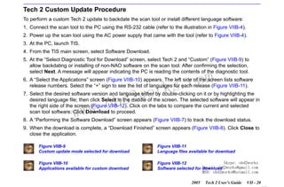
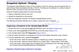
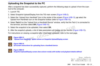
![RETURN TO MAIN MENU
SECTION III
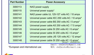
GETTING STARTED
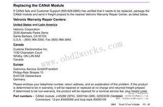
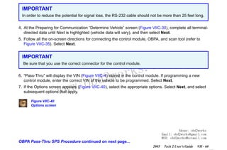
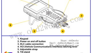
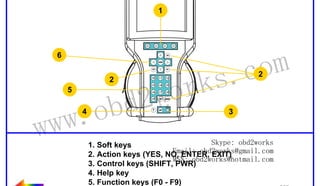
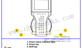
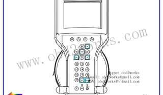
Tech 2 Keypad
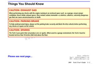
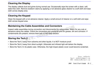
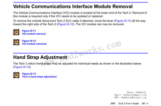
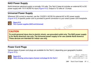
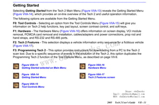
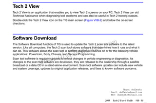
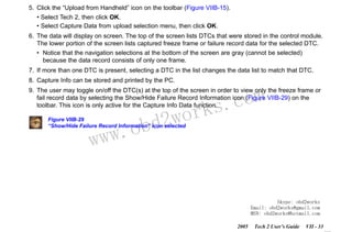
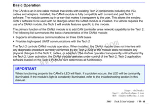
The Tech 2 keypad consists of six major keypad operation areas (Figure III-14):
1.
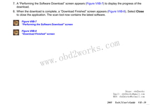
2.
3.
4.
5.
6.
Control keys (SHIFT, PWR)
Soft keys
Selection (arrow) keys
Action keys (YES, NO, ENTER, EXIT)
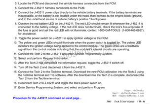
Function keys (F0 to F9)
Help (?) key
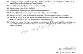
Control Keys
wor
bd2
com
s.
k
The [PWR] key is used to turn the Tech 2 on or off (Figure III-15). The status indicator light above this key
will be illuminated green when the Tech 2 is operational.
w.o
ww
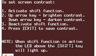
The [SHIFT] key is used with the up and down arrow keys to change screen brightness and contrast
(Figure III-15). To adjust screen brightness and contrast, perform the following:
• Press the [SHIFT] key once (amber status indicator light above [SHIFT] should light up).
• Use up and down arrows to adjust screen brightness and contrast:
Press up arrow key to increase screen brightness and contrast.
Press down arrow key to decrease screen brightness and contrast.
• Press [SHIFT] key again when desired brightness is reached (status indicator light above [SHIFT]
should now be off).
The Tech 2 should return to normal operation after following the above steps.
Figure III-14
Tech 2 keypad
Skype: obd2works
Figure III-15
Email: obd2works@gmail.com
Location of control keys obd2works@hotmail.com
MSN:
2005
Tech 2 User’s Guide
III - 5
www.xcar360.com](https://image.slidesharecdn.com/gmtech2usermanual-131126203939-phpapp01/85/Gm-tech-2-user-manual-21-320.jpg)
![RETURN TO MAIN MENU
SECTION III
GETTING STARTED
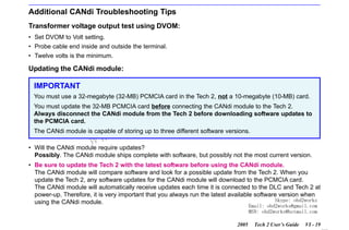
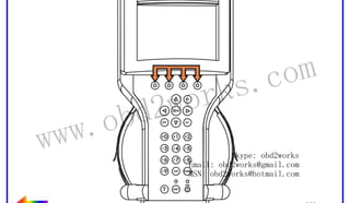
Soft Keys
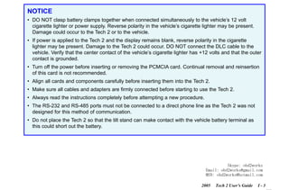
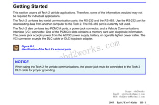
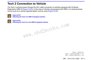
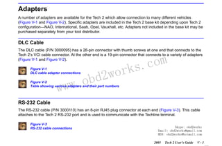
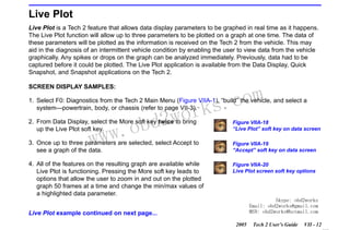
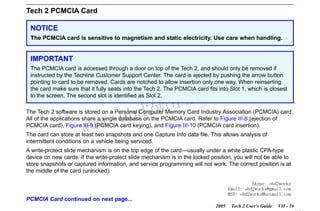
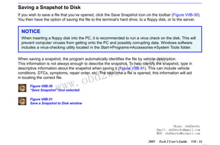
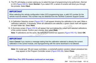
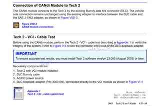
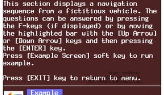
Four soft keys are located directly below the Tech 2 screen (Figure III-16). The soft keys correspond
directly to the four possible selection boxes found at the bottom region of the Tech 2 screen. These
selections may change from screen to screen and are under the control of the application software. To
make a screen selection, press the corresponding soft key. In the example shown in Figure III-17, the first
soft key was pressed to select [Display Time].
Figure III-16
Location of soft keys
Figure III-17
Soft key selection for display time
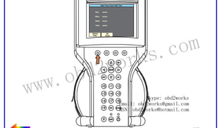
Selection Keys
w.o
ww
wor
bd2
com
s.
k
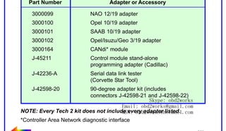
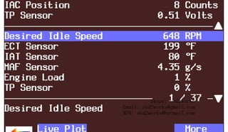
The Tech 2 selection keys are four directional arrow keys (Figure III-18). Press the arrow keys to move the
highlighted area to a selection on the screen (Figure III-19) or to scroll the screens if more than one. Once
the desired selection is highlighted, press [ENTER] to activate the selection.
Figure III-18
Location of selection keys
Figure III-19
Positioning the highlighted area to make a selection
Skype: obd2works
Email: obd2works@gmail.com
MSN: obd2works@hotmail.com
2005
Tech 2 User’s Guide
III - 6
www.xcar360.com](https://image.slidesharecdn.com/gmtech2usermanual-131126203939-phpapp01/85/Gm-tech-2-user-manual-22-320.jpg)
![RETURN TO MAIN MENU
SECTION III
GETTING STARTED
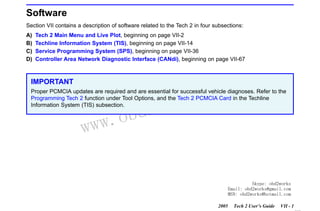
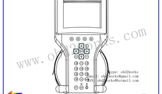
Action Keys
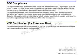
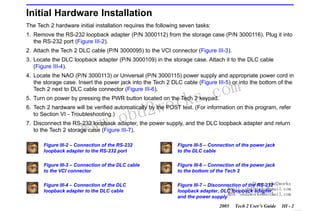
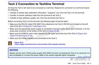
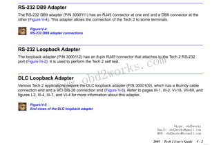
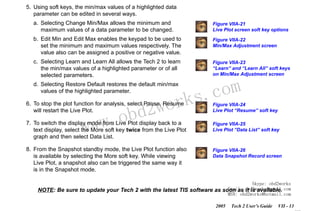
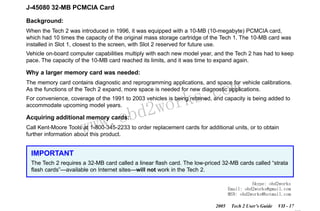
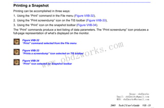
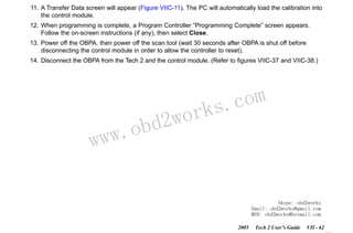
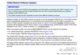
Action keys are used to respond to a specific question, initiate an action, or to exit from the Tech 2
program (Figure III-20). Specific “yes or no” questions will often appear on the Tech 2 screen. The [YES]
and [NO] keys are used to respond to these questions. Either of the two [ENTER] keys may be pressed to
activate a menu selection. Either of the two [EXIT] keys may be pressed to leave the current Tech 2
screen and return to a previous screen.
Figure III-20
Location of action keys
Function Keys
wor
bd2
com
s.
k
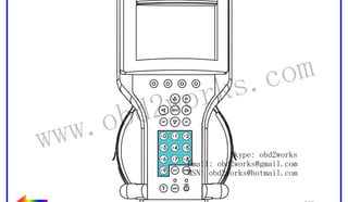
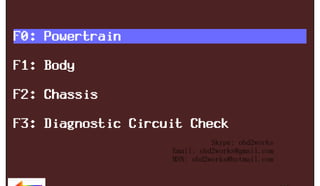
Ten function keys (F0 to F9) are located on the Tech 2 keypad (Figure III-21). A function key may be
pressed to initiate a specific Tech 2 function. In some cases the function keys are used for numeric data
entry. The arrow keys and [ENTER] may also be used to initiate a function selection, but this will require
multiple keystrokes as opposed to only one.
w.o
ww
Figure III-21
Location of function keys
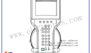
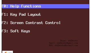
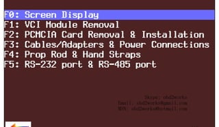
Help Key
The help key [?] may be pressed at any time to obtain a help screen (Figure III-22). The help screen will
provide specific information relating to the operation of the Tech 2.
Figure III-22
Location of help key
Skype: obd2works
Email: obd2works@gmail.com
MSN: obd2works@hotmail.com
2005
Tech 2 User’s Guide
III - 7
www.xcar360.com](https://image.slidesharecdn.com/gmtech2usermanual-131126203939-phpapp01/85/Gm-tech-2-user-manual-23-320.jpg)
![RETURN TO MAIN MENU
SECTION III
GETTING STARTED
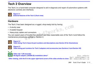
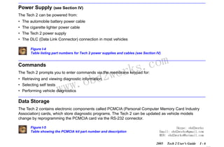
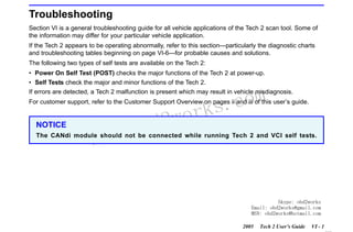
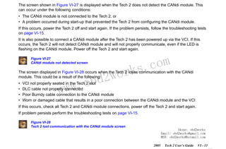
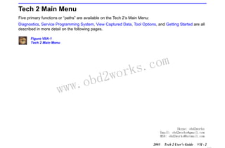
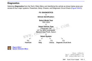
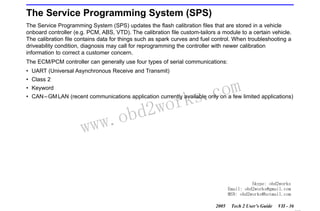
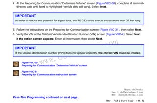
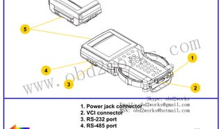
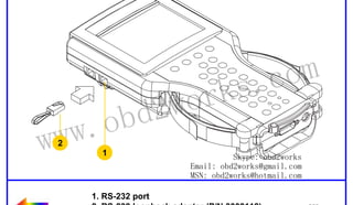
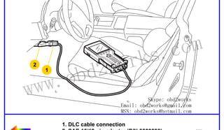
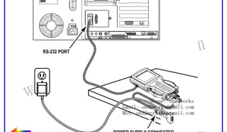
How to Connect the Tech 2 to a Computer Terminal
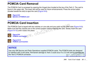
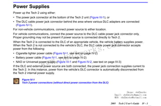
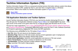
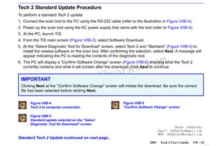
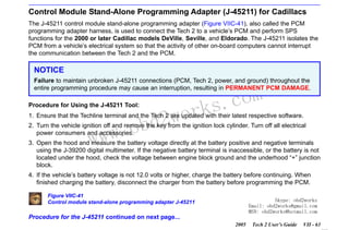
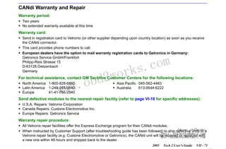
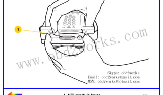
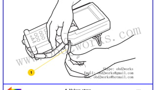
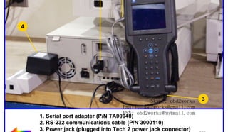
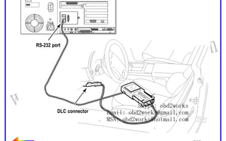
Follow the steps below and refer to Figure III-26, which illustrates the typical Tech 2 connection to a
computer terminal.
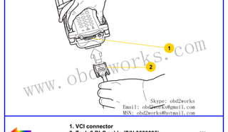
1. Plug the serial port adapter (P/N TA00040) into the serial port marked “A” or “1” on the back of the
computer terminal or to the USB port using the USB serial adapter.
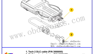
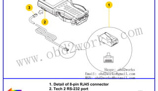
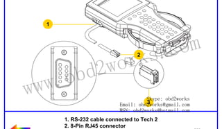
2. Plug the Tech 2’s RS-232 cable into the serial port / USB port adapter and connect the appropriate
power supply.
3. After power is supplied to the Tech 2 and the [PWR] button is pressed, the Tech 2 start-up display
should appear on the Tech 2 screen (Figure III-27).
Figure III-26
Typical Tech 2 connection to a computer terminal (rear view)
w.o
ww
wor
bd2
com
s.
k
Figure III-27
Tech 2 displaying the Tech 2 start-up screen
Skype: obd2works
Email: obd2works@gmail.com
MSN: obd2works@hotmail.com
2005
Tech 2 User’s Guide
III - 10
www.xcar360.com](https://image.slidesharecdn.com/gmtech2usermanual-131126203939-phpapp01/85/Gm-tech-2-user-manual-26-320.jpg)

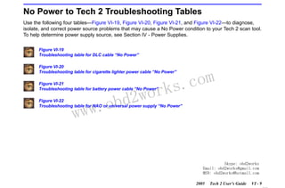
![RETURN TO MAIN MENU
SECTION VI
TROUBLESHOOTING
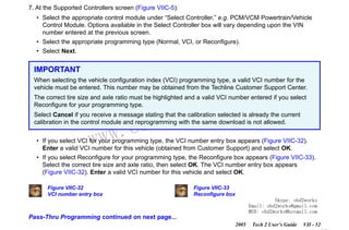
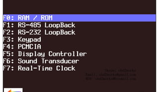
Power On Self Test (POST)
Power On Self Tests run automatically each time the power [PWR] button on the Tech 2 keypad is pressed
on. The screen displays pass or fail results for each area tested. POST automatically checks the following:
•
•
•
•
•
•
•
•
•
MC68332 processor
External RAM (Random Access Memory)
Flash memory
Display controller and display
Sound transducer
MC68332 RAM
Real-time clock
Keypad controller and keypad
Main UART (Universal Asynchronous Receiver/Transmitter)
wor
bd2
com
s.
k
Results of POST may include fatal errors that do not allow you to continue, or non-fatal errors that allow
you to continue without full Tech 2 operation. If normal Tech 2 functions are stopped or limited, contact
Customer Support to determine if service is required.
w.o
ww
At completion of POST, the following audible signals indicate a pass or fail condition:
• One beep - No problem. Your Tech 2 is operating normally.
• No beep - Sound transducer has failed. Contact Customer Support.
• Three short beeps - Tech 2 has failed POST. Contact Customer Support.
In the United States and Canada to contact Customer Support, dial:
•
•
•
•
English:
French:
Spanish:
Fax line:
1-800-828-6860 (option 1)
1-800-503-3222
1-248-265-0840 (option 2)
1-248-265-9327
Skype: obd2works
Email: obd2works@gmail.com
MSN: obd2works@hotmail.com
Refer to page iii for international customer support.
2005
Tech 2 User’s Guide
VI - 2
www.xcar360.com](https://image.slidesharecdn.com/gmtech2usermanual-131126203939-phpapp01/85/Gm-tech-2-user-manual-33-320.jpg)
![RETURN TO MAIN MENU
SECTION VI
TROUBLESHOOTING
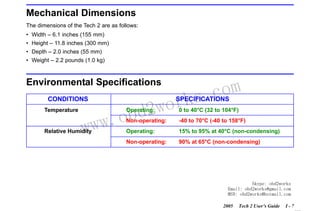
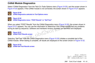
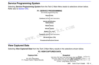
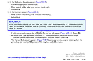
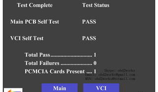
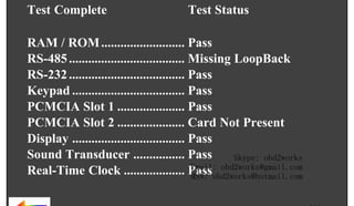
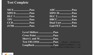
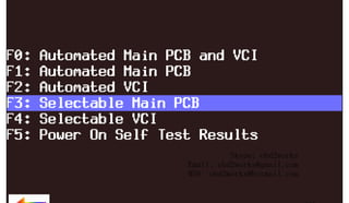
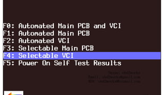
Tech 2 Self Tests
Tech 2 self tests verify that the Tech 2 is functioning normally. The self tests evaluate all critical areas of
the Tech 2 and display pass or fail messages for each subsystem tested. Self tests isolate user error from
system hardware failures. The self tests should be performed periodically to insure that the Tech 2 is
operating properly.
The Tech 2 must meet the following requirements in order to do a self test:
• Screen display must be fully readable
• Keypad must be operational
Begin the Tech 2 self-testing program by following these steps:
com
s.
k
1. Press [ENTER] while viewing the Tech 2 start-up screen (Figure VI-1).
wor
bd2
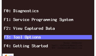
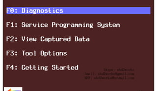
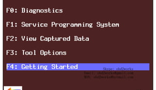
2. Select F3: Tool Options from the Tech 2 Main Menu (Figure VI-2).
w.o
ww
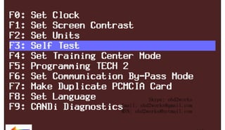
3. Select F3: Self Test from the Tool Options menu (Figure VI-3).
Figure VI-1
Tech 2 startup screen
Figure VI-2
Tools Options selected on Main Menu
Figure VI-3
Self Test selected on Tool Options menu
Skype: obd2works
Email: obd2works@gmail.com
MSN: obd2works@hotmail.com
2005
Tech 2 User’s Guide
VI - 3
www.xcar360.com](https://image.slidesharecdn.com/gmtech2usermanual-131126203939-phpapp01/85/Gm-tech-2-user-manual-34-320.jpg)


![RETURN TO MAIN MENU
SECTION VIIA
TECH 2 MAIN MENU & LIVE PLOT
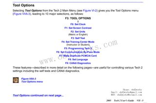
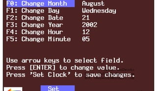
F0: Set Clock
After you select F0: Set Clock from the Tool Options menu (Figure VIIA-3) and the Set Real-Time Clock
menu (Figure VIIA-4) appears, you can set the internal Tech 2 real-time clock in two ways:
1. Use the up and down arrow keys to move the cursor to desired selection. Press [ENTER] to change the
value. Each time [ENTER] is pressed the value will be increased by one unit until a preset maximum
unit is reached. Once all correct values are entered, press the Set Clock soft key to save all changes.
2. Use the function key of the desired selection to change an incorrect value. Each time the function key is
pressed the value will be increased by one unit until a preset maximum is reached. Once all correct
values are entered, press the Set Clock soft key to save all changes.
Figure VIIA-4
Set Real-Time Clock menu
w.o
ww
wor
bd2
com
s.
k
Skype: obd2works
Email: obd2works@gmail.com
MSN: obd2works@hotmail.com
Tool Options continued on next page...
2005
Tech 2 User’s Guide
VII - 6
www.xcar360.com](https://image.slidesharecdn.com/gmtech2usermanual-131126203939-phpapp01/85/Gm-tech-2-user-manual-56-320.jpg)
![RETURN TO MAIN MENU
SECTION VIIA
TECH 2 MAIN MENU & LIVE PLOT
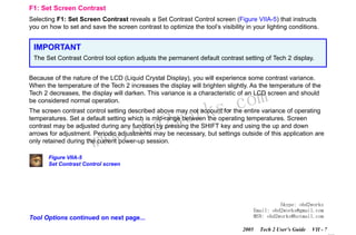
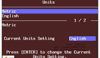
F2: Set Units
When you select the F2: Set Units option, a Set Units screen will appear (Figure VIIA-6). Use the up and
down arrow keys to change the Current Units Setting from English to Metric or vice versa, if desired. Press
[ENTER] to save your setting as the default.
Figure VIIA-6
Set Units screen
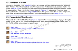
F3: Self Test
Selecting F3: Self Test gives you access to the Tech 2 Self Test menu screen (Figure VI-5), which will help
you to verify that the Tech 2 is functioning normally. Refer to Section VI - Troubleshooting for more
information on this area.
wor
bd2
com
s.
k
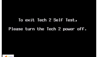
Power Down Screen. After completion of any Self Test, return to the Tech 2 Self Test menu screen. After
pressing [EXIT], a screen will appear instructing you to turn the Tech 2 power off (Figure VIIA-7). Turn off
the Tech 2 and turn back on to continue.
w.o
ww
Figure VIIA-7
Tech 2 power down screen
Skype: obd2works
Email: obd2works@gmail.com
MSN: obd2works@hotmail.com
Tool Options continued on next page...
2005
Tech 2 User’s Guide
VII - 8
www.xcar360.com](https://image.slidesharecdn.com/gmtech2usermanual-131126203939-phpapp01/85/Gm-tech-2-user-manual-58-320.jpg)
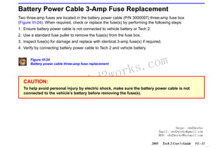
![RETURN TO MAIN MENU
SECTION VIIA
TECH 2 MAIN MENU & LIVE PLOT
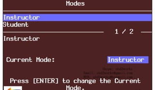
F4: Set Training Center Mode
After you select F4: Set Training Center Mode—for GM Training Centers only—a Set Training Center
Mode screen appears (Figure VIIA-8), giving you the ability to connect multiple Tech 2 scan tools for
instructional purposes.
Figure VIIA-8
Set Training Center Mode screen
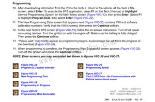
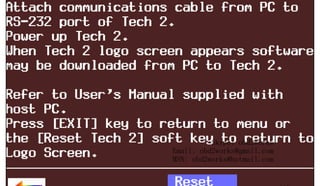
F5: Programming Tech 2
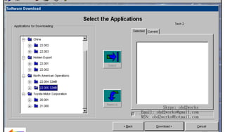
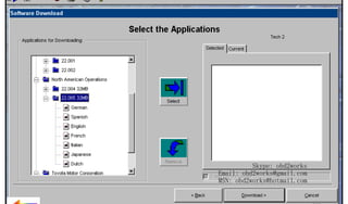
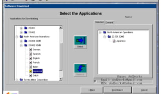
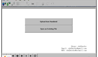
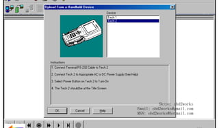
After you select F5: Programming Tech 2, you can follow the on-screen instructions (Figure VIIA-9) for
downloading from a PC to the Tech 2 scan tool via the RS-232 cable. Refer also to Software Download,
Tech 2 PCMCIA Card, and Tech 2 Update Procedure later in this section.
Figure VIIA-9
Programming Tech 2 screen
w.o
ww
wor
bd2
com
s.
k
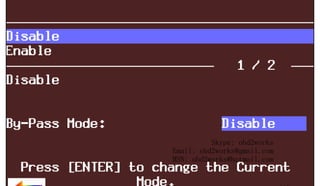
F6: Set Communication By-Pass Mode
When you select F6: Set Communication By-Pass Mode, the upcoming screen (Figure VIIA-10) offers
Disable and Enable options. By enabling the by-pass mode, the Tech 2 bypasses error handling and
allows the user to view data display information without being connected to a vehicle. Highlight the desired
setting using the up or down arrow keys, then press [ENTER] to change the current mode. The Tech 2 will
default to the Disable mode after it has been powered off.
Figure VIIA-10
Set Communication By-Pass Mode screen
Skype: obd2works
Email: obd2works@gmail.com
MSN: obd2works@hotmail.com
Tool Options continued on next page...
2005
Tech 2 User’s Guide
VII - 9
www.xcar360.com](https://image.slidesharecdn.com/gmtech2usermanual-131126203939-phpapp01/85/Gm-tech-2-user-manual-59-320.jpg)
![RETURN TO MAIN MENU
SECTION VIIA
TECH 2 MAIN MENU & LIVE PLOT
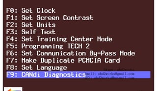
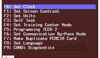
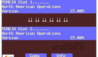
F7: Make Duplicate PCMCIA Card
After you select the F7: Make Duplicate PCMCIA Card option, which enables you to duplicate current
PCMCIA card data, the display will ask you to insert the destination card (the PCMCIA card that you want
to update) into the open PCMCIA card slot, then press [ENTER] to continue. The PCMCIA Card Duplicator
screen (Figure VIIA-11) will appear, showing the current version of both cards. The highlighted areas on
the screen represent the locations of the source and destination PCMCIA cards, and the arrows indicate
the direction of the data flow. Slot 1 is defined as the slot closest to the Tech 2 display. Use the Copy soft
key to initiate the duplication process.
If the card capacity is too small (less than 32 megabytes), a screen like the one shown in Figure VIIA-12
will appear. Insert a 32-megabyte PCMCIA card to resolve the problem.
com
s.
k
Figure VIIA-11
PCMCIA Card Duplicator screen displaying card data for both Tech 2 slots
wor
bd2
Figure VIIA-12
PCMCIA Card Duplicator screen displaying “Card Too Small” message
F8: Set Language
w.o
ww
The F8: Set Language option enables you to set your language preference.
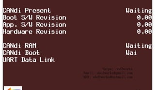
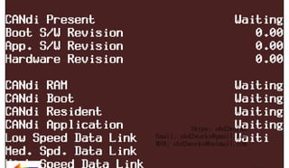
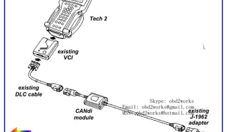
F9: CANdi Diagnostics
When you select F9: CANdi Diagnostics (a function limited to certain vehicles), the CANdi Diagnostics
screen (Figure VI-30) appears and you may perform a complete diagnosis of the CANdi module.
Refer to Section VI and Section VIID for more detail on CANdi diagnostics.
Skype: obd2works
Email: obd2works@gmail.com
MSN: obd2works@hotmail.com
2005
Tech 2 User’s Guide
VII - 10
www.xcar360.com](https://image.slidesharecdn.com/gmtech2usermanual-131126203939-phpapp01/85/Gm-tech-2-user-manual-60-320.jpg)
![RETURN TO MAIN MENU
SECTION VIIB
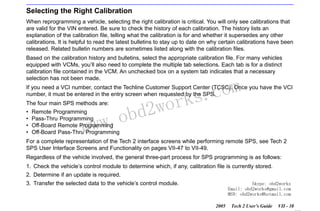
TIS SOFTWARE
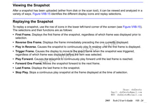
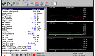
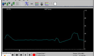
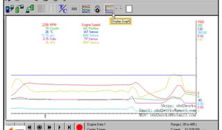
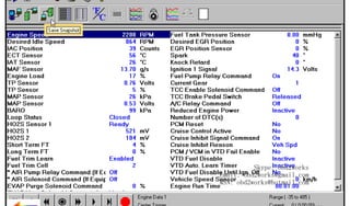
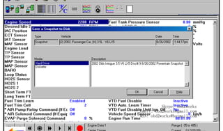
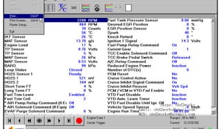
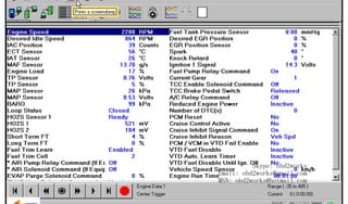
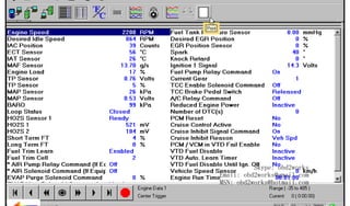
Trigger Type (F0 - F3 function keys) determines how the snapshot is triggered:
F0: Manual Trigger triggers a snapshot when you press the Trigger soft key.
F1: Any Code triggers a snapshot whenever any current trouble code is stored. This event occurs
when the first code is stored in the vehicle controller memory.
F2: Single Code triggers a snapshot when a user specified trouble code is stored.
F3: Automatic Trigger (chassis applications only) automatically triggers a snapshot.
Trigger Point (F4 - F6 function keys) is the exact point at which the trouble code (fault) or manual
trigger occurs within the snapshot period. It helps to know the trigger point when you are looking for
changes in data parameters. Trigger point may be set for:
com
s.
k
F4: Beginning causes the Tech 2 to start recording information from the trigger point until
snapshot storage is full. This choice is useful if the fault is predictable.
F5: Center is the most commonly used trigger point because it stores information leading up to
and following the trigger point. This function allows comparison of events before, during, and
after a fault.
F6: End sets the trigger point at the end of the snapshot recording and therefore shows only
information leading up to and including the fault.
w.o
ww
wor
bd2
6. Press the Record Snapshot soft key. The Tech 2 screen will display the flashing message “standby.”
• When the fault occurs, press the Trigger soft key.
• The Tech 2 will display the message “triggered.”
• Allow the scan tool to record a sufficient amount of data, then press [EXIT] to store the snapshot data.
• Press the Continue soft key when the snapshot trigger type screen is displayed.
7. Exit to the Main Menu, then power down and disconnect the Tech 2 from the vehicle.
Skype: obd2works
Email: obd2works@gmail.com
MSN: obd2works@hotmail.com
2005
Tech 2 User’s Guide
VII - 22
www.xcar360.com](https://image.slidesharecdn.com/gmtech2usermanual-131126203939-phpapp01/85/Gm-tech-2-user-manual-72-320.jpg)

![RETURN TO MAIN MENU
SECTION VIIC
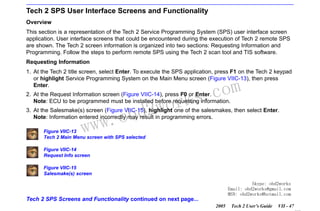
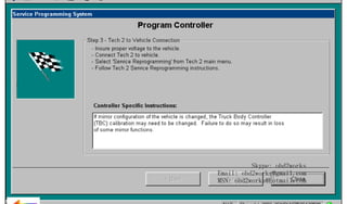
SERVICE PROGRAMMING SYSTEM
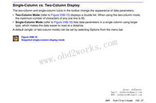
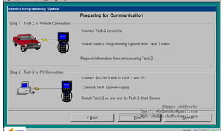
Performing Remote SPS
NOTICE
ECU to be programmed must be installed in the vehicle before beginning this process. Make sure the
battery is fully charged.
Perform remote SPS using TIS as follows:
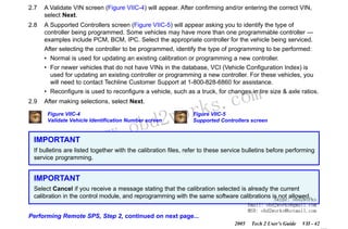
STEP 1: Obtain Vehicle Information (Request Info) from new ECU or an ECU to be programmed.
1.1
1.2
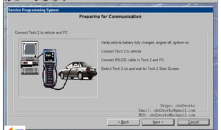
With the Tech 2 and vehicle both off, connect the Tech 2 to the vehicle DLC (Figure III-23).
Power on the Tech 2. At the Tech 2 title screen, press [ENTER].
1.3
Turn the vehicle ignition to the on position (engine off).
1.4
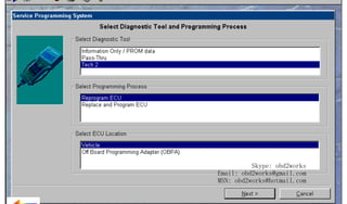
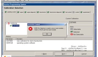
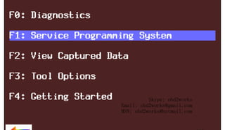
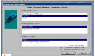
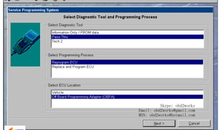
At the Tech 2 Main Menu, select Service Programming System (Figure VIIC-13).
1.5
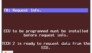
Select “Request Info” on the Tech 2 (Figure VIIC-14).
IMPORTANT
w.o
ww
wor
bd2
com
s.
k
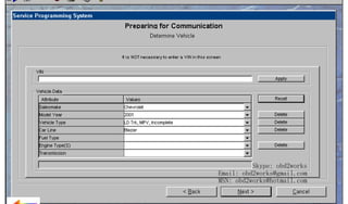
If a VIN was previously stored in the Tech 2, press Request New Info (soft key), and follow the onscreen directions.
1.6
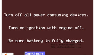
Follow the on-screen instructions. After the vehicle description is entered, turn off all power
consuming devices, then press Continue (soft key).
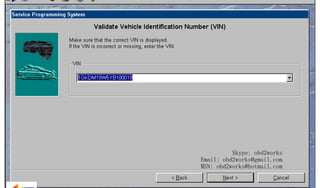
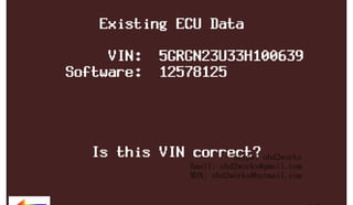
1.7
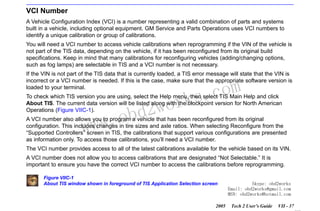
The Tech 2 reads the VIN, then displays the VIN and calibrations. The Tech 2 will ask “Is this VIN
correct?” Select Yes. (If the answer is No, write down the VIN number.)
Skype: obd2works
Email: obd2works@gmail.com
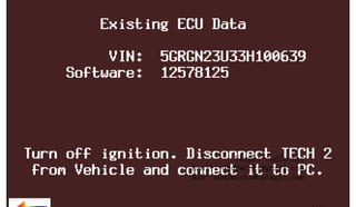
When finished, press [EXIT], power down, and disconnect the Tech 2 from MSN: vehicle. Turn the
the obd2works@hotmail.com
vehicle ignition off.
1.8
2005
Tech 2 User’s Guide
VII - 40
www.xcar360.com](https://image.slidesharecdn.com/gmtech2usermanual-131126203939-phpapp01/85/Gm-tech-2-user-manual-90-320.jpg)
![RETURN TO MAIN MENU
SECTION VIIC
SERVICE PROGRAMMING SYSTEM
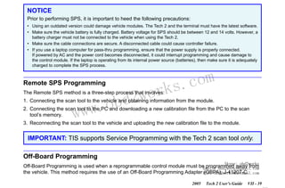
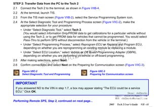
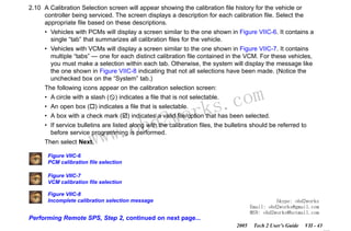
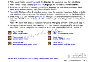
STEP 3: Transfer Data from the Tech 2 to the Control Module
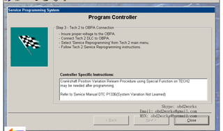
3.1
With the Tech 2 and vehicle both off, connect the Tech 2 to the vehicle DLC (Figure III-23).
3.2
Power on the Tech 2. At the Tech 2 title screen, press [ENTER].
3.3
Turn the vehicle ignition to the “on” position (engine off).
3.4
At the Tech 2 Main Menu, select Service Programming System (Figure VIIC-13).
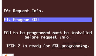
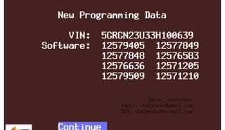
3.5
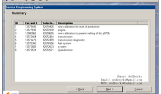
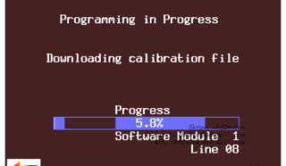
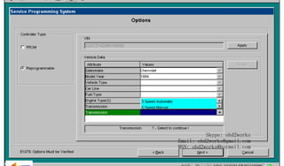
Select "F1: Program ECU" on the Tech 2 (Figure VIIC-22). The Tech 2 will display the new
programming data — VIN and software numbers (Figure VIIC-23). Verify, then select the soft key
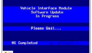
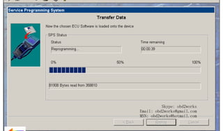
Continue. The Tech 2 will display the "Programming in Progress - Downloading calibration file"
screen (Figure VIIC-24).
3.6
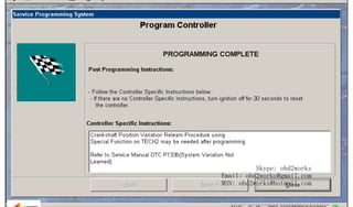
When the transfer is complete, the Tech 2 will display the message “Programming Was Successful.”
Press the Continue soft key to exit the program. Turn the vehicle ignition off first, then turn the Tech
2 off and disconnect it from the vehicle.
wor
bd2
com
s.
k
Be sure to verify successful reprogramming. Refer to the recommendations on the next page.
w.o
ww
Skype: obd2works
Email: obd2works@gmail.com
MSN: obd2works@hotmail.com
2005
Tech 2 User’s Guide
VII - 45
www.xcar360.com](https://image.slidesharecdn.com/gmtech2usermanual-131126203939-phpapp01/85/Gm-tech-2-user-manual-95-320.jpg)
![RETURN TO MAIN MENU
SECTION VIIC
SERVICE PROGRAMMING SYSTEM
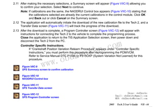
NOTICE
To help avoid possible controller failure, make sure all cable connections are secure.
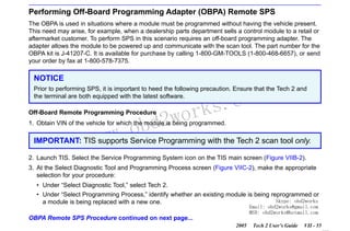
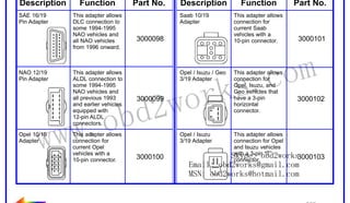
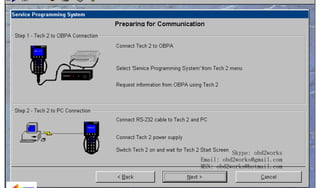
16. Reconnect the Tech 2 to the OBPA. Enter the Tech 2 “Service Programming” function and download
the calibration to the module by selecting the Program ECU function (F1). At the New Programming
Data screen (Figure VIIC-23), press the Continue soft key. Follow the Tech 2 on-screen instructions,
then press the Continue soft key.
17. When programming is complete, press [EXIT] on the Tech 2, power off the OBPA, then power off the
Tech 2.
IMPORTANT
wor
bd2
com
s.
k
Wait 30 seconds after OBPA is shut off before disconnecting the control module in order to allow the
controller to reset.
w.o
ww
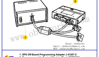
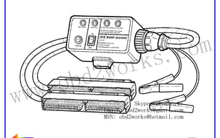
Figure VIIC-37
OBPA connected to control module
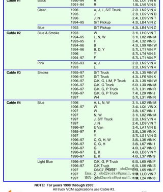
Figure VIIC-38
Table showing OBPA adapter selection information
Skype: obd2works
Email: obd2works@gmail.com
MSN: obd2works@hotmail.com
2005
Tech 2 User’s Guide
VII - 58
www.xcar360.com](https://image.slidesharecdn.com/gmtech2usermanual-131126203939-phpapp01/85/Gm-tech-2-user-manual-108-320.jpg)
![RETURN TO MAIN MENU
1
4
wor
d2
ob
3
ww.
w
om
s.c
k
2
Skype: obd2works
Email: obd2works@gmail.com
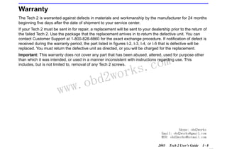
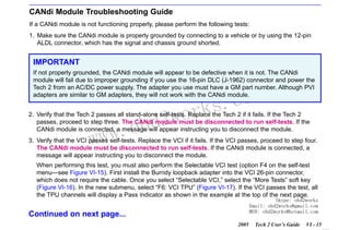
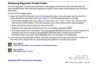
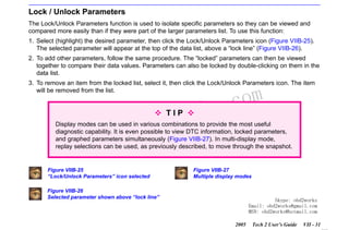
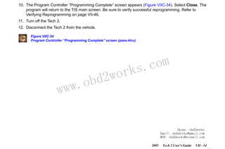
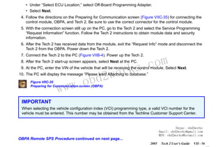
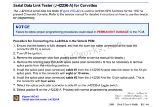
1. Highlighted (selected) area
2. Bottom [ENTER] key MSN: obd2works@hotmail.com
3. Down arrow (used to move highlighted
area downward line by line)
4. Top [ENTER] key
www.xcar360.com](https://image.slidesharecdn.com/gmtech2usermanual-131126203939-phpapp01/85/Gm-tech-2-user-manual-146-320.jpg)

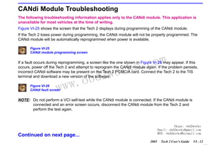
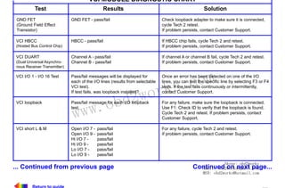
![RETURN TO MAIN MENU
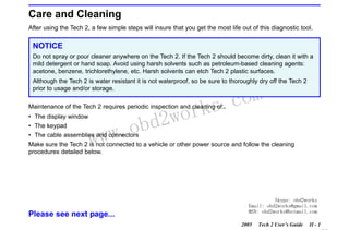
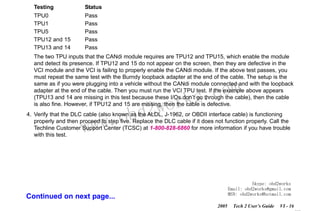
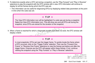
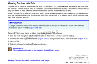
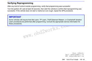
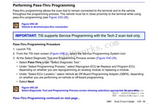
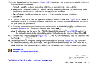
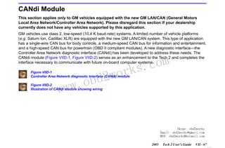
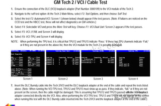
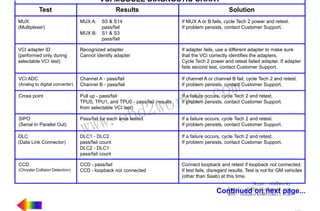
PCB DIAGNOSTIC CHART
Test
Results
Solution
RAM/ROM
0123-
Pass
ROM read fail
RAM read fail
RAM write and read do not compare.
Record type of failure.
Cycle Tech 2 power (press [PWR]) and retest.
If problem persists, contact Customer Support.
RS-485 loopback
Pass
Fail - Loopback may not be connected.
Check loopback connection.
If problem persists, contact Customer Support.
RS-232 loopback
Pass
Fail - Loopback may not be connected.
Check loopback connection.
If problem persists, contact Customer Support.
Keypad
Test successful
Keypad failed
Exiting the test before all keys are pressed
results in a failed keypad test.
Cycle Tech 2 power and retest.
If problem persists, contact Customer Support.
PCMCIA
(Tests both card slots)
Card detected
Card not present
Fail
Display controller
(Contrast and characters)
User determines if display is correct.
If the display shows a noticeable failure during tests,
contact Customer Support.
Sound transducer
User determines if sound transducer is
working.
If no sound is emitted by repeatedly selecting Automated Test or Sound On, contact Customer Support.
Real-time clock
Time is displayed correctly.
Invalid values are displayed for date, year,
hour, minute, or second.
Reset clock. Cycle Tech 2 power and retest. If time is
not retained, contact Customer Support.
w.o
ww
wor
bd2
com
s.
k
Check that card is inserted properly.
Cycle Tech 2 power and retest.
If problem persists, contact Customer Support.
Skype: obd2works
Email: obd2works@gmail.com
MSN: obd2works@hotmail.com
www.xcar360.com](https://image.slidesharecdn.com/gmtech2usermanual-131126203939-phpapp01/85/Gm-tech-2-user-manual-171-320.jpg)


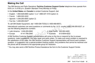
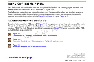
The Tech 2 User's Guide provides comprehensive information on the Tech 2 scan tool, including its operation, care, and troubleshooting. It details the procedure for customer support, warranty information, and licensing agreements, emphasizing the importance of proper usage and maintenance. The guide also includes safety warnings, operational guidelines, and technical specifications for effective diagnosis and repair of automotive systems.


