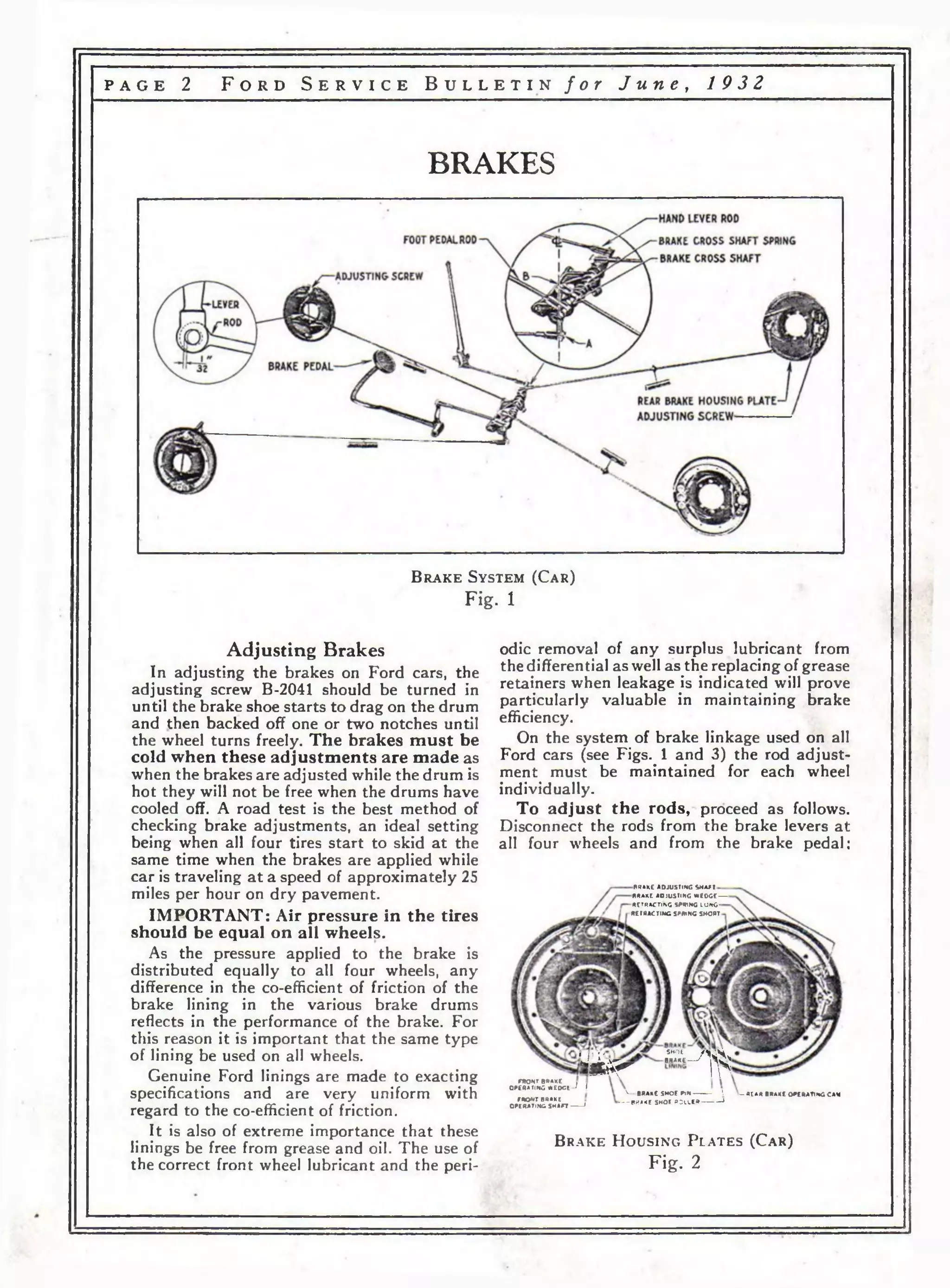
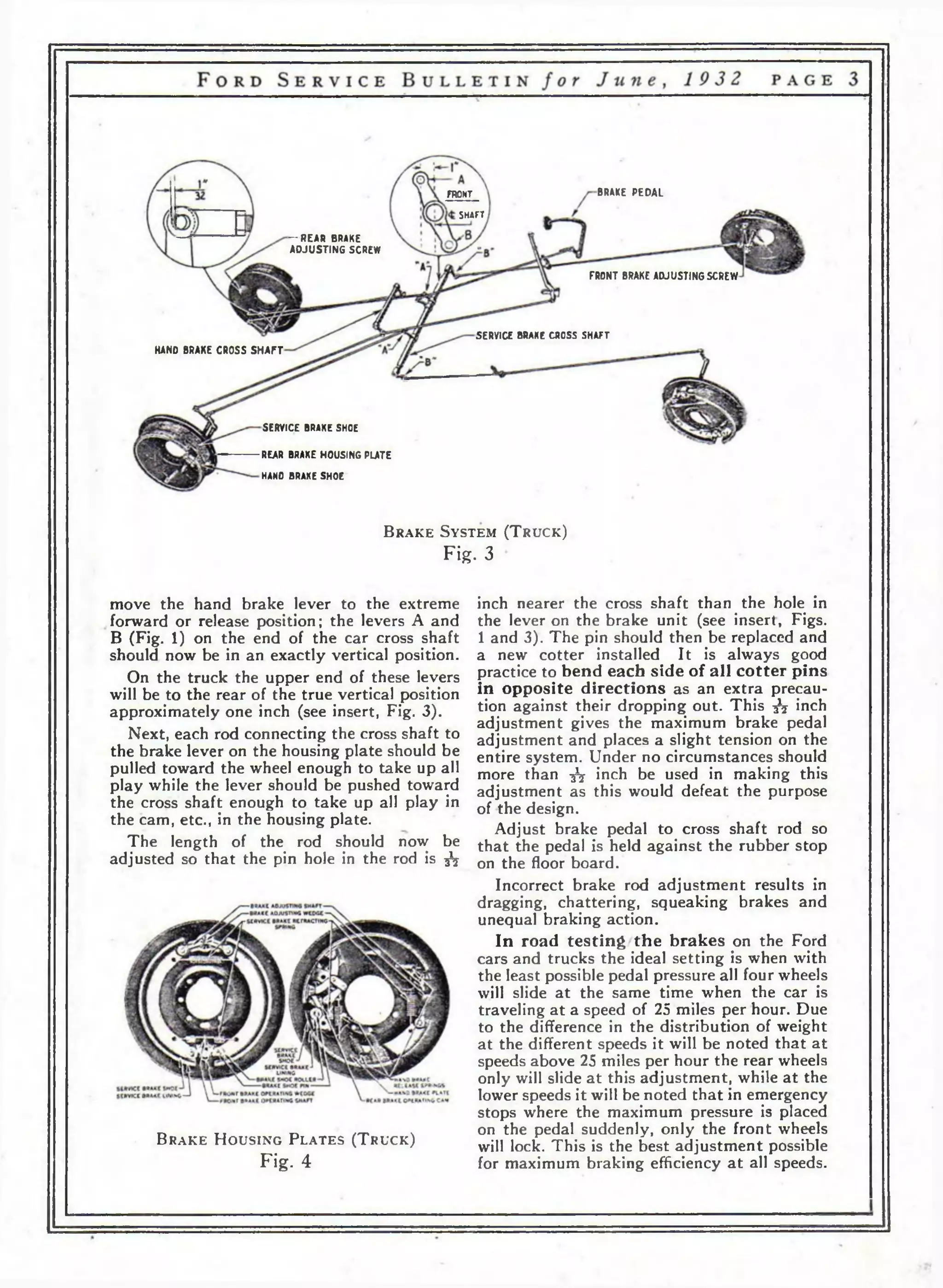
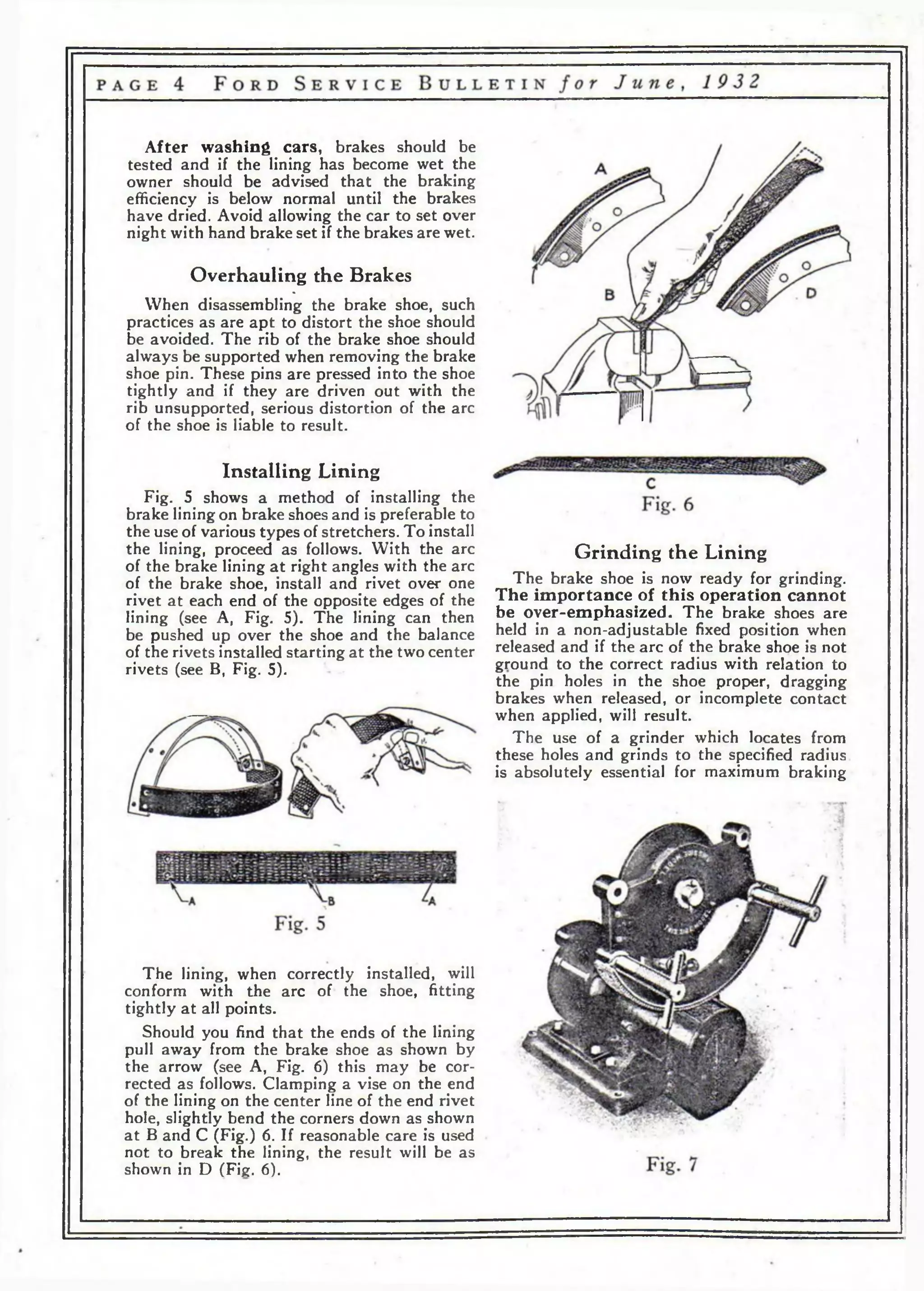
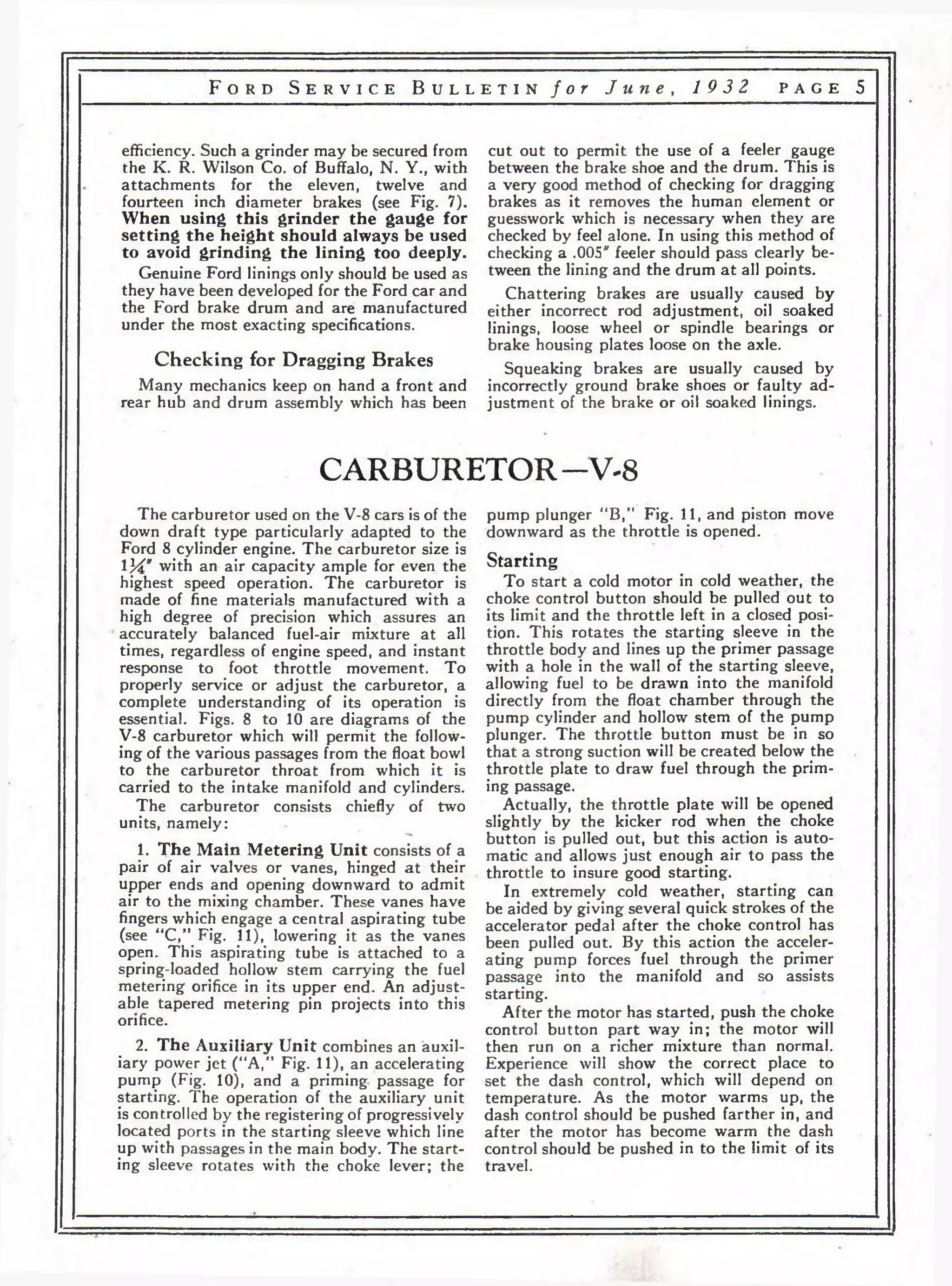
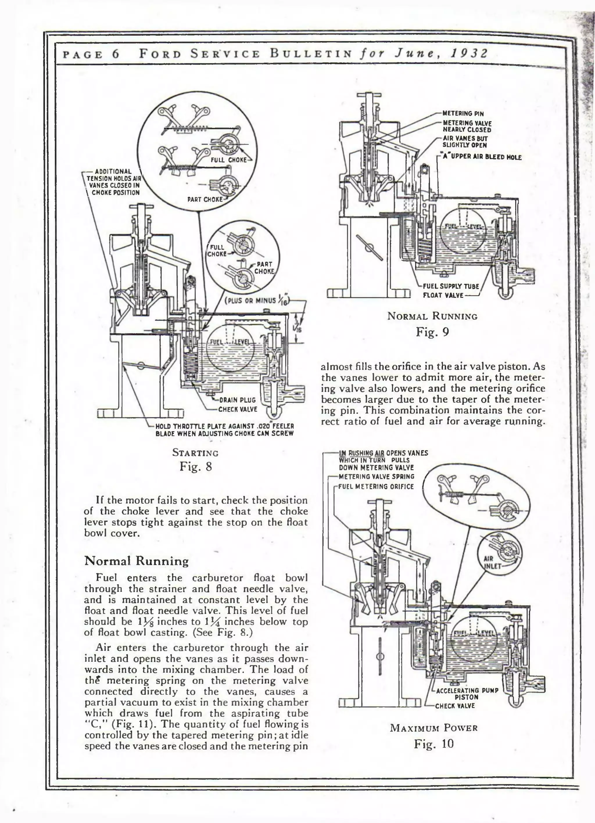
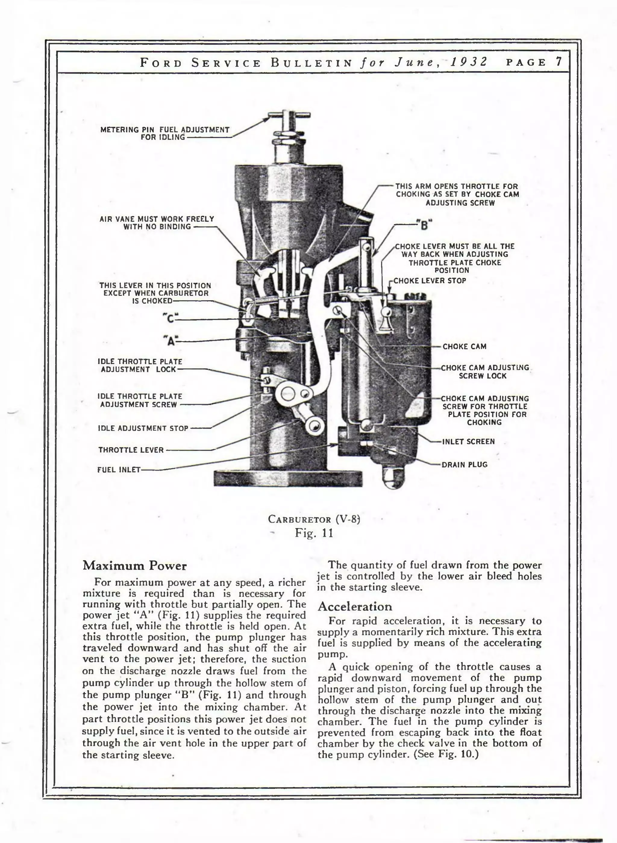
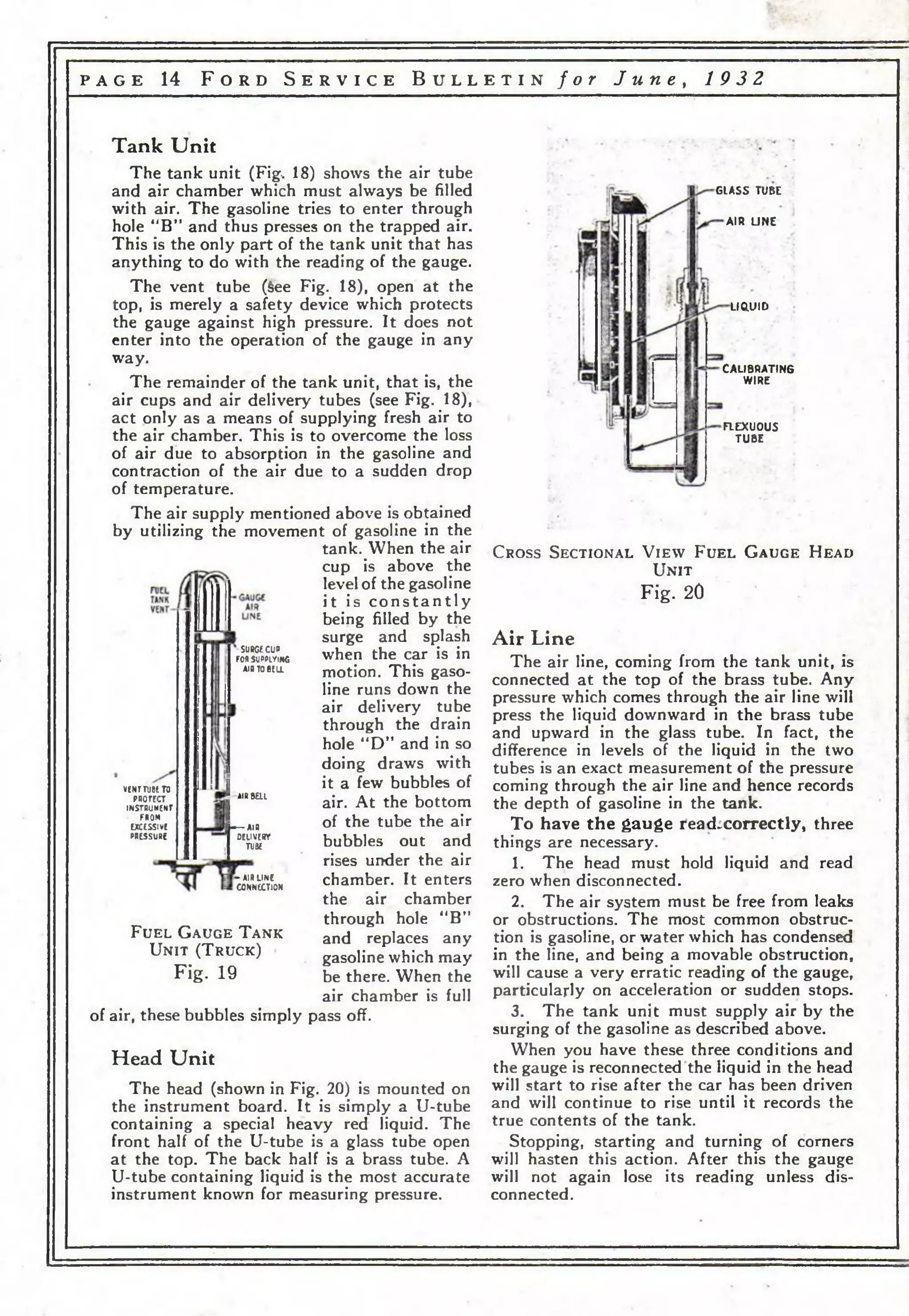
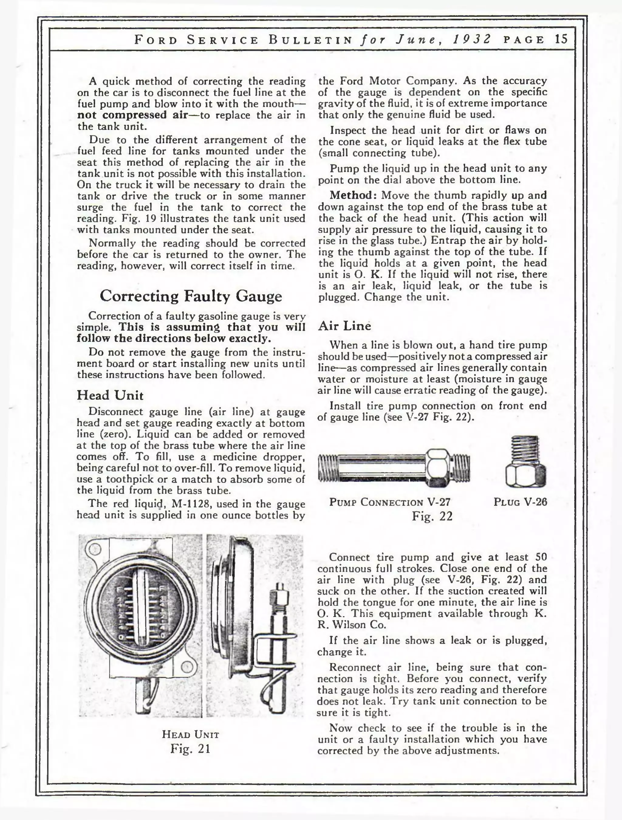
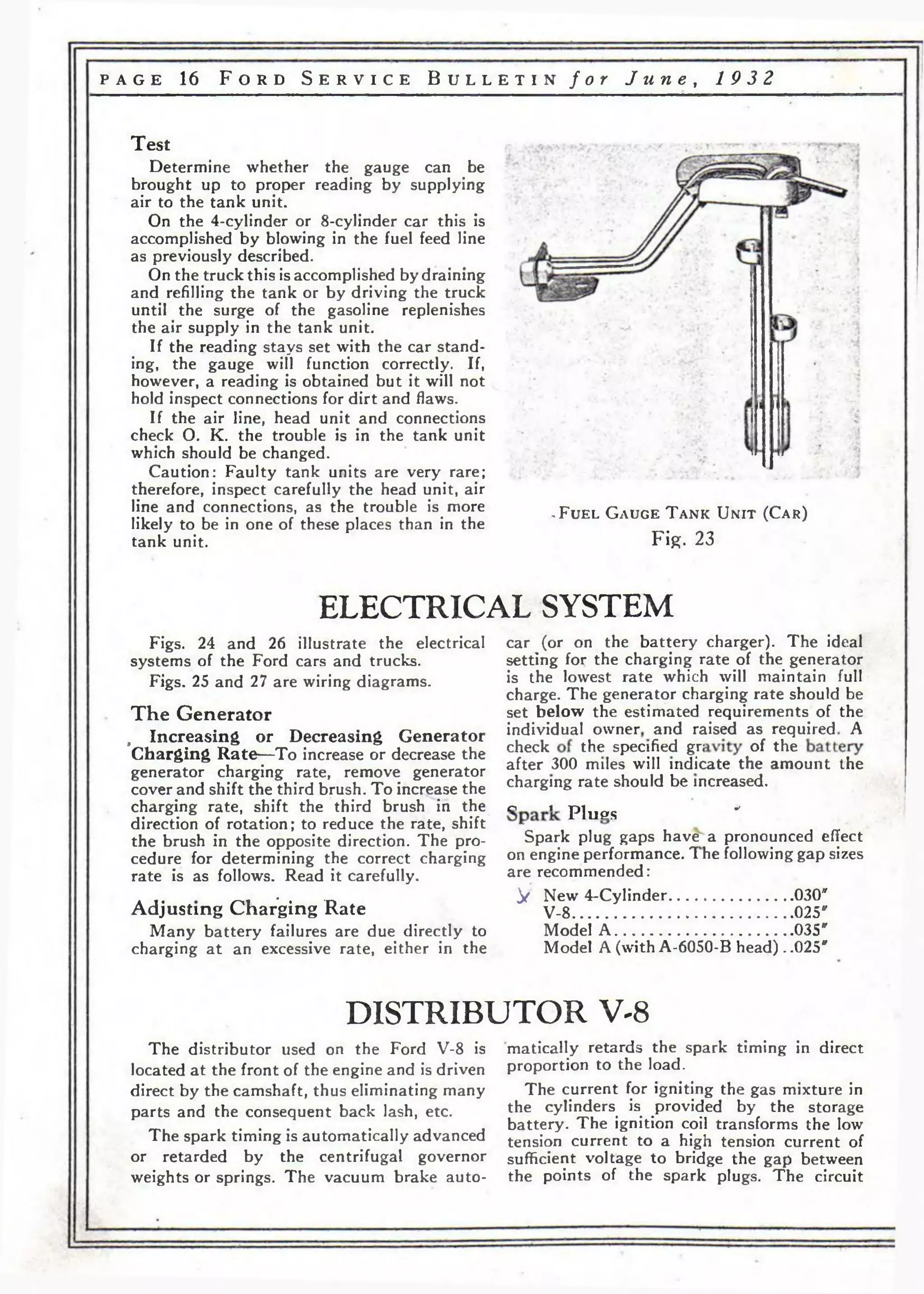
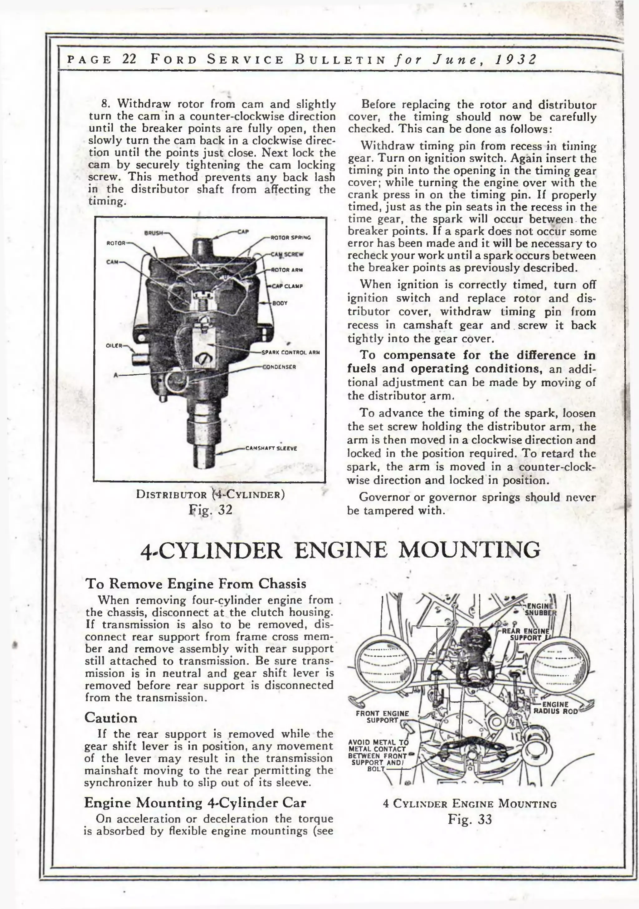
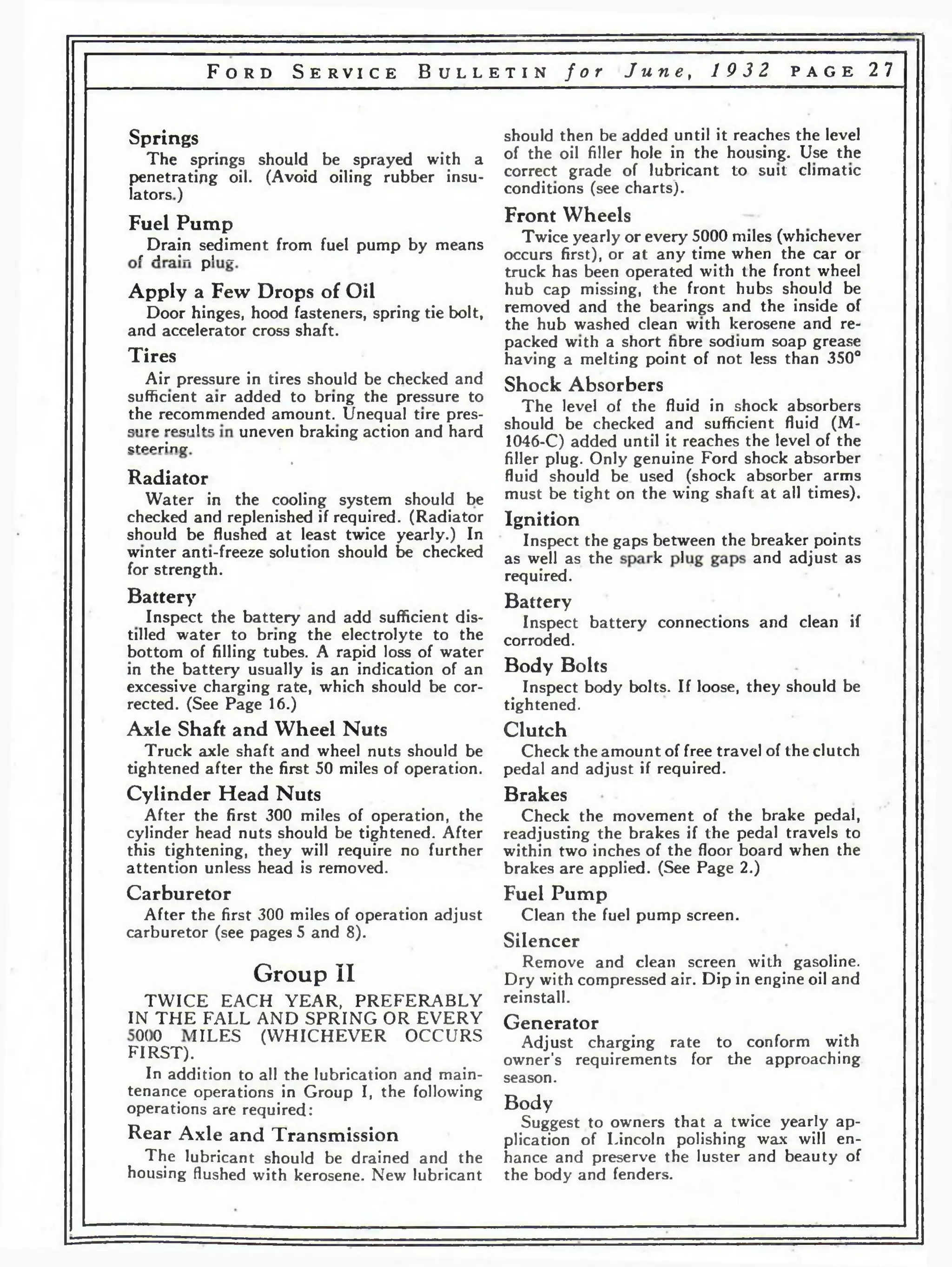
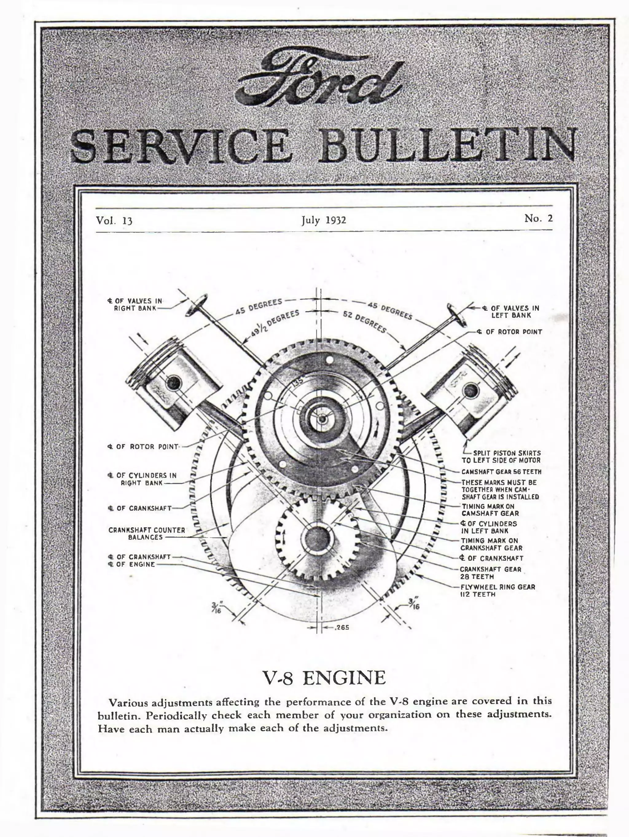
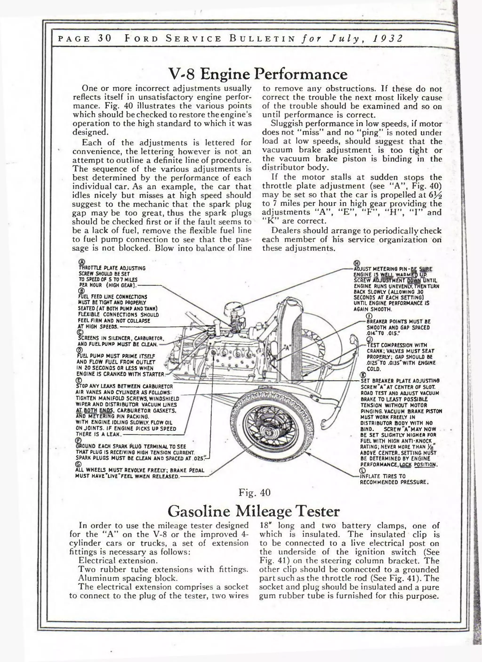
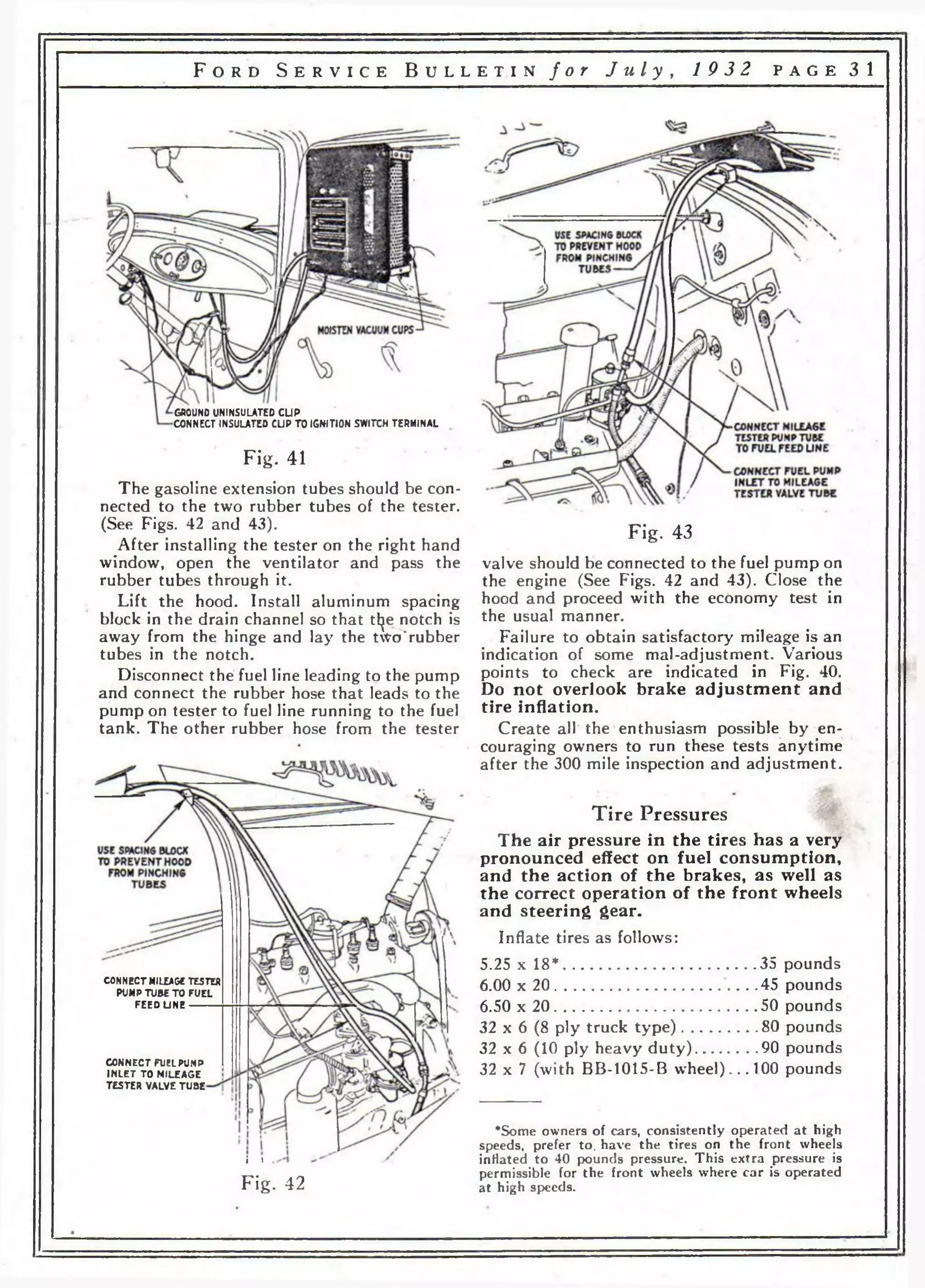
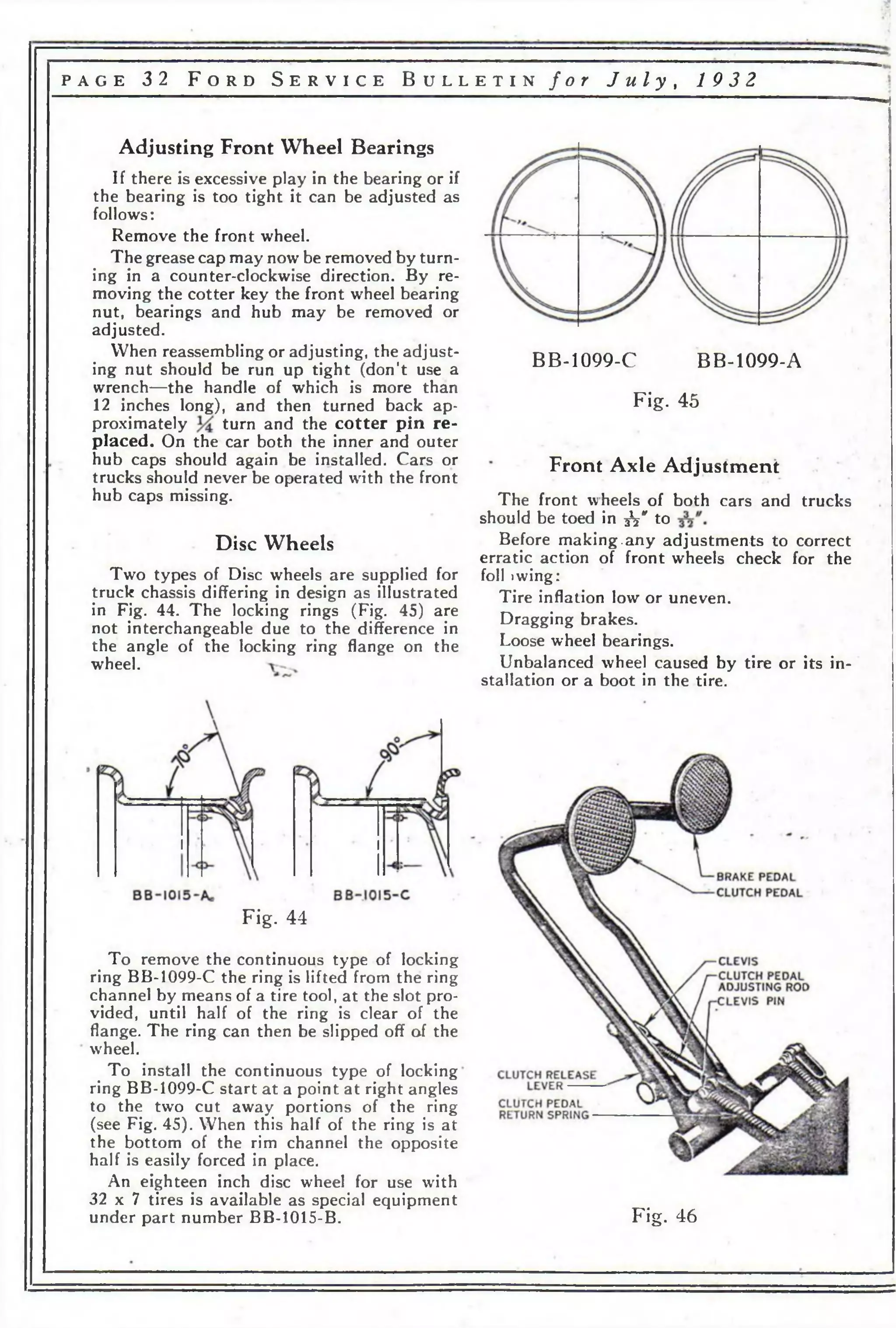
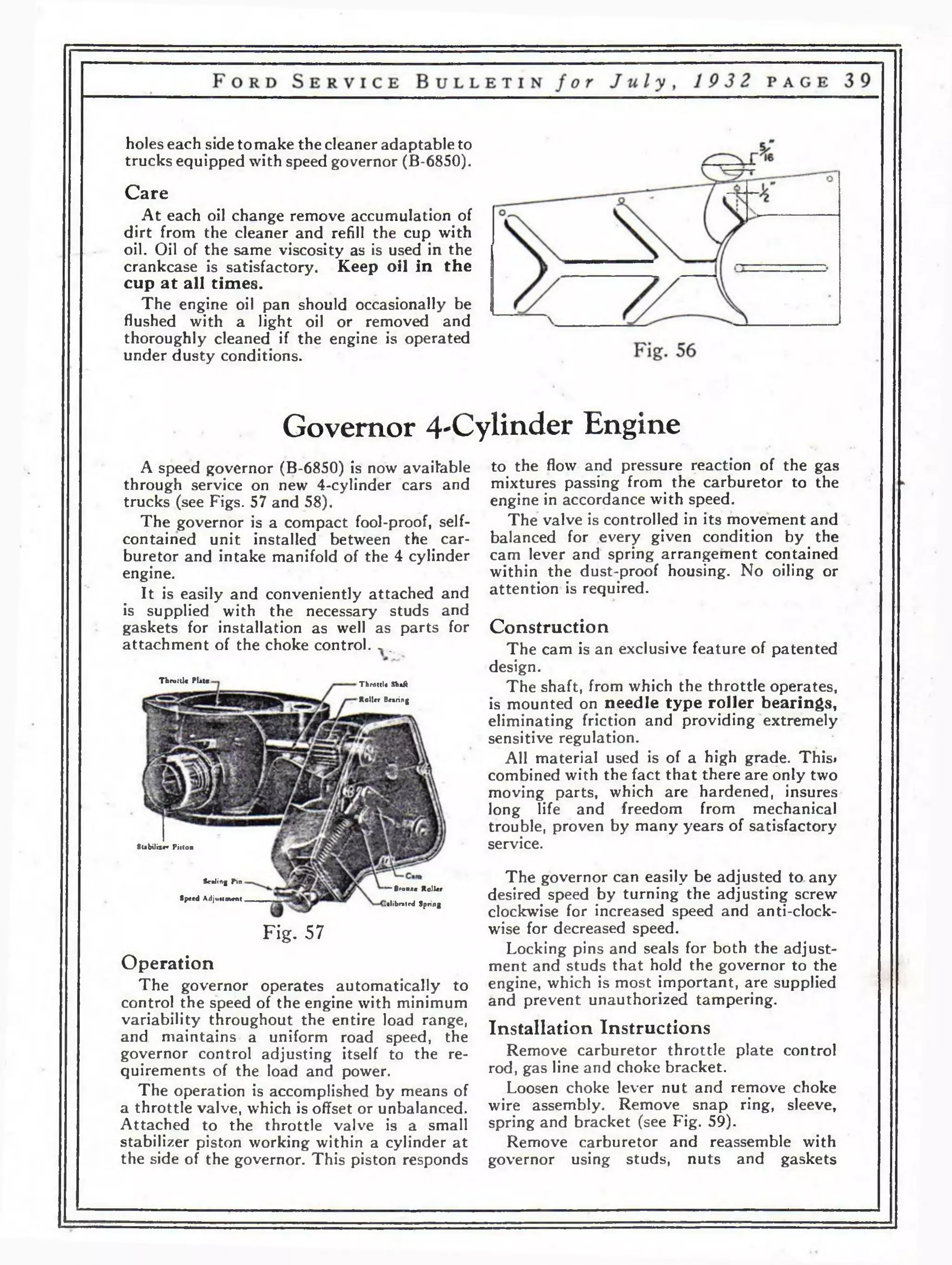
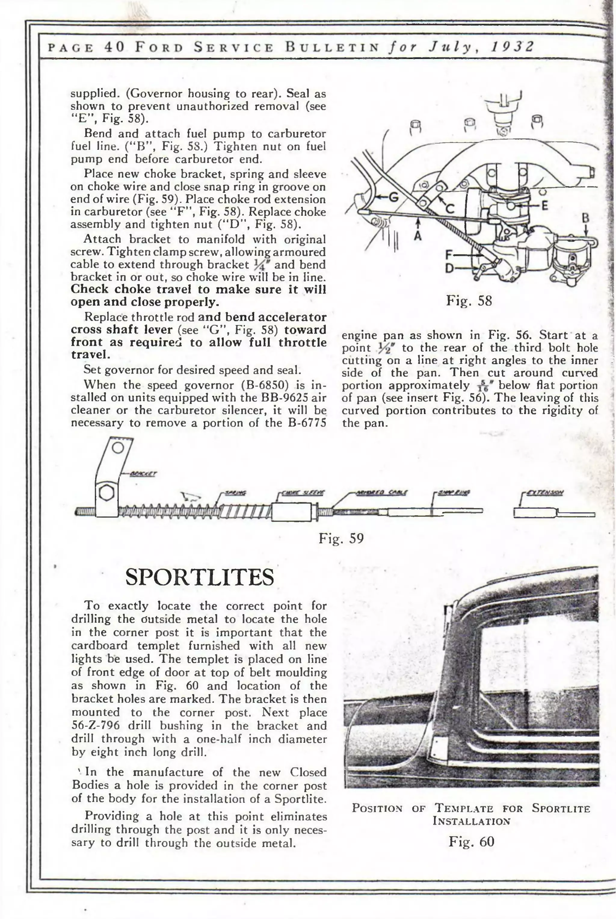
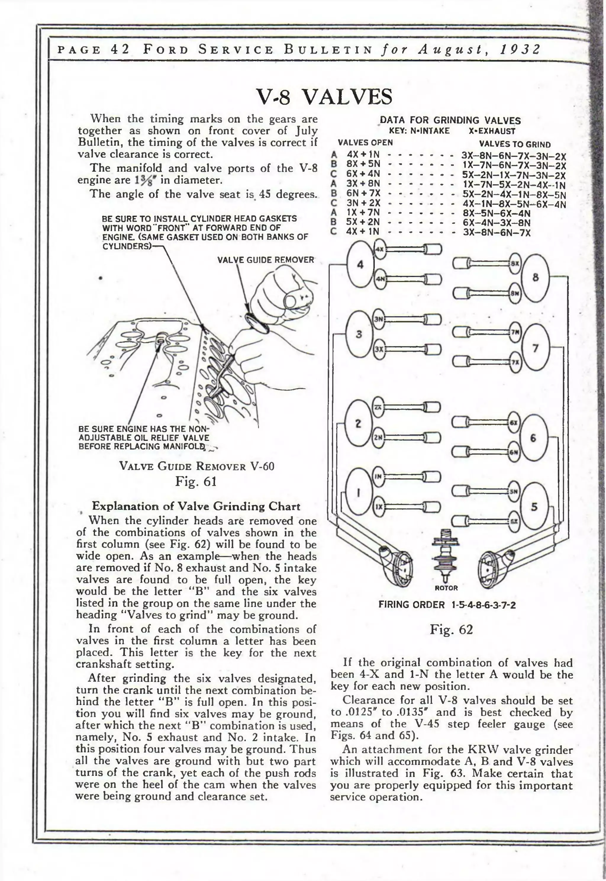
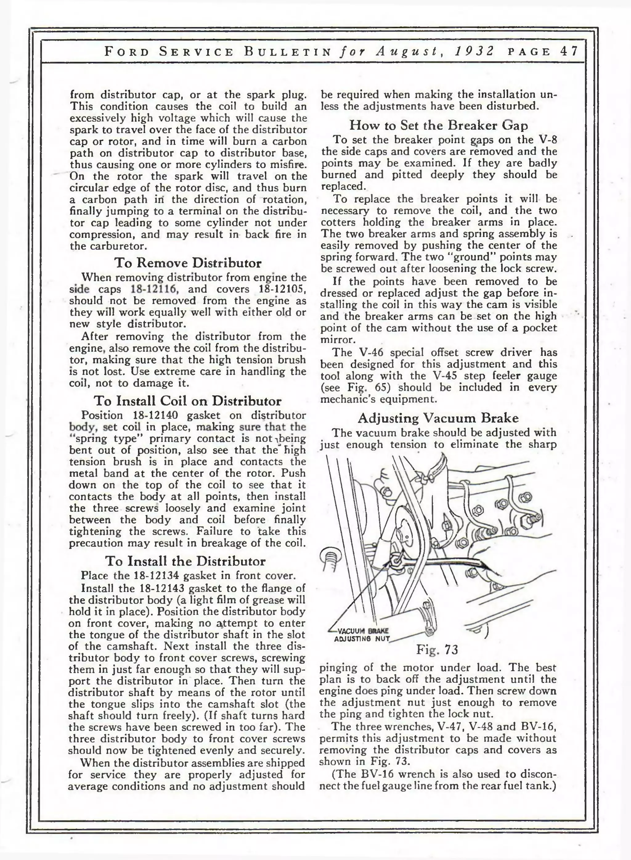
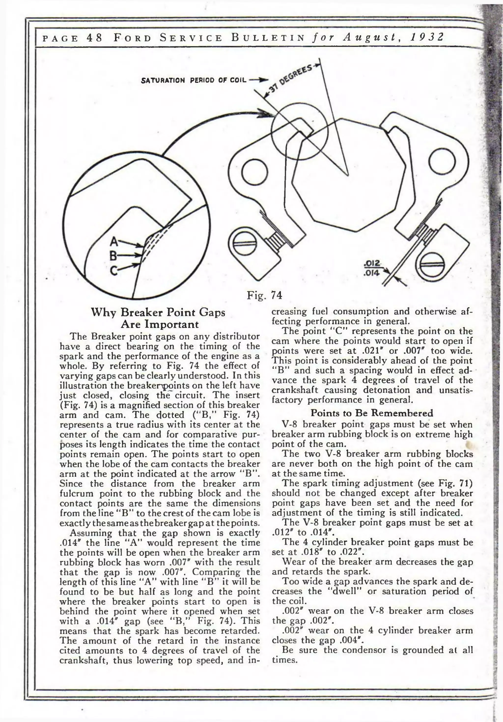
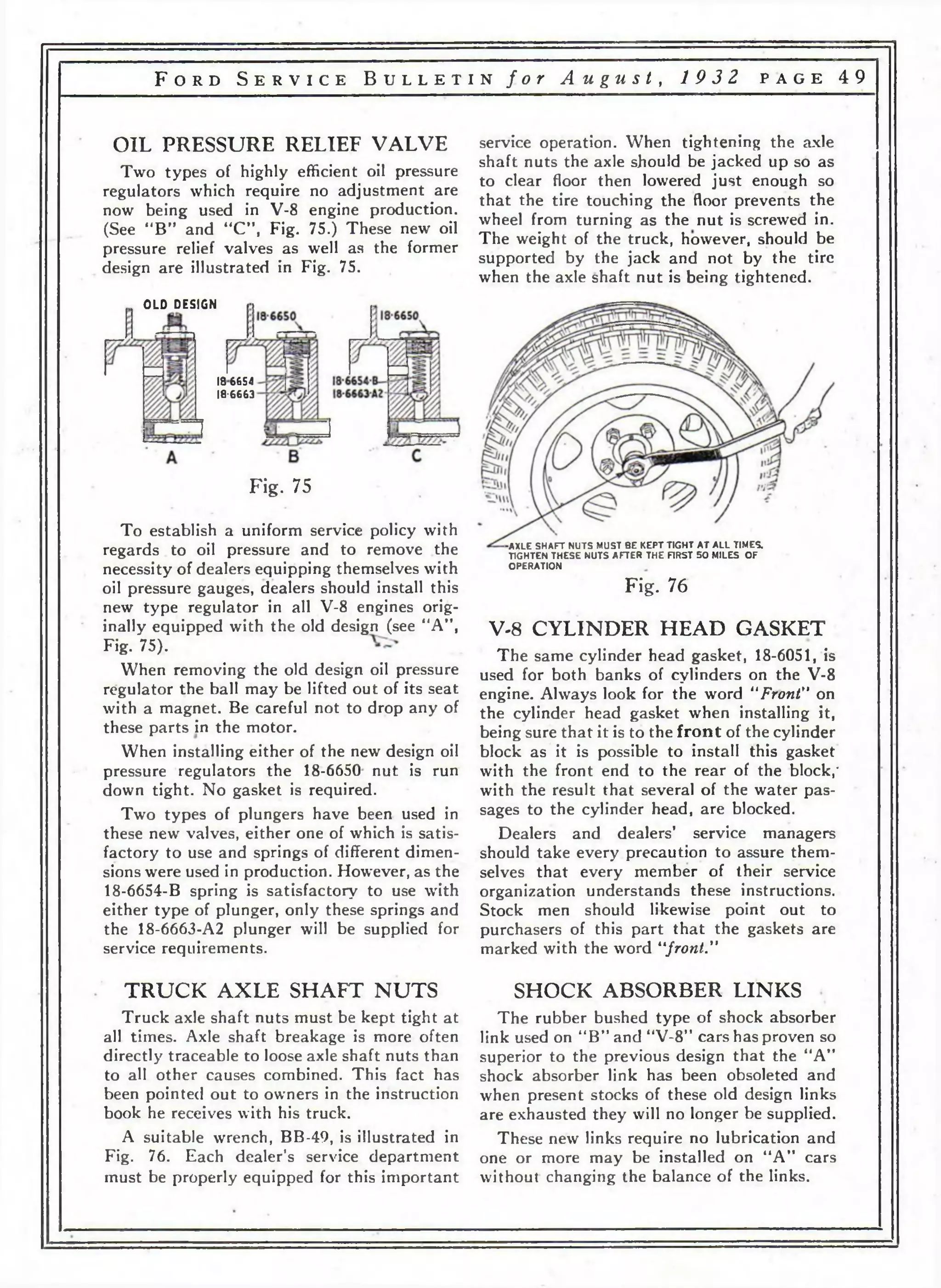
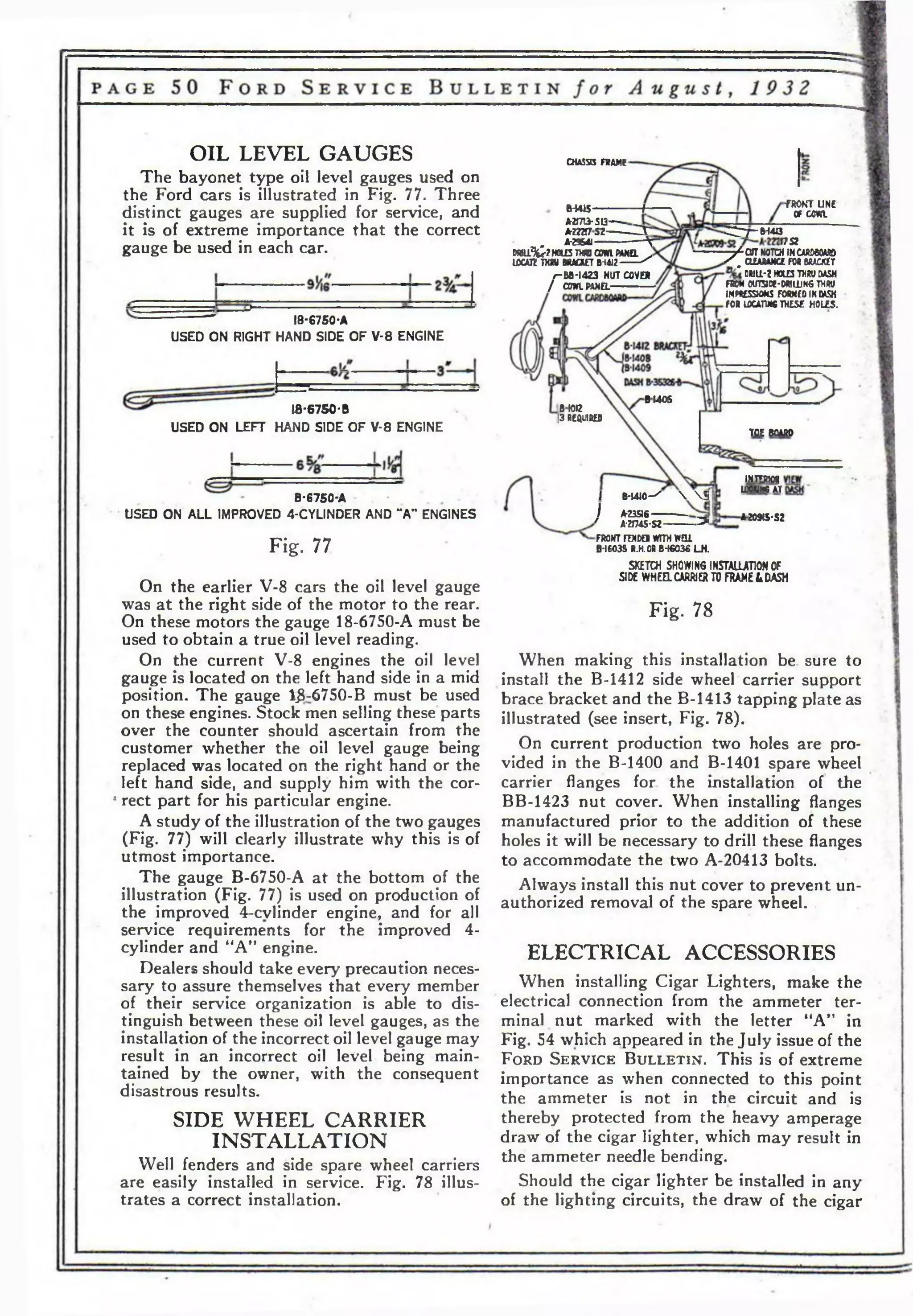
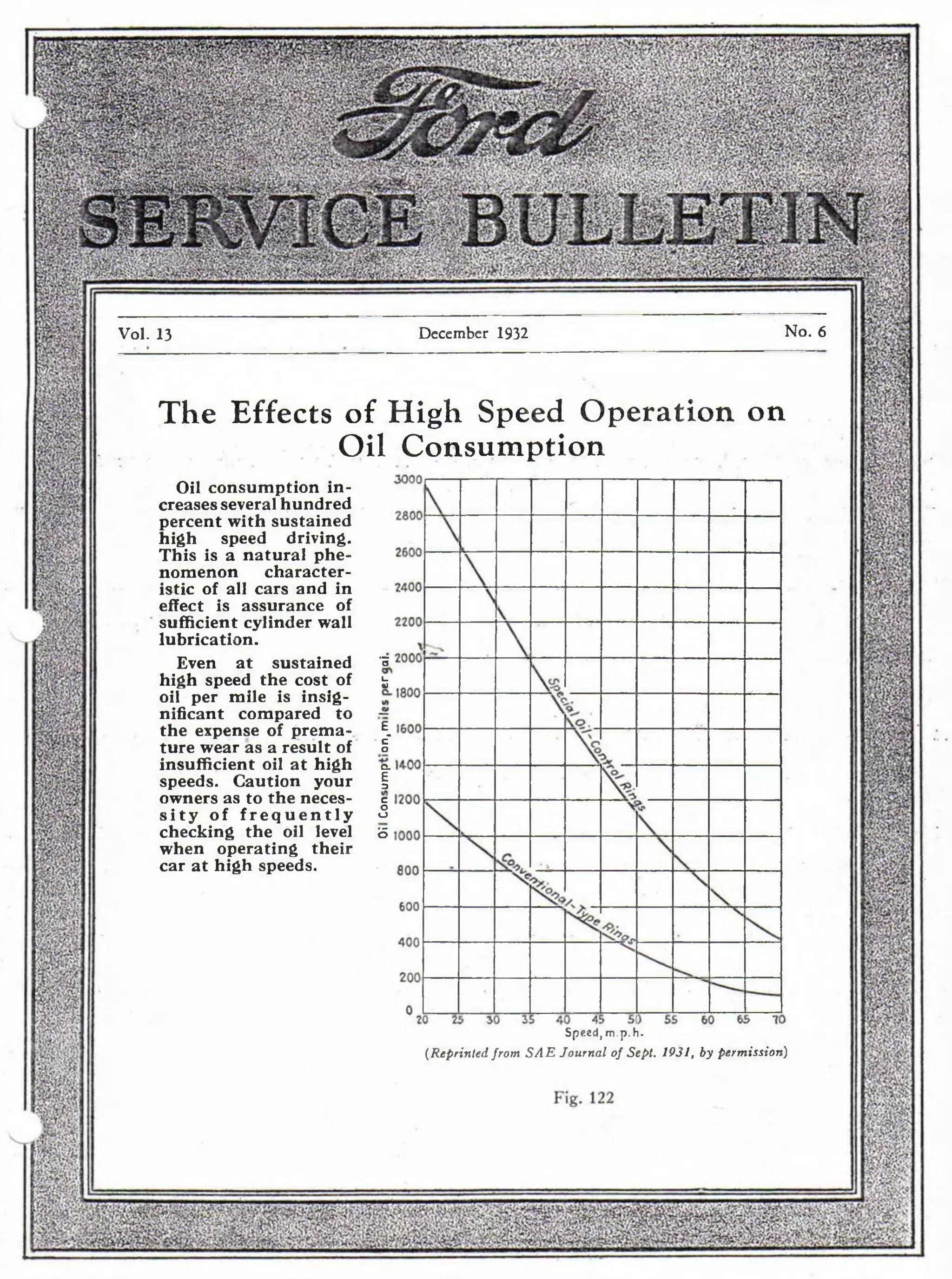
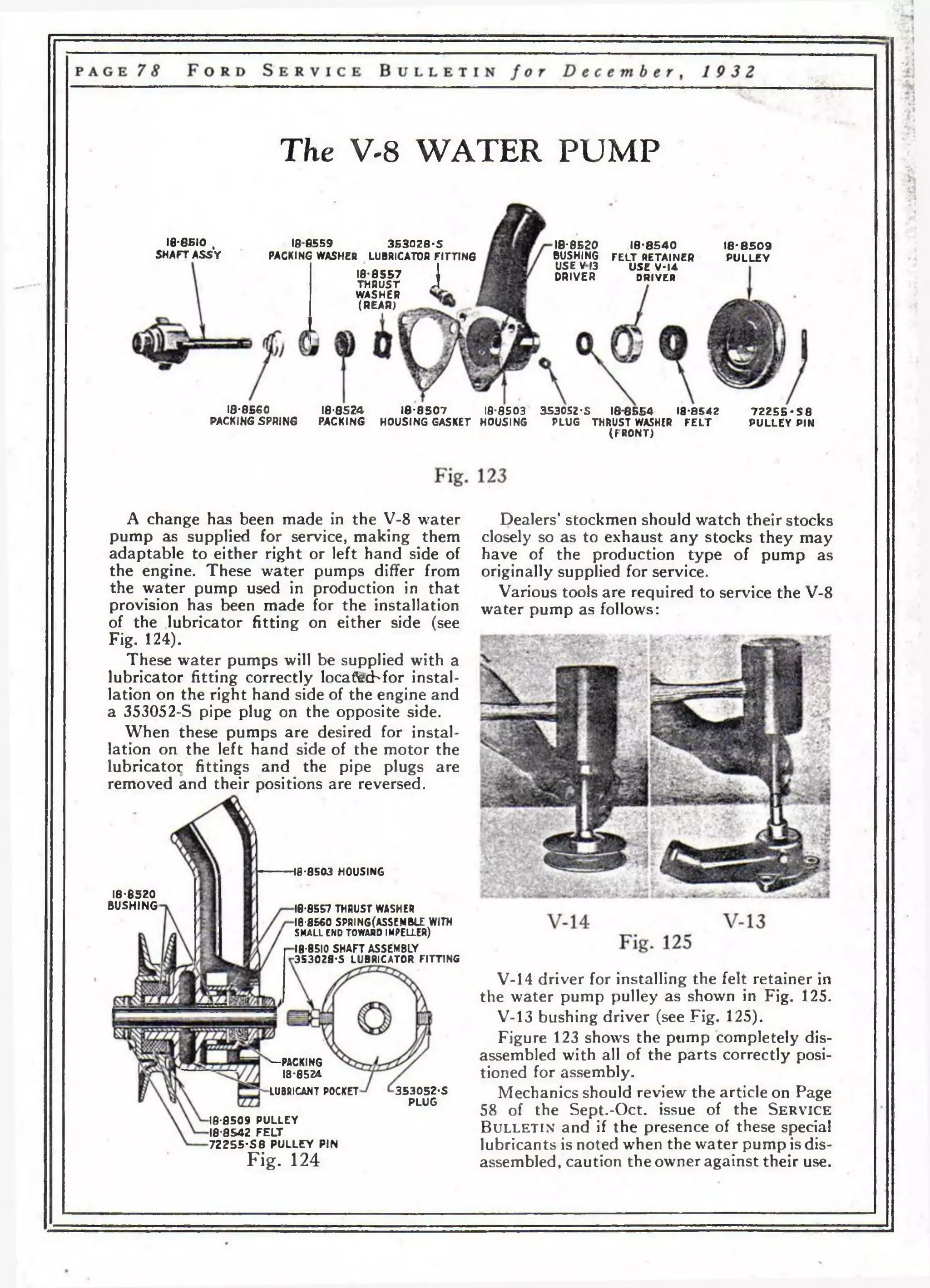
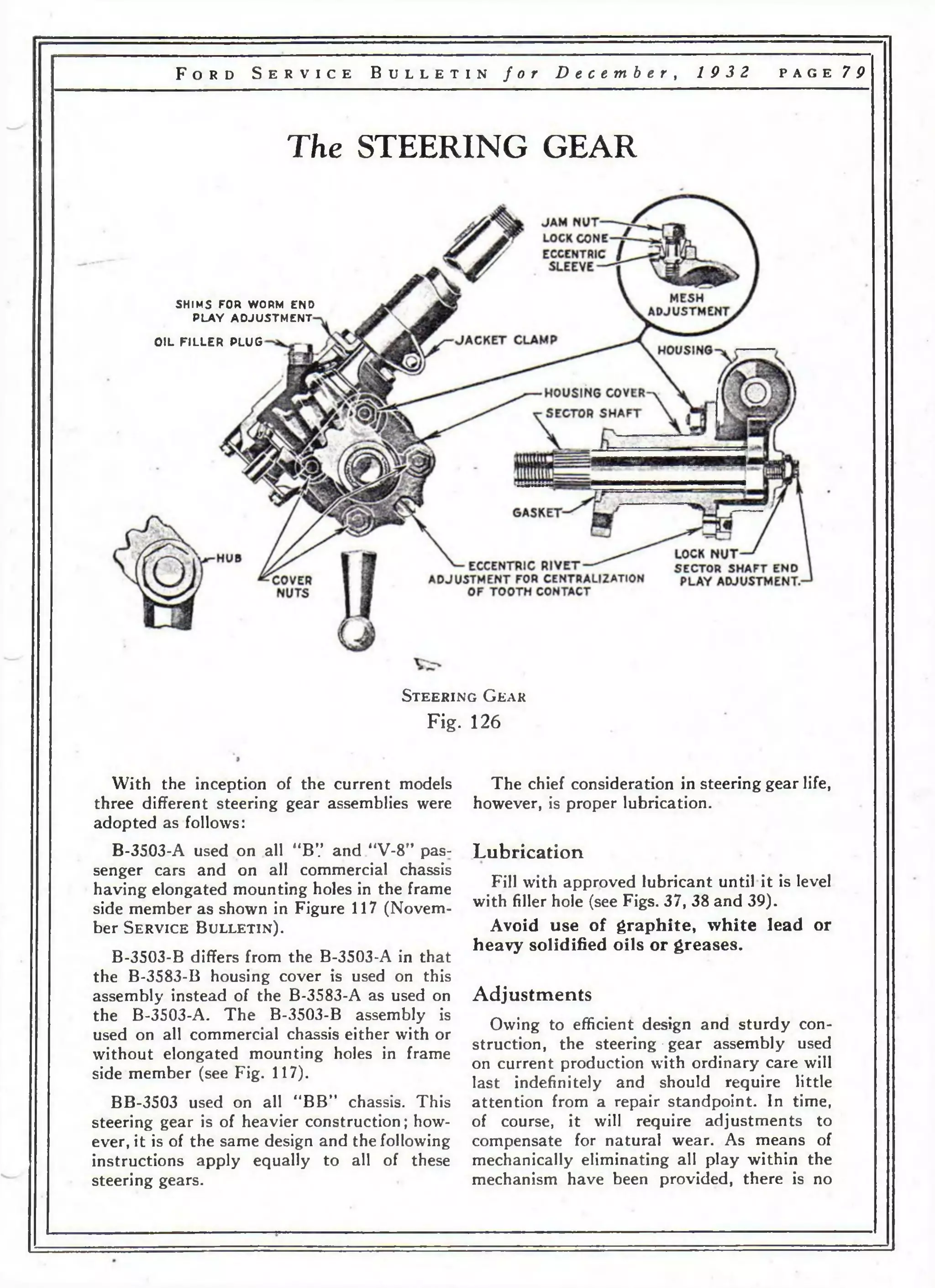
This document provides instructions for servicing Ford vehicles, including the V8 engine and 4-cylinder models from June 1932. It details procedures for adjusting brakes, overhauling brake shoes, installing brake linings, and checking for dragging brakes. It also provides an overview of the carburetor used for the V8 engine. The instructions emphasize properly adjusting brake rods and linkages, grinding brake shoe arcs to the correct radius, and only using genuine Ford brake linings.

![p a g e 10 F o r d S e r v i c e B u l l e t i n f o r J u n e , 1 9 3 2
Tires soft—under inflated tires are responsible
for more complaints of excessive fuel
consumption than any other cause. Inflate all
tires to the recommended pressure.
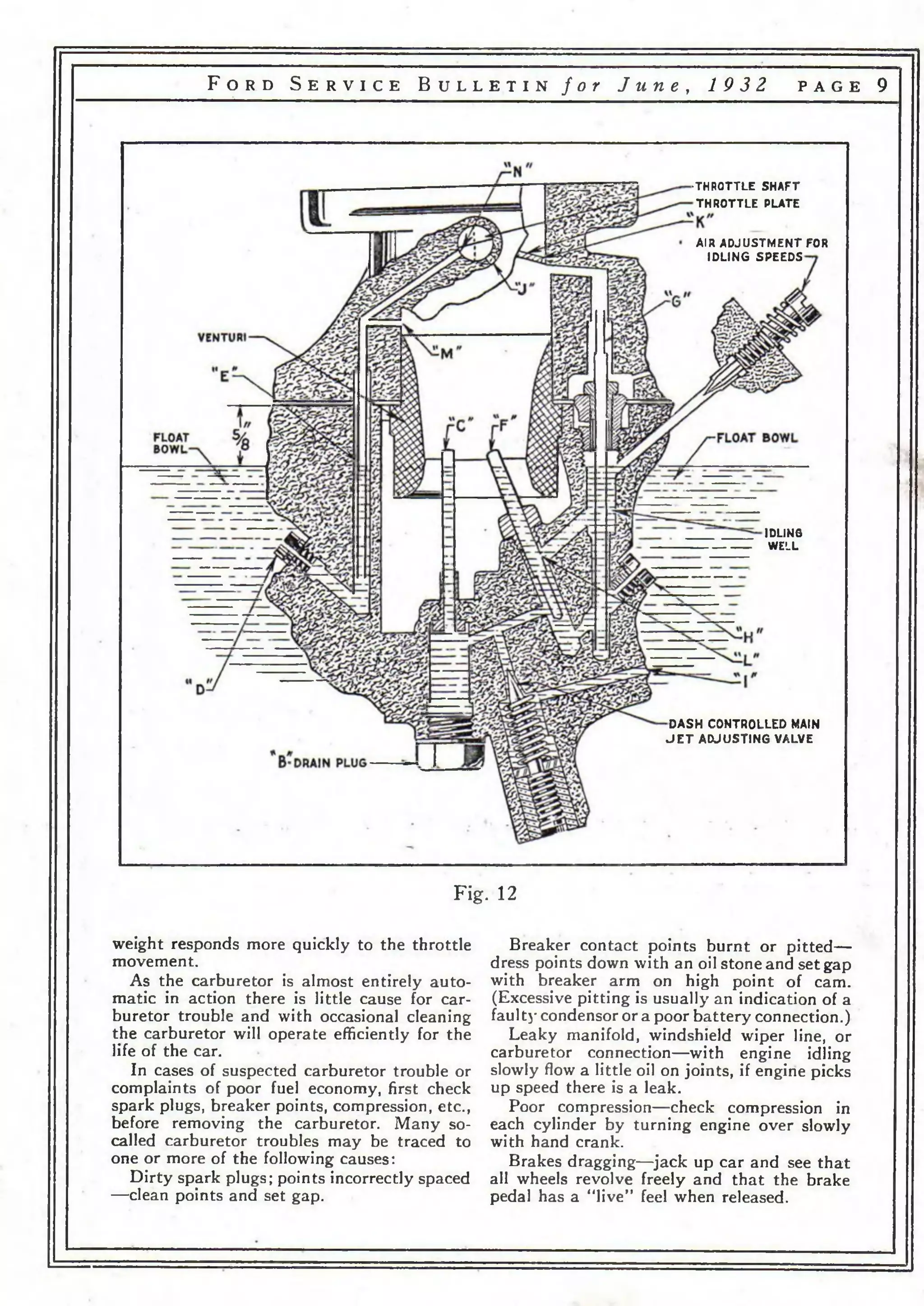
Cleaning
For complete cleaning remove the carburetor
and disassemble it by removing the
main assembly bolt. Separate the upper and
lower halves carefully to avoid damaging the
gasket, float, idling jet or power jet tubes. Remove
the plug “B” beneath the main jet and
rinse the carburetor bowl in gasoline or use air
to blow out any dirt which may have lodged in
the bottom of the bowl or in the jets. When
cleaning one of the carburetor jets, it is always
advisable to clean all of the jets and jet tubes;
in this way you may avoid the necessity of
again disassembling the carburetor.
Make certain that there is gasoline in the
tank and a free flow of fuel through the line
and that the fuel pump is functioning properly.
On complaint of lack of speed, see that the
main jet “C" and the power jet "D” and
power jet tube “E ” are free from dirt.
A plugged compensator tube “F” (Fig. 13)
will result in poor idling and low speed
performance.
The idling jet <4G,r furnishes all the fuel for
idling. Consequently the tube and metering
or cap jet “H ” must be kept clear.
The power jet “D” supplies all of the fuel
for the power jet tube "E ”
In case of leaks see that all connections and
jets are tight. If it is not functioning replace
float and float valve assembly.
On complaints of poor fuel economy make
certain that the owner understands the proper
operation of the dash adjustment as covered
in the Instruction Book.
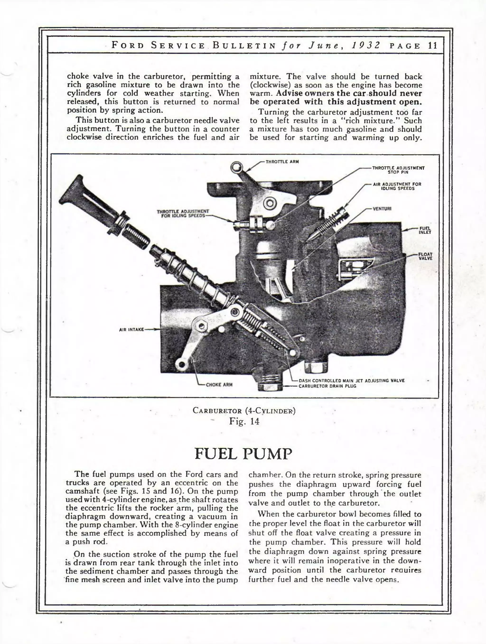
To Set Idle Adjustment
With engine warmed up, push in throttle
button on instrument panel. Adjust throttle
adjusting screw so that the engine will run
sufficiently fast to keep from stalling. Next
turn idling air adjustment screw in or out
until engine runs evenly without rolling or
skipping. (Usually from ]/i to 1% turns open
is correct.) Then slowly screw in throttle
plate adjusting screw until engine picks up a
slight additional speed.
Regulating Gasoline Mixture
The pulling out of the choke button
(located on the instrument panel) closes the
CHOKE VALVE
"M A IN J E T
f " c o m p e n s a t o r t u b e
g " i d l i n g j e t
D POWER J E T
h ” c a p j e t
Z POWER J E T T U B E
VALVE
D i s a s s em b l e d C a r b u r e t o r ( 4 -C y l in d e r )
Fig. 13](https://image.slidesharecdn.com/fordv84c1932-140907100845-phpapp01/75/Ford-v8-4_c_1932-11-2048.jpg)
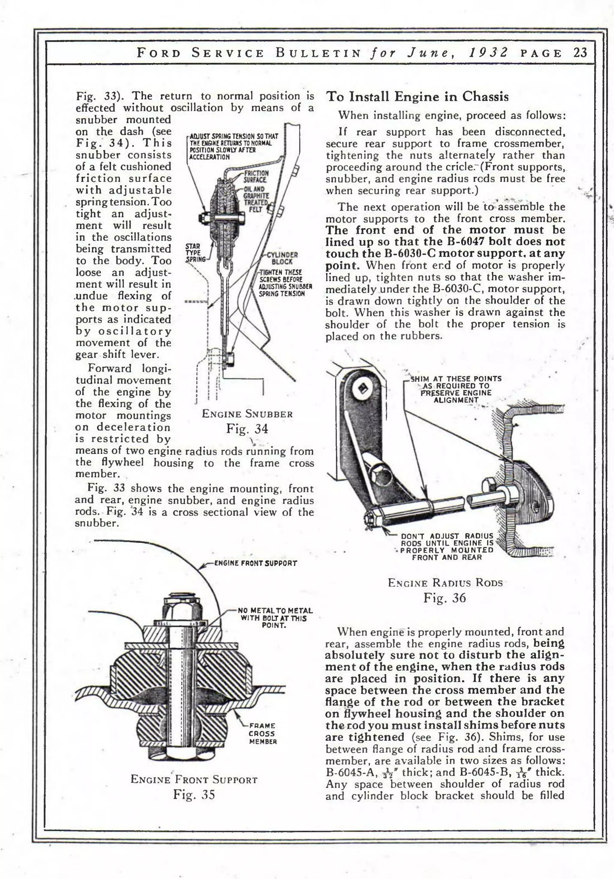
![F o r d S e r v i c e B u l l e t i n f o r J u n e , 19 3 2 p a g e 25
with xV' round washers as required. A-22310
washer is suitable for this purpose.
Next bolt the arms of the B-6800 engine
snubber to the flywheel housing, being careful
to see that there is no tension on the springs
until the arms have been bolted. After the
arms are secured, adjust the snubber spring
tension so that the engine’s return to normal
position after acceleration requires approximately
5 times as long as the original movement
(see Fig. 34).
Always remove all tension from the snubbing
unit springs if the engine mounting or engine
radius rods are being disturbed in anyway.
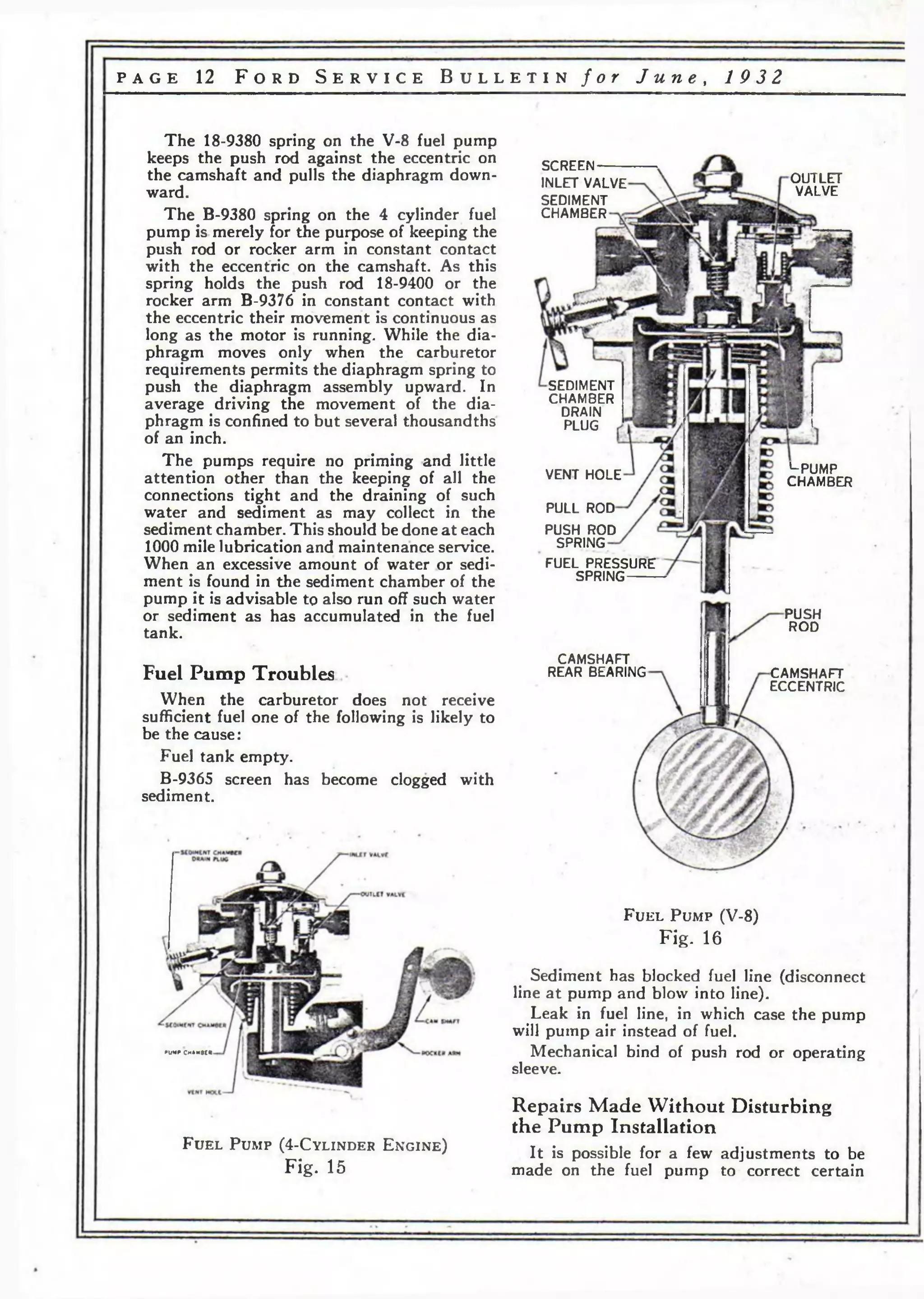
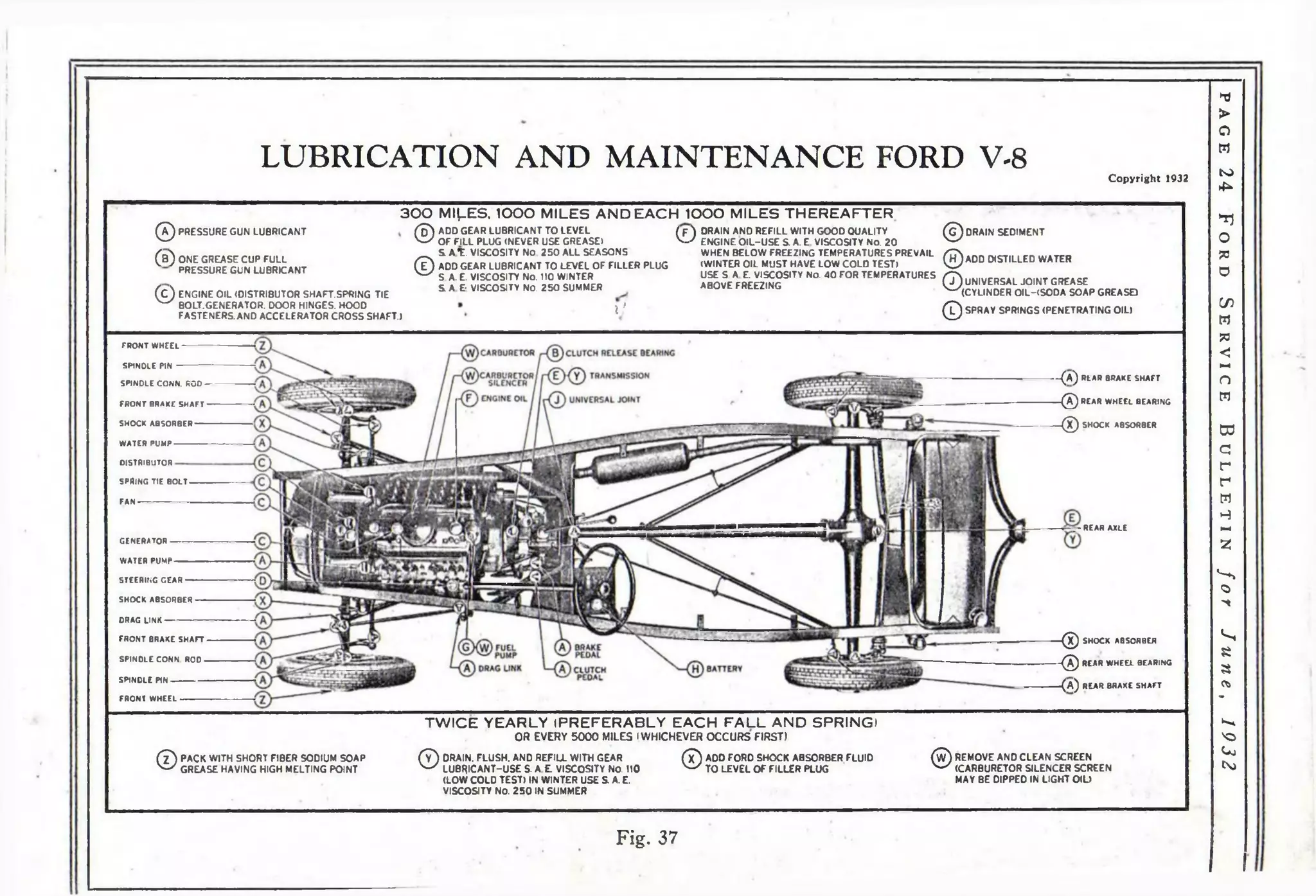
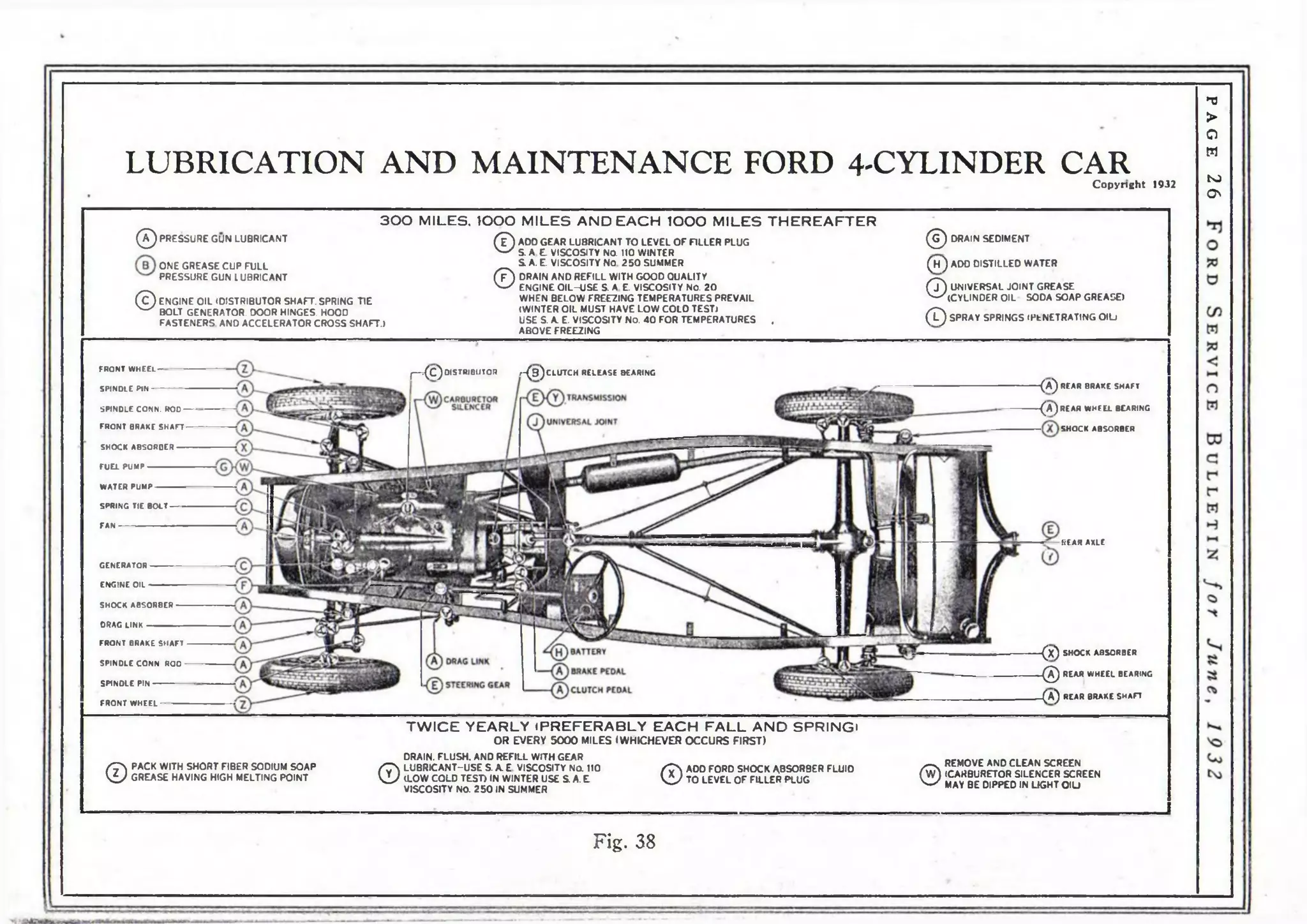
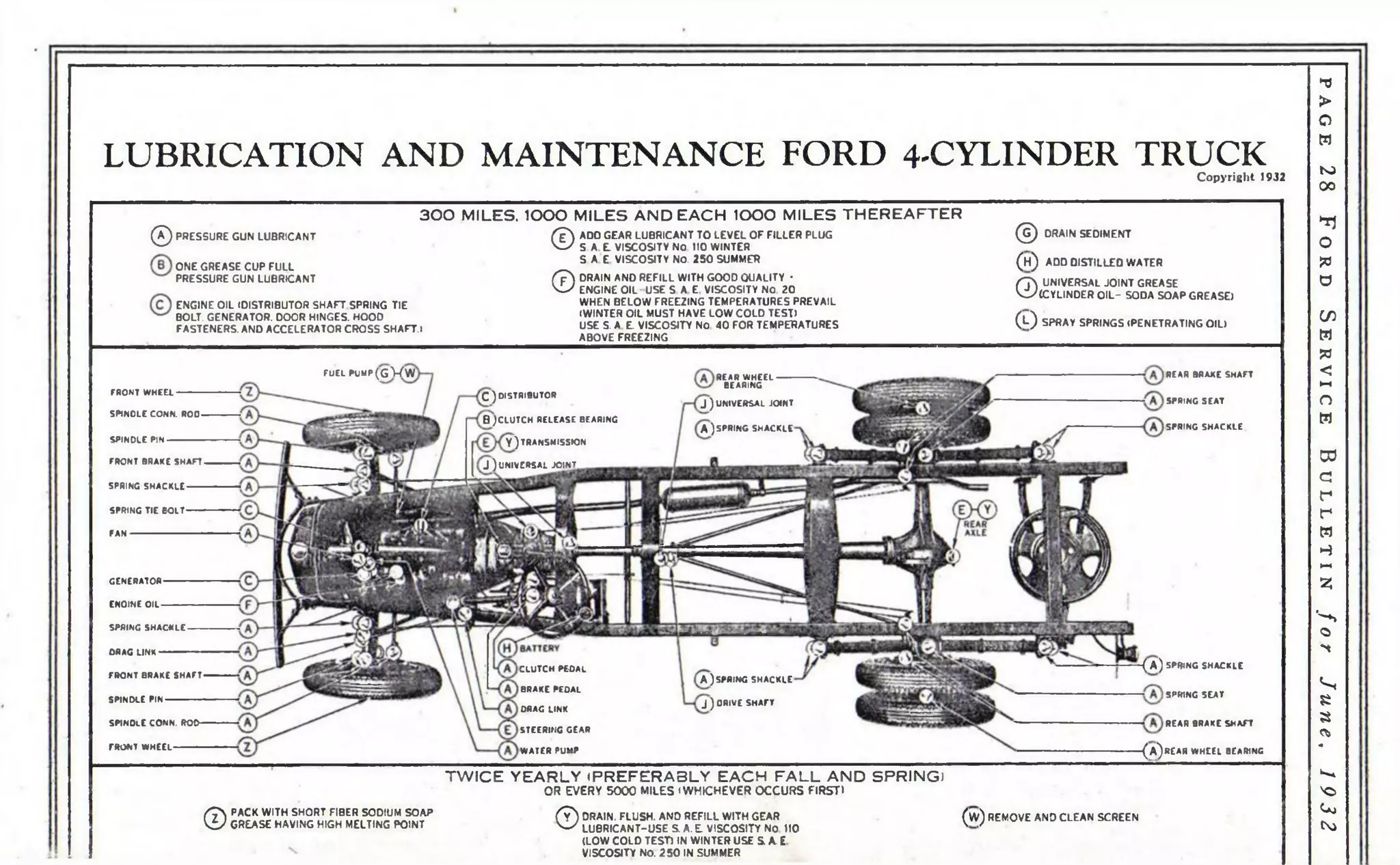
LUBRICATION AND MAINTENANCE
The importance of proper lubrication and periodic inspection and adjustments cannot be
over-emphasized. The lubrication and maintenance work on the Ford cars and trucks can
be divided into two groups: first, points requiring attention every 1000 miles; second, points
requiring attention twice yearly or every 5000 miles (whichever occurs first).
The lubrication charts, Figs. 37, 38 and 39, give information for the complete lubrication of
the cars and trucks. Proper lubrication has a vital effect on the life of any machine, consequently
you should follow these instructions very carefully.
Group 1
AT 300 MILES, 1000 MILES AND EACH
1000 MILES THEREAFTER.
Engine
Drain off the old oil w'hen the new car has
been driven 300 miles, and again when a total
mileage of 1000 miles has been reached and at
each 1000 miles thereafter. The qil will drain
out more completely if warm, ancl should be
replaced with 5 quarts of engine oil of the
proper viscosity and quality. In general, an oil
having the body of S. A. E. viscosity No. 40
will prove satisfactory for summer use. For
winter use, oil having the specifications of
S. A. E. viscosity No. 20 should be used. It is
essential, however, that this winter oil have a
low cold test. It must be understood that these
classifications are of “body” only and not of
quality. It is also essential that the oil be
otherwise properly refined.
Advise owners that oil level should be checked
periodically between changes.
Chassis
The chassis should be lubricated at 1000
miles and after each 1000 miles of operation
thereafter. Suggest that the lubrication of the
chassis and the changing.of engine oil be performed
at the same time.
Clutch Release Bearing
The clutch release bearing is lubricated by
means of a grease cup, located on the top of
the clutch housing (on the earlier V-8 cars
this grease cup is located on right side of clutch
housing). The cup should be screwed in as far
as it will go, then backed off and repacked
with a good grade of pressure gun lubricant
and replaced, screwing it in 2]/2 to 3 turns.
Steering Gear
Remove the plug on the steering gear housing
and add gear lubricant until it reaches the
level of the filler plug hole. Use gear lubricant
only, never use greases in the steering gear.
Generator
The bearings in the generator are lubricated
through a small oil hole, located at both ends
of the generator. Fill with engine oil.
Distributor
Fill the oil cup at the side of the distributor
with engine oil. A light film of vaseline should
be applied to the cam.
Transmission and Rear Axle
Sufficient gear lubricant should be added
to bring it level with the filler hole.
Universal Joint
The universal joint housing should be filled
with a universal joint lubricant composed of
cylinder oil, thickened with sodium tallow
soap. Pressure gun lubricator fittings are provided.
(3 fittings on truck, see Chart.)
Pressure Gun Fittings
Force pressure gun lubricant to all parts
equipped with the conical shaped lubricator
fittings (except universal joints). (See Charts
for locations.)
Clutch and Brake Pedals
On the earlier cars and trucks the pedal
shaft was provided with a pressure gun fitting.
A fitting is now provided on each pedal.
Fan
The fan on the V-8 operates on the generator
shaft (see Generator). The fan on 4-cylinder
engine is provided with a pressure gun fitting.](https://image.slidesharecdn.com/fordv84c1932-140907100845-phpapp01/75/Ford-v8-4_c_1932-26-2048.jpg)
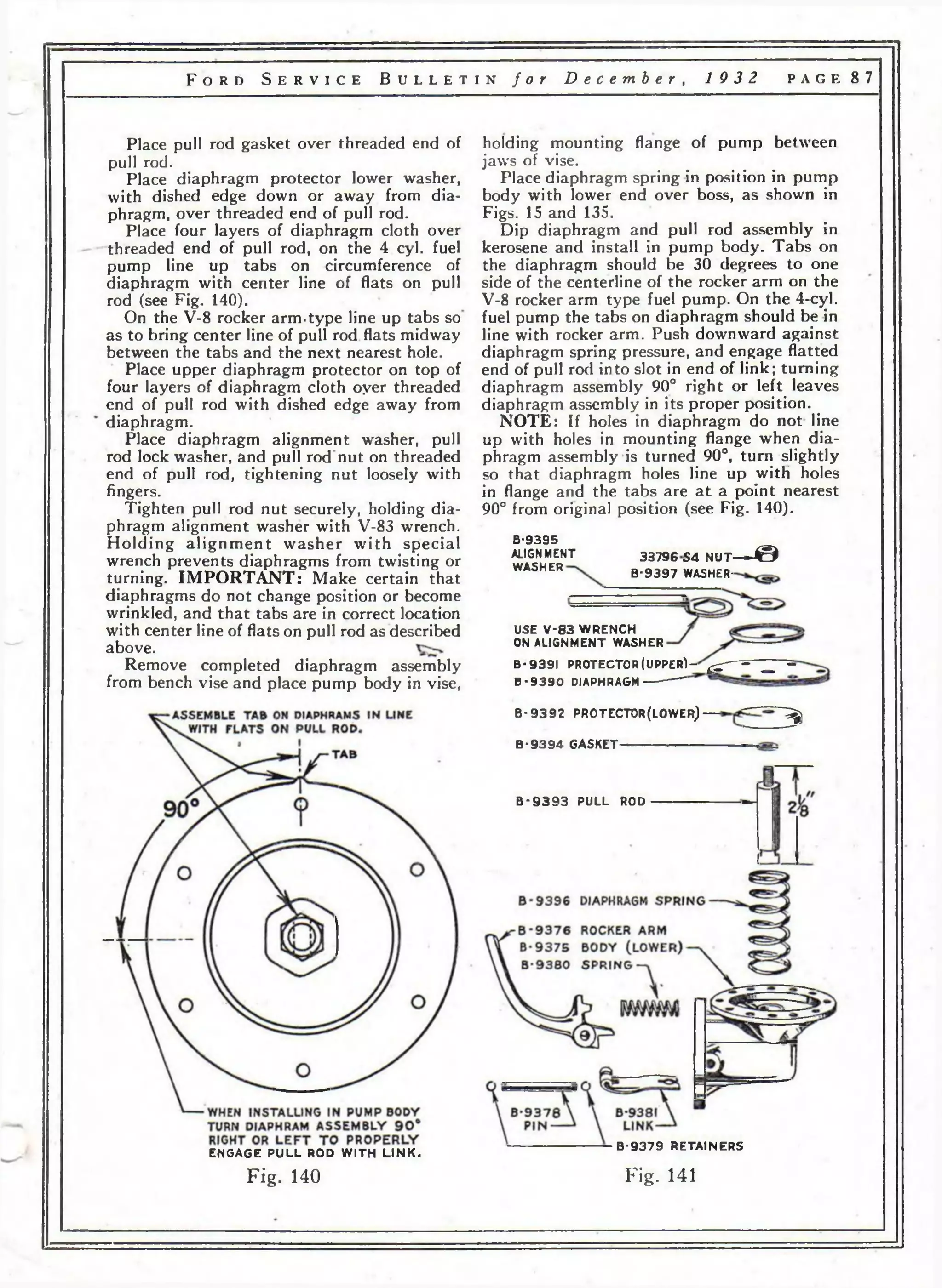
![C L U T C H PEDAL A D JU S TM EN T left by fuel gauge using special nuts provided
• * I , » , , ... , and lock washers from When adjusting clutch pedal as outlined on # removed fuel &g augг>e.
page 3 3 of the July issue of the S e r v ic e Remove radiator hose and with sharp knife
B u l l e t in , make the adjustment so as to cut a hole in hose from motor end of
obtain 134" free movement. Readjust at any hose (see Fig. 85). Wet knife blade for ease in
time when the free movement becomes less cutting.
than one inch. Place adaptor in hose (from inside of hose).
Check this adjustment on all cars coming Secure adaptor and washer in place by screw-into
your establishment for service or inspec- ing adaptor nut down tight, then replace
tion and adjust as outlined above. This is' radiator hose and insert bulb in adaptor and
particularly important on new cars and trucks tighten down bulb nut. (Loop excess tubing
or on cars and trucks in which a new clutch as in Fig. 85.)
disc has been installed. As the initial wear or
burnishing in of the clutch disc decreases the
amount of free movement of the clutch pedal.
Failure to maintain correct clutch
pedal adjustment may result in failure
of the clutch release bearing.
Fig. 85
Clip tubing to tie rod and insert grommet
in hole in dash (see Fig. 85).
Remove nut and cone from brass tube at
back of fuel gauge and set Jiquid in indicator
to zero by adding or removing from brass
tube. (Use toothpick or match to absorb surplus
liquid. If necessary to add liquid to obtain
correct reading [zero], take the liquid required
from the brass tube of gauge removed.) (Complete
fuel gauge service information was given
in June issue of Service Bulletin.)
Reconnect air line and bring fuel gauge
indicator up to proper reading on passenger
cars by disconnecting gas line at fuel pump
and blowing back through gas line into gas
tank with mouth. (Do not use compressed air.)
For trucks driving is best manner to establish
reading, turning corners frequently will hasten
this action.
Refill radiator, and installation is complete.
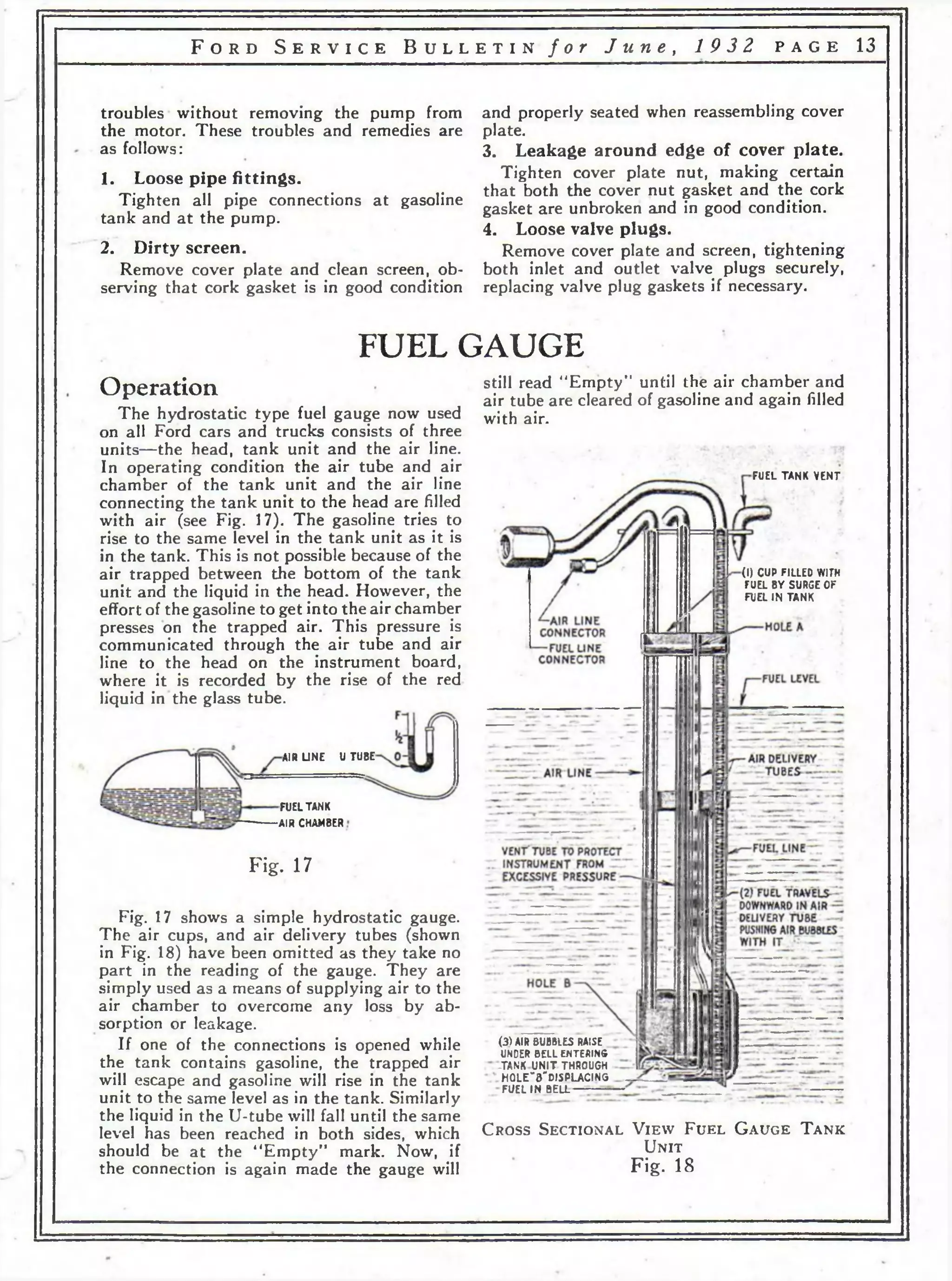
TOOLS
WAT ER T EM P E R A TU R E G A U G E
• A combination fuel and water temperature
gauge (see Fig. 84) is now available for sale
through service for either V-8 or improved
4-cvlinder cars. To install proceed as follows:
Drain cooling system, disconnect air line from
standard fuel gauge head unit and remove
head unit.
Remove the rubber plug from unused hole
in dash (not instrument panel, see Fig. 85)
cut dash insulation in back of hole. Increase
the size of this hole t^>. one inch diameter (a
round file is satisfactory'for this operation).
The increasing of the size of this hole is
necessary to permit the bulb and nut to pass
through the dash.
Uncoil gauge, push bulb and tubing through
;hole in dash. Next mount gauge in opening
Fig. 84
Tools referred to in these Bulletins are
available from K. R. Wilson, Buffalo, N. Y.,
unless otherwise specified. The tool numbers
given being the catalog number by which each
tool is identified.](https://image.slidesharecdn.com/fordv84c1932-140907100845-phpapp01/75/Ford-v8-4_c_1932-53-2048.jpg)
![F ord S e r v ic e B u l l e t in for September-October, 1932 p a g e 6 3
18-9578 KICKER (F L A T TYPE AS SUPPLIED FOR SERVICE)
18-9597
31037-S2
THIS END ASSEMBLED TO TH R O T TL E LEVER
PROGRESSIVELY LOCATED CHOKE
VALVE AIR BLEED OPENINGS
-18-9525 METERING PIN ASSY
REPLACES TH E S E PARTS
USE V-71 END
SPANNER WRENCH
18-9579 PIN
18-9580
18-9590
METERING PIN
PACKING NUT
WICK PACKING
CHECK VALVE
USE V-71 END
SPANNER WRENCH
18-9559-A
18-9539
31646-S
34805-S2
AIR VANES MUST WORK FREELY
18-9519 GASKET
EXAMINE THIS GASKET
FOR AIR LEAK IF ENGINE
DOES NOT IDLE WELL
34805— S 2
18-9543 HOLD THIS ARM BEHIND AIR
VANE WHEN ASSEMBLING UPPER B 0 D Y ~ r
MUST BE IN VERTICAL POSITION У
18-9570 AS SUPPLIED FOR SERVICE
USED WITH F LA T KICKER BAR 18-9578
ORIGINAL DESIGN
ACCELERATING PUMP PISTON
NOW OB SO LE TE
. - ■ — 18-9572 PISTON LARGE.ONLY THIS
TYPE SUPPLIED FOR SERVICE
18-9571 USED WITH EITHER PISTON
• - • «
31045— S2 SCREW % LONG
31077— S2 SCREW LONG
18-9559-B
.— OR
R A TCH E T LO C ATED
ON COVER
18-9561 GA SKET
ORIGINAL DESIGN NOW
OB SOLE TE USE
18-9550
LUGS IN FLOAT
LEVER. FIT
RECESS IN F LO A T
VALVE PIN
F LO A T VALVt(ORIGINAL]
(USE V-72 WRENCH)
THIS PART INCORPORATED
_ IN CASTING ON LATER
CARBURETORS
18-9569-A(ORIGINAL)
F LO A T VALVE
NOW USED N O T
INTERCHANGEABLE
WITH FORMER TYP E
-U S E V-72 WRENCH
18-9542
18-9516 GASKET
18-9586
18-9585 TH R O T TL E PLATE
18-9562-A PLUG
18-9563-A GASKET
34803— S 2
31628— S 2
31077-S2
18-9581 TH R O T TLE LEVER USED
WITH F LA T KICKER BAR 18-9578
A— 20107-S2
18-9569 B (N EW )
18-9558-B
18-9562-B PLUG
18-9563-B GA SKE T
v , TH E S E USED ON EARLY
Г ~ CARBURETORS ONLY
Fig. 104](https://image.slidesharecdn.com/fordv84c1932-140907100845-phpapp01/75/Ford-v8-4_c_1932-64-2048.jpg)
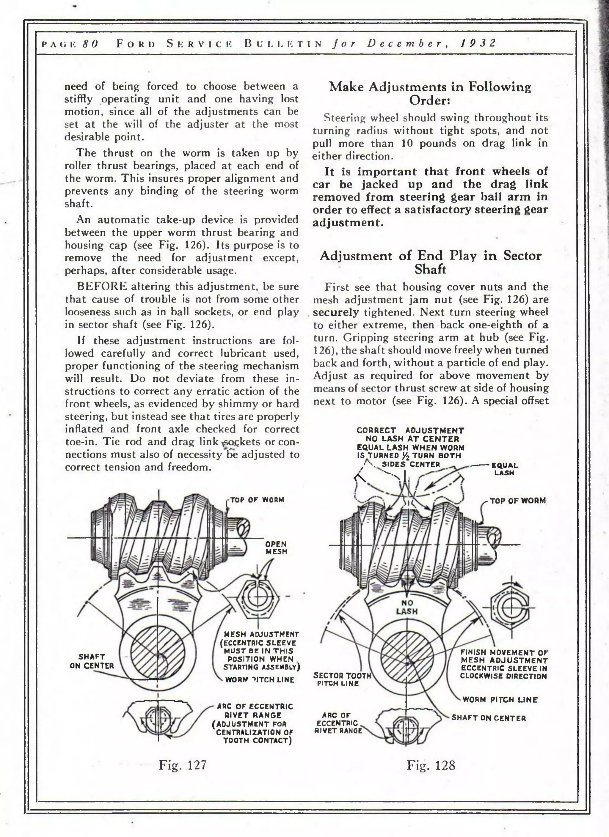
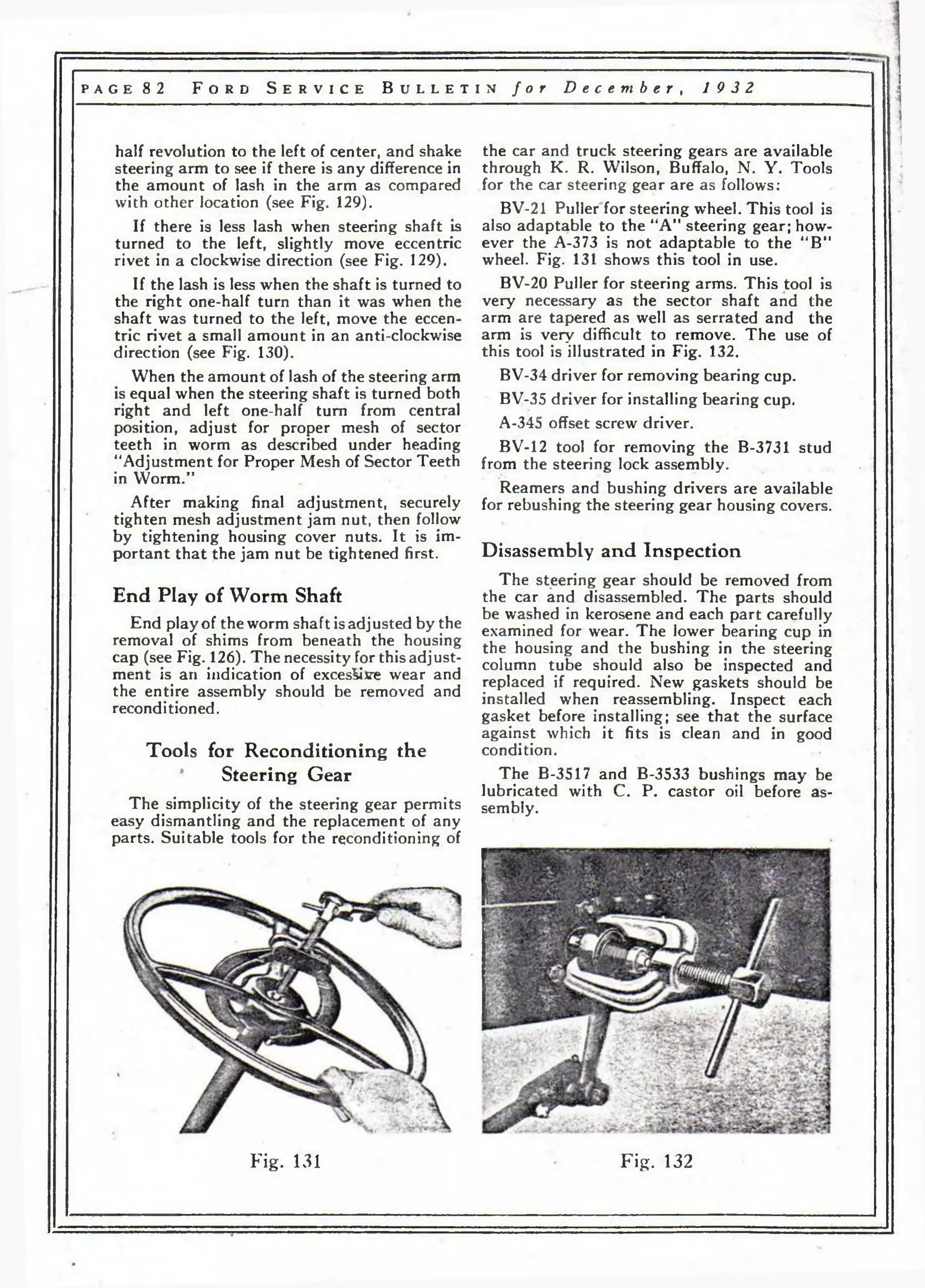
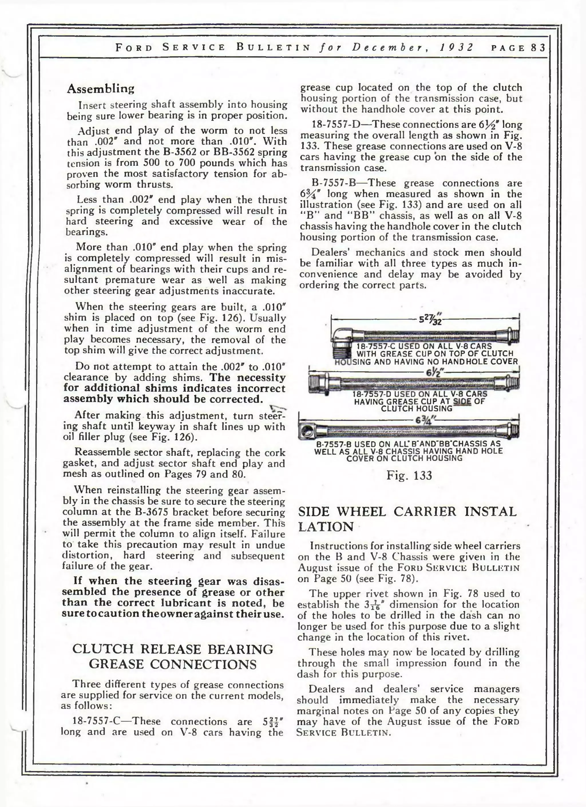
![F o r d S e r v i c e B u l l e t i n f o r D e c e m b e r , 19 3 2 p a g e 81
screw driver, A-345, is required for this purpose.
After making adjustment, be sure to tighten
lock nut (see Fig. 126), then reinspect for end
play and freedom.
Adjustment for P roper Mesh of Sector
Teeth in Worm (
Turn steering wheel to thfe mid-position of
its complete travel or turning limits. (Drag
link disconnected.) Shake steering arm to
determine amount of lost motion. Next loosen
the three housing cover nuts exactly one-quarter
turn, then loosen mesh adjustment
jam nut one-half turn. Turn the eccentric
adjusting sleeve clockwise, very gradually,
checking at each movement the amount of
lost motion still existing at the steering arm.
Adjust only sufficiently tight to eliminate all
lash of steering arm (no more), being sure
to finish movement of eccentric adjustment
sleeve in clockwise direction. Turn
steering wheel throughout full travel to test
for free operation. If too tight, turn eccentric
adjusting sleeve counter-clockwise to free and
readjust, as above, more carefully. Next securely
tighten mesh adjustment jam nut (^*tg.
126) and follow by tightening housing cover
nuts. It is important that the mesh adjustment
nut be tightened before tightening
housing cover nuts.
The worm is machined in such manner that
close mesh with sector teeth is provided at the
mid-position or place corresponding to the
straight ahead driving range with gradual
relief toward the extremes. Since any normal
wear is most pronounced at mid-position, this
provision allows for subsequent adjustment
without fear of binding toward the extremes.
When the sector teeth are properly centralized
in relation to the worm thread, there
should be an equal amount of lash in the mesh
of these parts at one-half turn of hand wheel
each side of mid-position previously described.
If this is not the case, correct as follows:
“Centralization of Tooth Contact”
(Seldom Required)
Start check at center of worm (see Fig. 128)
as indicated by keyway being in line with
filler plug (see Fig. 126).
Turn steering shaft exactly one-half turn
to right and shake steering arm to note
amount of play or lash.
Then turn the shaft back to the left one
complete revolution, or in other words, one-
TOP O F WORM
TURN CLOCKWISE TO CORRECT
TURN T IG HT
(N O T ENOUGH l a s h )
RIGHT TURN
LOOSE
MUCH
LASH)
S H A F T
OFF CENTER
WORM PITCH
L IN E
COVER
TO FAR UP
TOOTH PITCH
L INE
TOP OF WORM
TURN
LOOSE(TOO
(M U C H LASH)
RIGHT TURN
T IGH T (NOT
LASH]
Ь
WORM
PITCH LINE
SHAFT OFF CENTER
COVER
FAR
ARC OF ECCENTRIC
RIVET RANGE
TURN COUNTER-CLOCKWISE TO CORRECT
Fig. 129 Fig. 130](https://image.slidesharecdn.com/fordv84c1932-140907100845-phpapp01/75/Ford-v8-4_c_1932-82-2048.jpg)
![p a g e 8 8 F o r d S e r v i c e B u l l e t i n f o r D e c e m b e r , 1 9 3 2
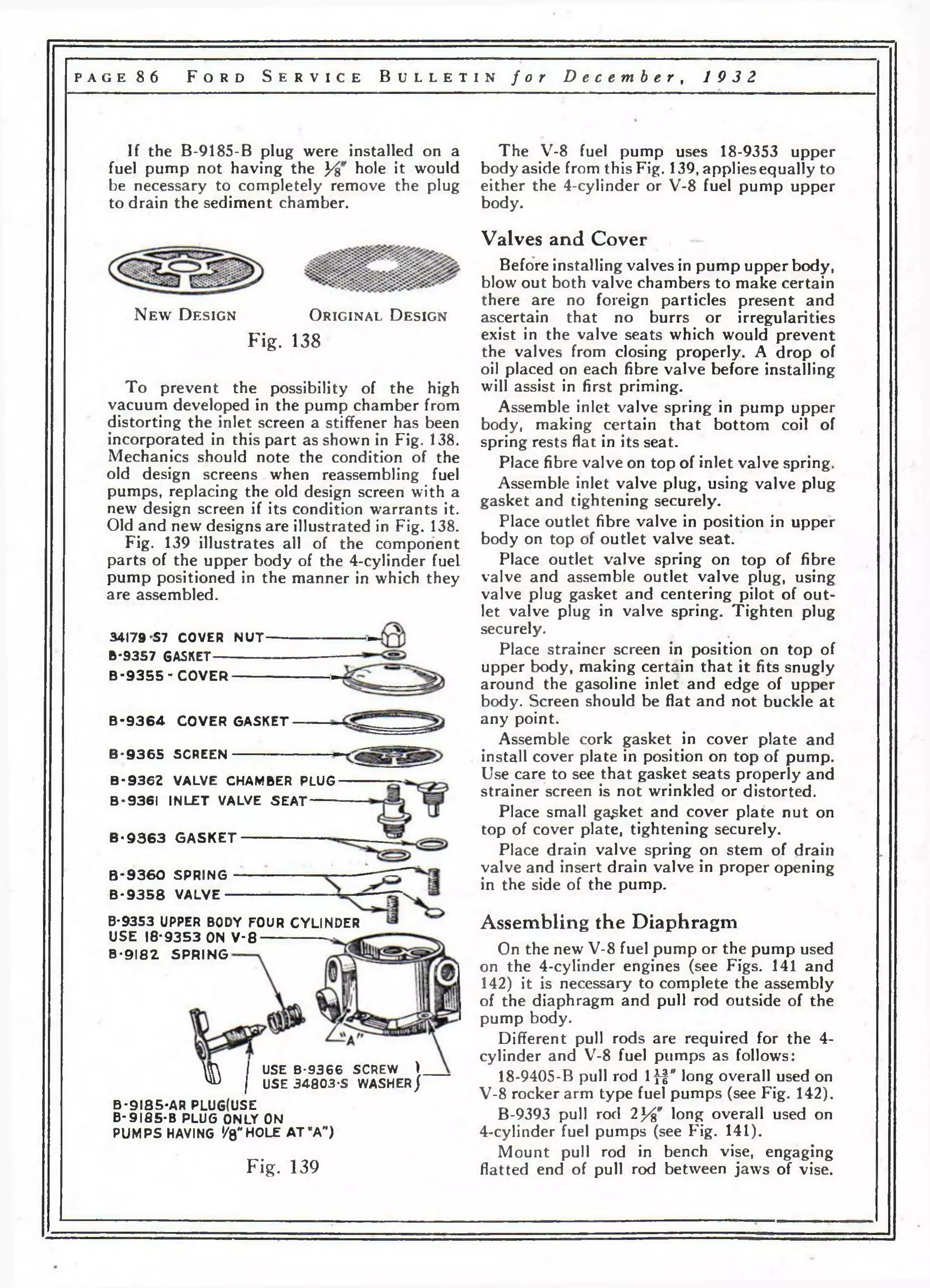
Fig. 141 illustrates all of the component
parts of the lower body of the 4-cylinder fuel
pump.
Fig. 142 illustrates all of the component
parts of the lower body of the new V-8 fuel
pump described on preceding pages (see Fig.
135).
By referring to these illustrations no trouble
should be experienced in assembling either of
these pumps.
To replace any parts of the lower body
assembly exclusive of the diaphragm assembly
on either the new V-8 or the 4-cylinder fuel
pump the rocker arm, link and spring can be
removed by removing the rocker arm and
link shafts (two shafts 18-9378 on the new
V-8 pump, one B-9378 pin on the 4-cylinder).
The B-9378 pin on the 4-cylinder pump
is held in place by two B-9379 retainers.
The 18-9378 pins on the new V-8 pump are
held in place by upsetting or swredging both
ends of the hole in the lower body.
When assembling the B-9381 link in the
4-cylinder pump be sure the loop is up as
shown in Figs. 15 and 141.
Up p e r and Lower Body Assembly
1. Place upper body assembly in proper
position on top of lower pump b6dy.
2. Drop cover screws into proper holes in
cover, using lock washers, and making certain
that screws pass through the four layers of
diaphragm correctly.
3. Tighten screws slightly so that a light
tension is placed on the lockwashers.
4. With diaphragm in its lowest possible
position (attained by pressing the rocker arm
in to the limit of its travel [see note on Fig.
135]), or at the highest possible position
(attained by pressing the 18-9383 link “in” by
means of a small rod through the hole in the
end of the 18-9377 rocker) tighten cover
screws alternately and securely.
Fuel Pump Test
There are different ways of checking the
suction and pressure of the pump when it is
not mounted on the car. One of these is to
assemble a gasoline line about three feet long
to the inlet of the pump; then by placing the
lower end of the this line in a tank of fuel and
manipulating the operating sleeve or rocker
arm, observe whether or not there is a suction
and pressure. The pump should force fuel
from the outlet opening with this method of
test, raising the fuel at least thirty inches with
a maximum of forty strokes. If fuel does not
appear on the outlet opening with this number
of strokes, the pump will not function properly
and the pump must be disassembled to locate
the cause.
A simple check of the suction and pressure
may be made by holding the fingers over the
inlet and outlet of the pump, manipulating
operating sleeve or the rocker arm. Whenever
possible, reinstall the pump on the car and
check it by watching the priming action. A
pump properly repaired and installed will
prime itself—that is, show a flow of fuel at the
outlet of the pump, when the starter is
depressed, in about twenty seconds or less.
33796-S-i NUT“ ----------------------
B-9397 WASHER--------------------------
B-9395 ALIGNMENT WASHER
USE V - 8 3 WRENCH TO
HOLD ALIGNMENT WASHER
B-9391 PROTECTOR (UPPER)
B-9390 DIAPHRAGM
USE 4 LAYERS
B-9392 PROTECTOR (LOWER)
10-9407
18-9408
B-9394 GASKET
18-94.05-B PULL ROD
18-9396-B SPRING DIAPHRAGM
18-9375-B BODY LOWER
SWEDGE END OF HOLES
TO HOLD 18-9373
PINS IN PLACE
18-9383 LINK
18*9378 PIN
18-9384 SPRING
18*9377 ROCKER
18*9378 PIN
Fig.*142](https://image.slidesharecdn.com/fordv84c1932-140907100845-phpapp01/75/Ford-v8-4_c_1932-89-2048.jpg)