In this ppt , physical mechanism of forced convection , External and Inter flow of fluids with different geometrical shapes and orientations are presented.
Contents
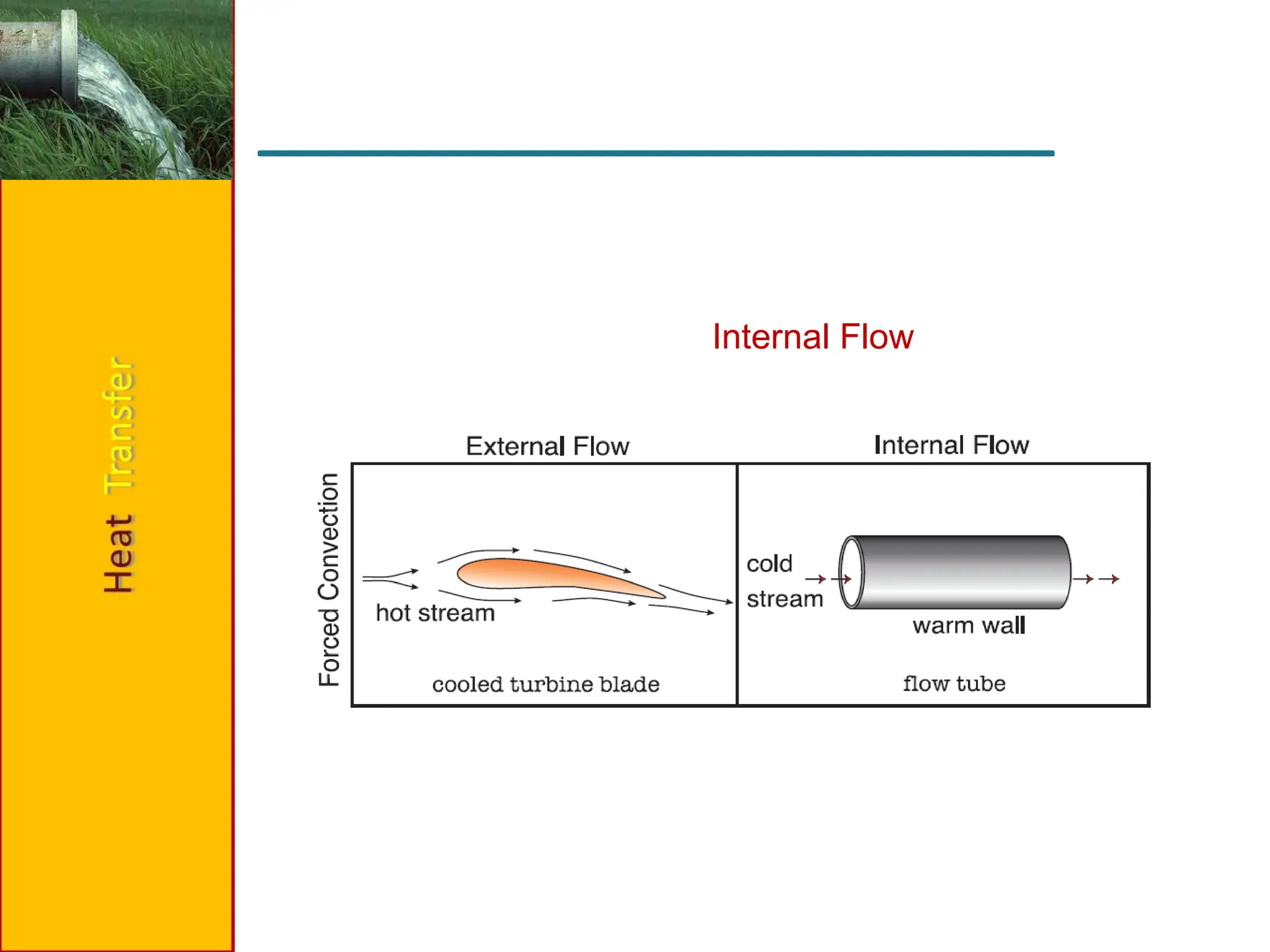
External Flows:
• Concept of hydrodynamic and thermal boundary layer
• Use of empirical correlations for flat plates and cylinders
Internal Flows:
• Concepts of hydrodynamic and thermal entry lengths
• Use of empirical relations for vertical plates and pipes
4.
convection isthe mechanism of heat transfer through a fluid in the bulk presence of
fluid medium.
Classification of convection
Convection is classified as natural (or free) and forced convection, depending on how
the fluid motion is initiated.
In forced convection, the fluid is forced to flow over a surface or in a pipe by external
means such as a pump or a fan.
In natural convection, any fluid motion is caused by natural means such as the
buoyancy effect, which manifests itself as the rise of warmer fluid and the fall of the
cooler.
Convection is also classified as external and internal, depending on whether the fluid
is forced to flow over a surface or in a channel .
Introduction
5.
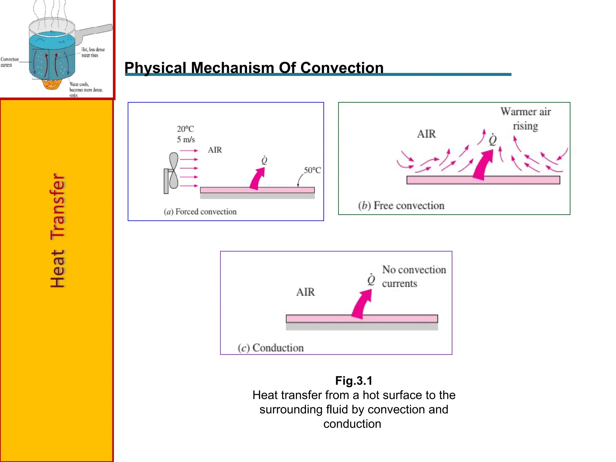
Physical Mechanism OfConvection
Fig.3.1
Heat transfer from a hot surface to the
surrounding fluid by convection and
conduction
6.
Conduction andconvection are similar in that both mechanisms require the presence
of a material medium. But they are different in that convection requires the presence of
fluid motion.
Heat transfer through a fluid is by convection in the presence of bulk fluid motion
and by conduction in the absence of it.
Convection heat transfer is complicated by the fact that it involves fluid motion as
well as heat conduction. The fluid motion enhances heat transfer, since it brings hotter
and cooler chunks of fluid into contact, initiating higher rates of conduction at a greater
number of sites in a fluid.
Therefore, the rate of heat transfer through a fluid is much higher by convection
than it is by conduction. In fact, the higher the fluid velocity, the higher the rate of heat
transfer.
7.
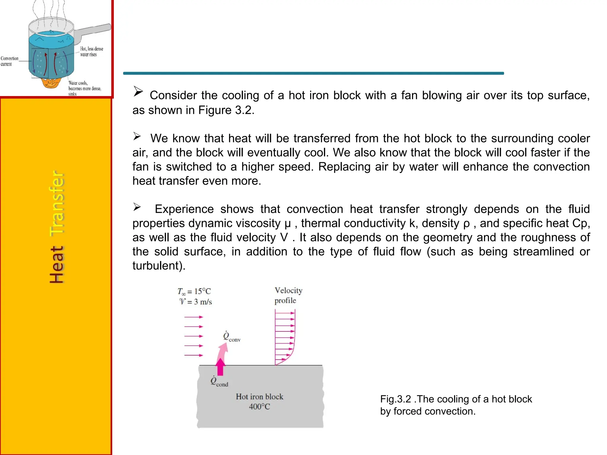
Consider thecooling of a hot iron block with a fan blowing air over its top surface,
as shown in Figure 3.2.
We know that heat will be transferred from the hot block to the surrounding cooler
air, and the block will eventually cool. We also know that the block will cool faster if the
fan is switched to a higher speed. Replacing air by water will enhance the convection
heat transfer even more.
Experience shows that convection heat transfer strongly depends on the fluid
properties dynamic viscosity μ , thermal conductivity k, density ρ , and specific heat Cp,
as well as the fluid velocity V . It also depends on the geometry and the roughness of
the solid surface, in addition to the type of fluid flow (such as being streamlined or
turbulent).
Fig.3.2 .The cooling of a hot block
by forced convection.
8.
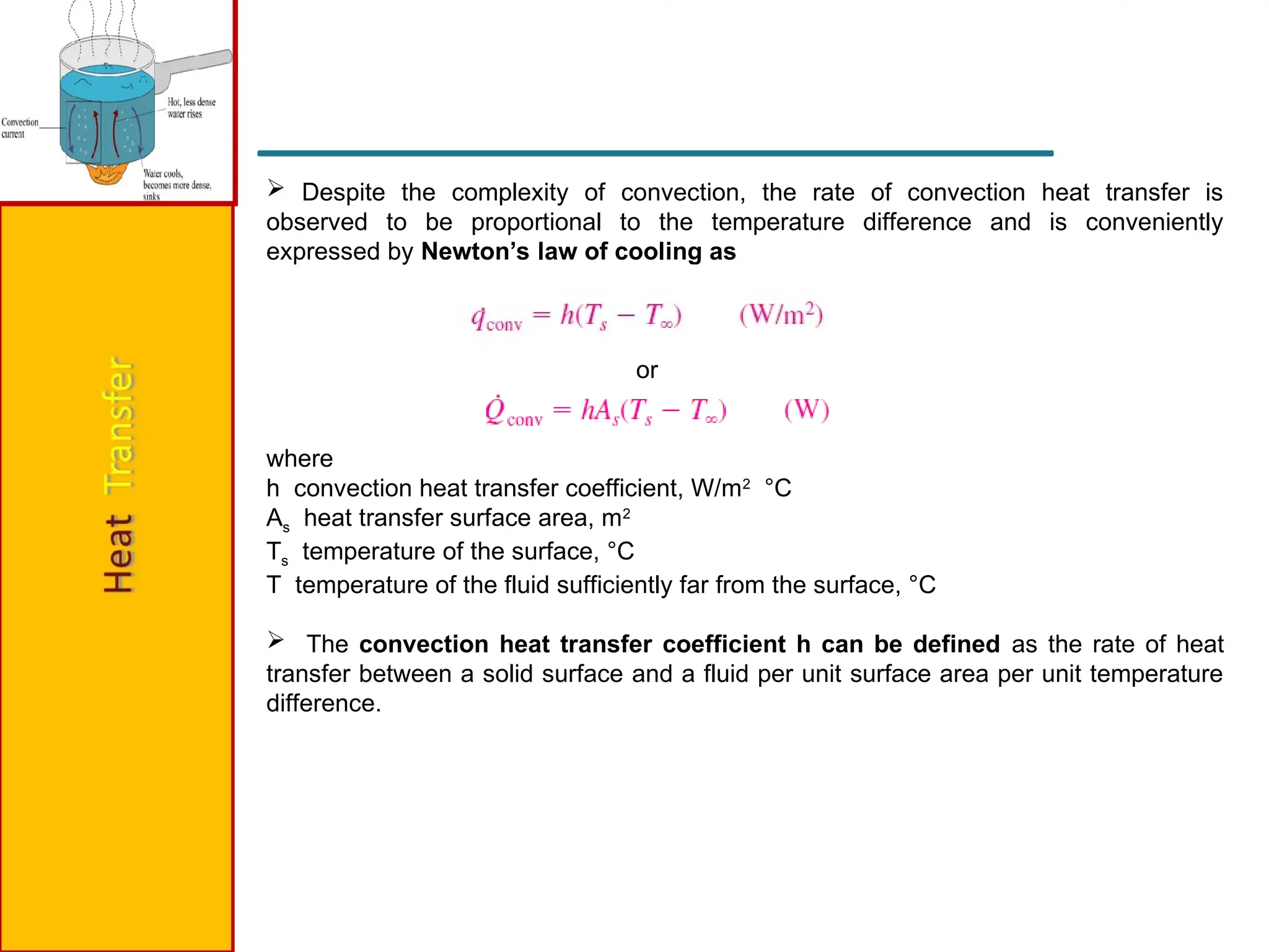
Despite thecomplexity of convection, the rate of convection heat transfer is
observed to be proportional to the temperature difference and is conveniently
expressed by Newton’s law of cooling as
or
where
h convection heat transfer coefficient, W/m2
°C
As heat transfer surface area, m2
Ts temperature of the surface, °C
T temperature of the fluid sufficiently far from the surface, °C
The convection heat transfer coefficient h can be defined as the rate of heat
transfer between a solid surface and a fluid per unit surface area per unit temperature
difference.
9.
Nusselt Number
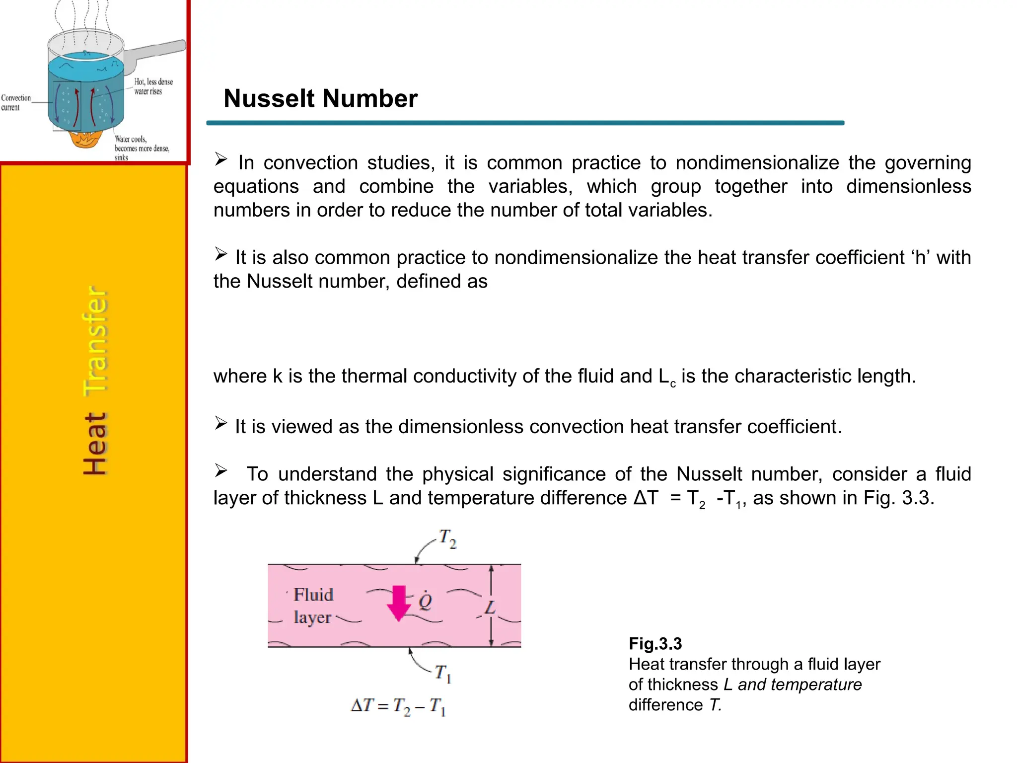
Inconvection studies, it is common practice to nondimensionalize the governing
equations and combine the variables, which group together into dimensionless
numbers in order to reduce the number of total variables.
It is also common practice to nondimensionalize the heat transfer coefficient ‘h’ with
the Nusselt number, defined as
where k is the thermal conductivity of the fluid and Lc is the characteristic length.
It is viewed as the dimensionless convection heat transfer coefficient.
To understand the physical significance of the Nusselt number, consider a fluid
layer of thickness L and temperature difference ΔT = T2 -T1, as shown in Fig. 3.3.
Fig.3.3
Heat transfer through a fluid layer
of thickness L and temperature
difference T.
10.
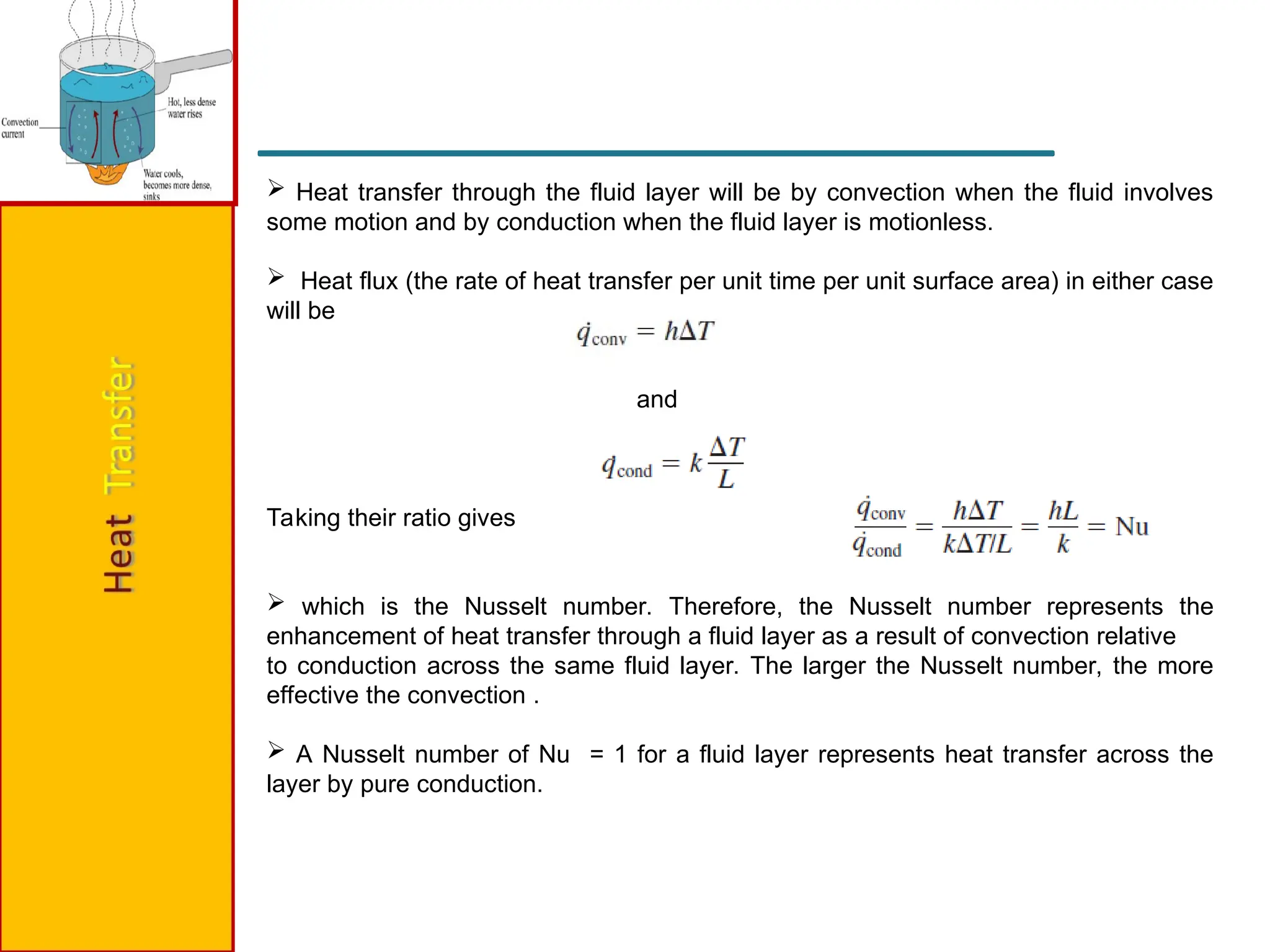
Heat transferthrough the fluid layer will be by convection when the fluid involves
some motion and by conduction when the fluid layer is motionless.
Heat flux (the rate of heat transfer per unit time per unit surface area) in either case
will be
and
Taking their ratio gives
which is the Nusselt number. Therefore, the Nusselt number represents the
enhancement of heat transfer through a fluid layer as a result of convection relative
to conduction across the same fluid layer. The larger the Nusselt number, the more
effective the convection .
A Nusselt number of Nu = 1 for a fluid layer represents heat transfer across the
layer by pure conduction.
11.
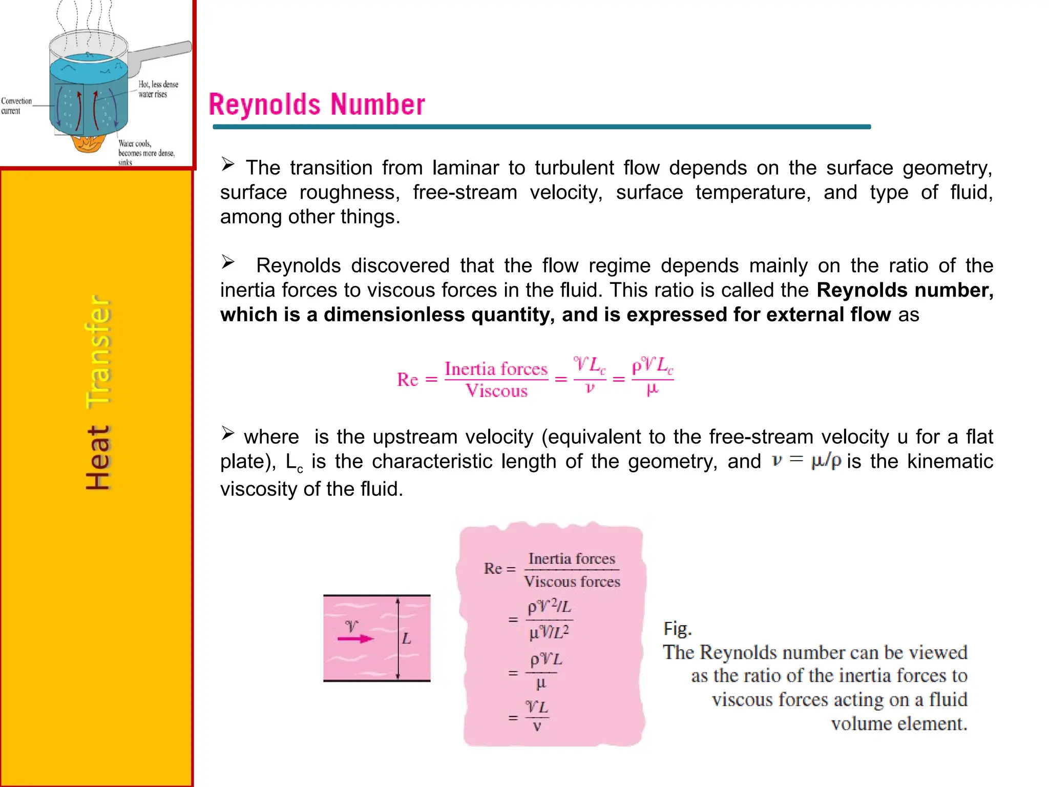
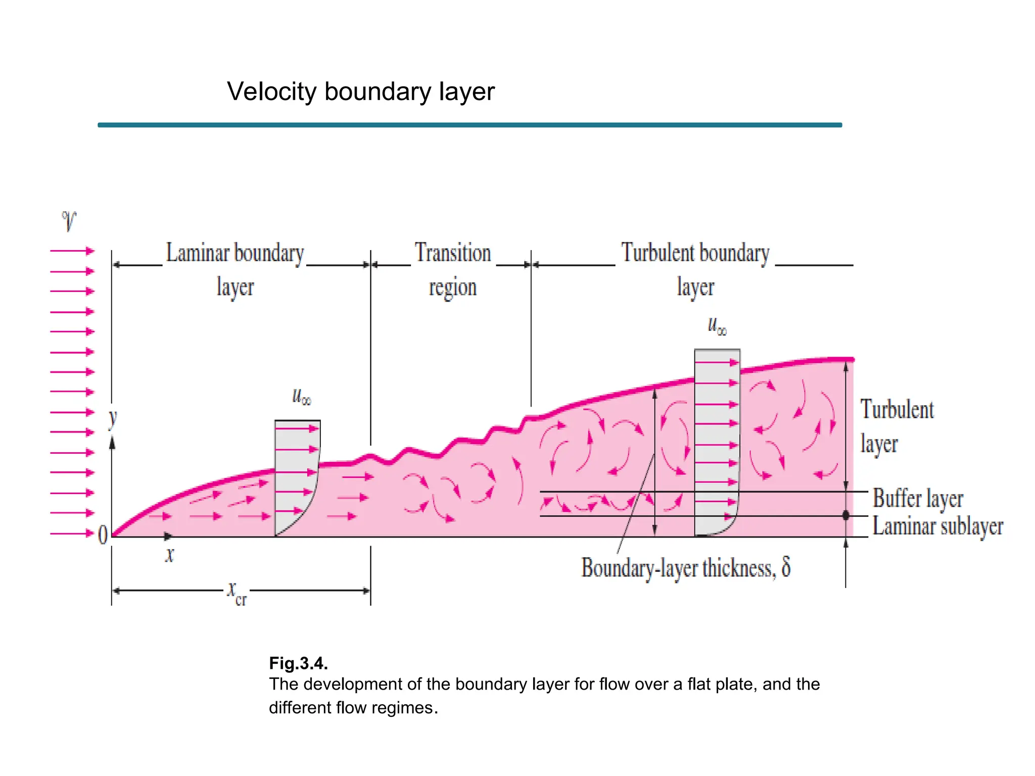
The transitionfrom laminar to turbulent flow depends on the surface geometry,
surface roughness, free-stream velocity, surface temperature, and type of fluid,
among other things.
Reynolds discovered that the flow regime depends mainly on the ratio of the
inertia forces to viscous forces in the fluid. This ratio is called the Reynolds number,
which is a dimensionless quantity, and is expressed for external flow as
where is the upstream velocity (equivalent to the free-stream velocity u for a flat
plate), Lc is the characteristic length of the geometry, and is the kinematic
viscosity of the fluid.
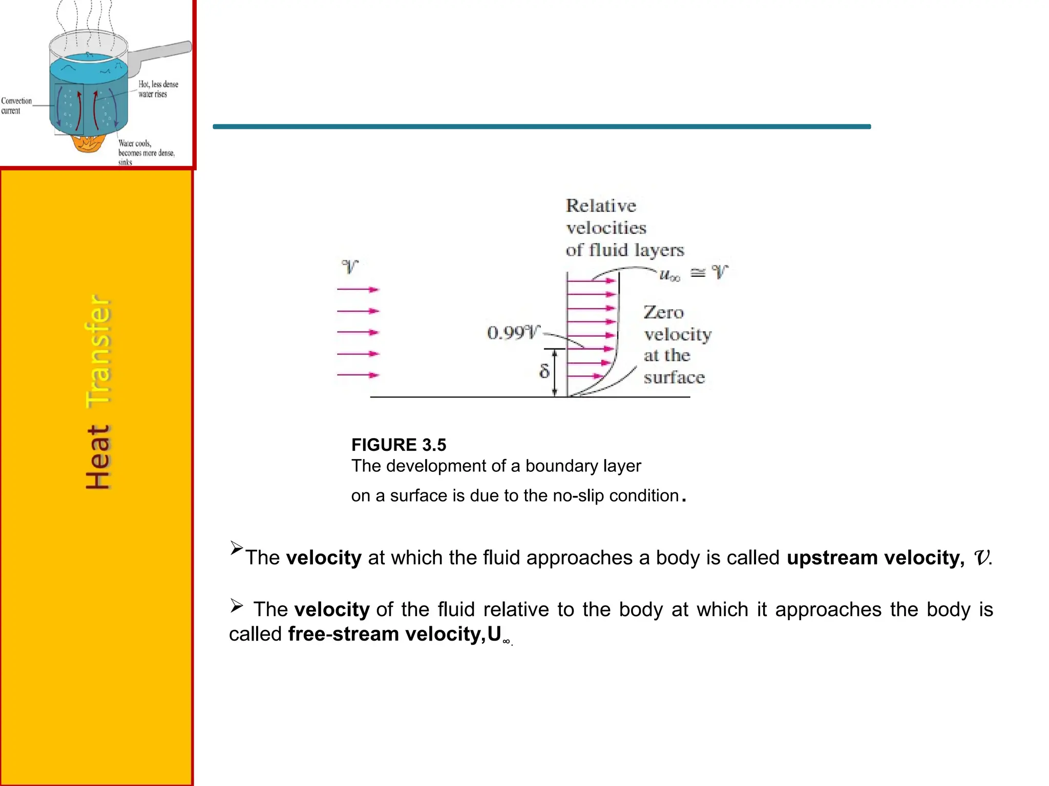
FIGURE 3.5
The developmentof a boundary layer
on a surface is due to the no-slip condition.
The velocity at which the fluid approaches a body is called upstream velocity, v.
The velocity of the fluid relative to the body at which it approaches the body is
called free-stream velocity,U∞.
14.
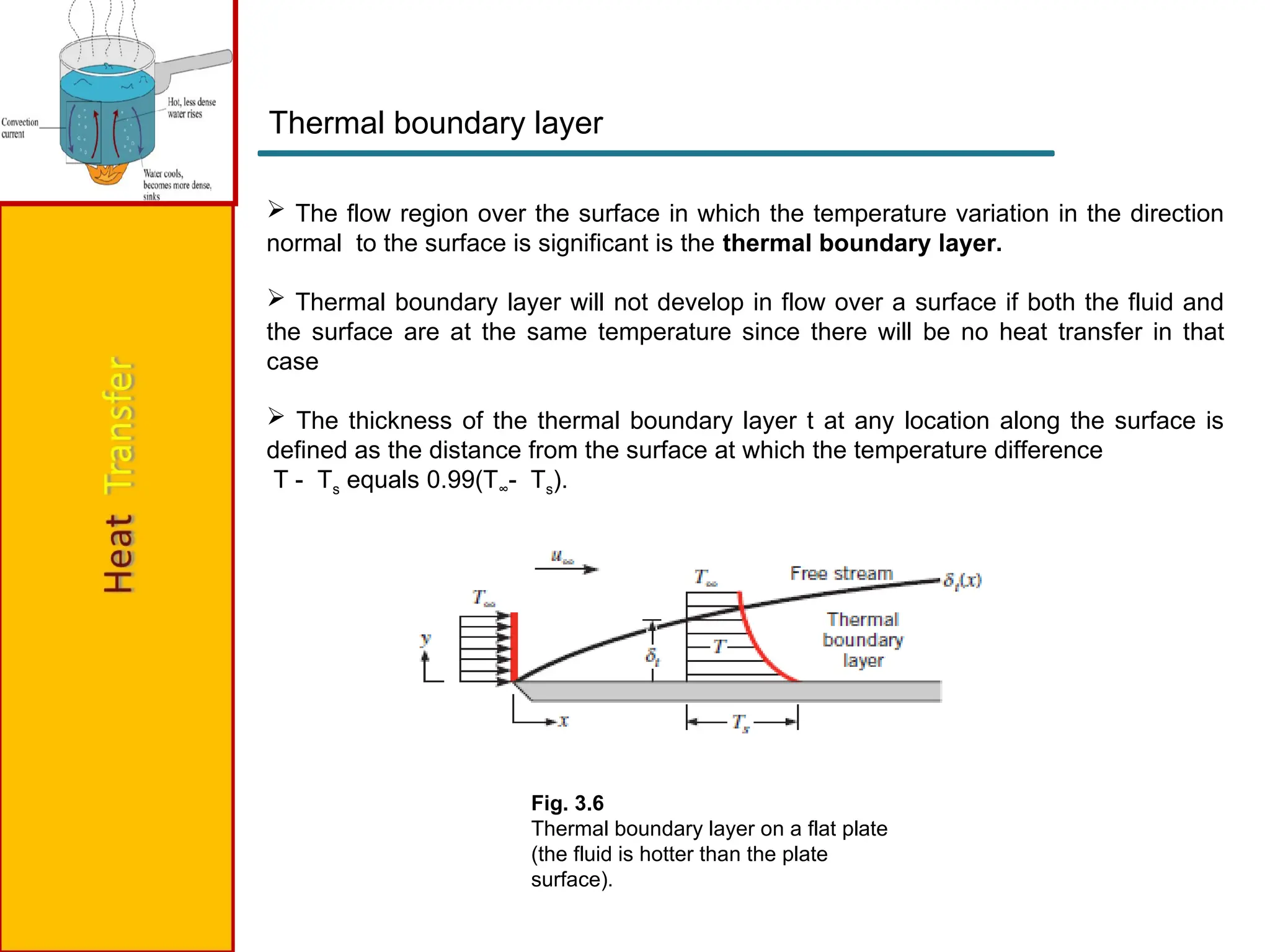
Fig. 3.6
Thermal boundarylayer on a flat plate
(the fluid is hotter than the plate
surface).
The flow region over the surface in which the temperature variation in the direction
normal to the surface is significant is the thermal boundary layer.
Thermal boundary layer will not develop in flow over a surface if both the fluid and
the surface are at the same temperature since there will be no heat transfer in that
case
The thickness of the thermal boundary layer t at any location along the surface is
defined as the distance from the surface at which the temperature difference
T - Ts equals 0.99(T∞- Ts).
Thermal boundary layer
15.
Prandtl Number
Therelative thickness of the velocity and the thermal boundary layers is best
described by the dimensionless parameter Prandtl number, defined as
16.
External Flows
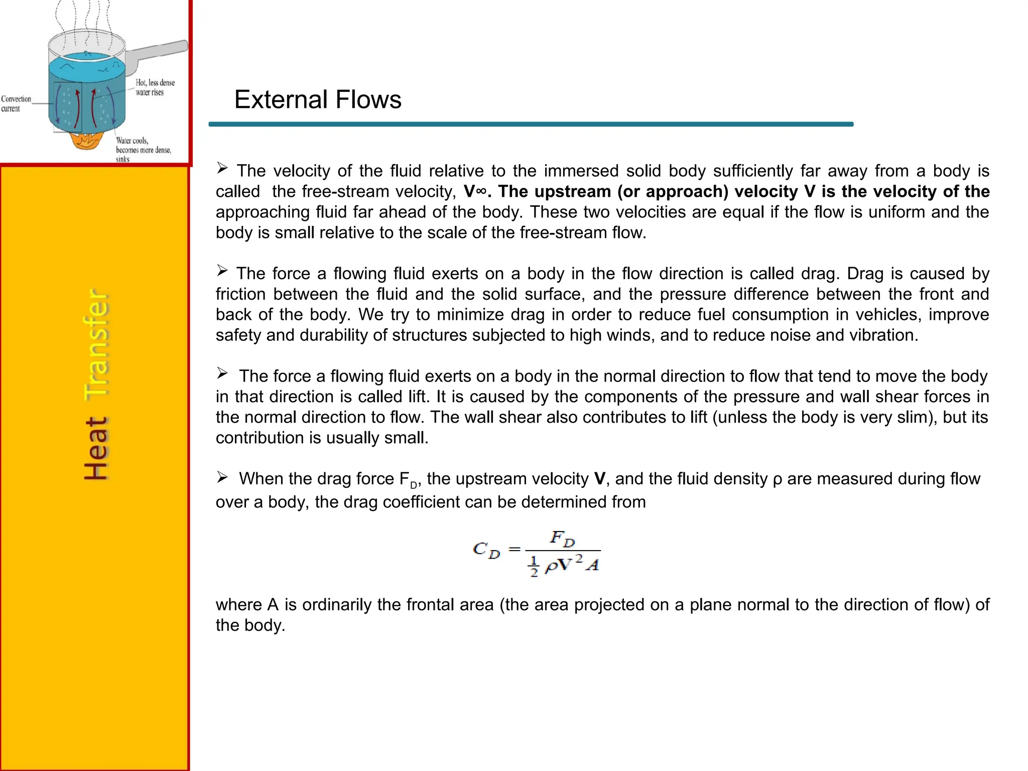
Thevelocity of the fluid relative to the immersed solid body sufficiently far away from a body is
called the free-stream velocity, V∞. The upstream (or approach) velocity V is the velocity of the
approaching fluid far ahead of the body. These two velocities are equal if the flow is uniform and the
body is small relative to the scale of the free-stream flow.
The force a flowing fluid exerts on a body in the flow direction is called drag. Drag is caused by
friction between the fluid and the solid surface, and the pressure difference between the front and
back of the body. We try to minimize drag in order to reduce fuel consumption in vehicles, improve
safety and durability of structures subjected to high winds, and to reduce noise and vibration.
The force a flowing fluid exerts on a body in the normal direction to flow that tend to move the body
in that direction is called lift. It is caused by the components of the pressure and wall shear forces in
the normal direction to flow. The wall shear also contributes to lift (unless the body is very slim), but its
contribution is usually small.
When the drag force FD, the upstream velocity V, and the fluid density ρ are measured during flow
over a body, the drag coefficient can be determined from
where A is ordinarily the frontal area (the area projected on a plane normal to the direction of flow) of
the body.
17.
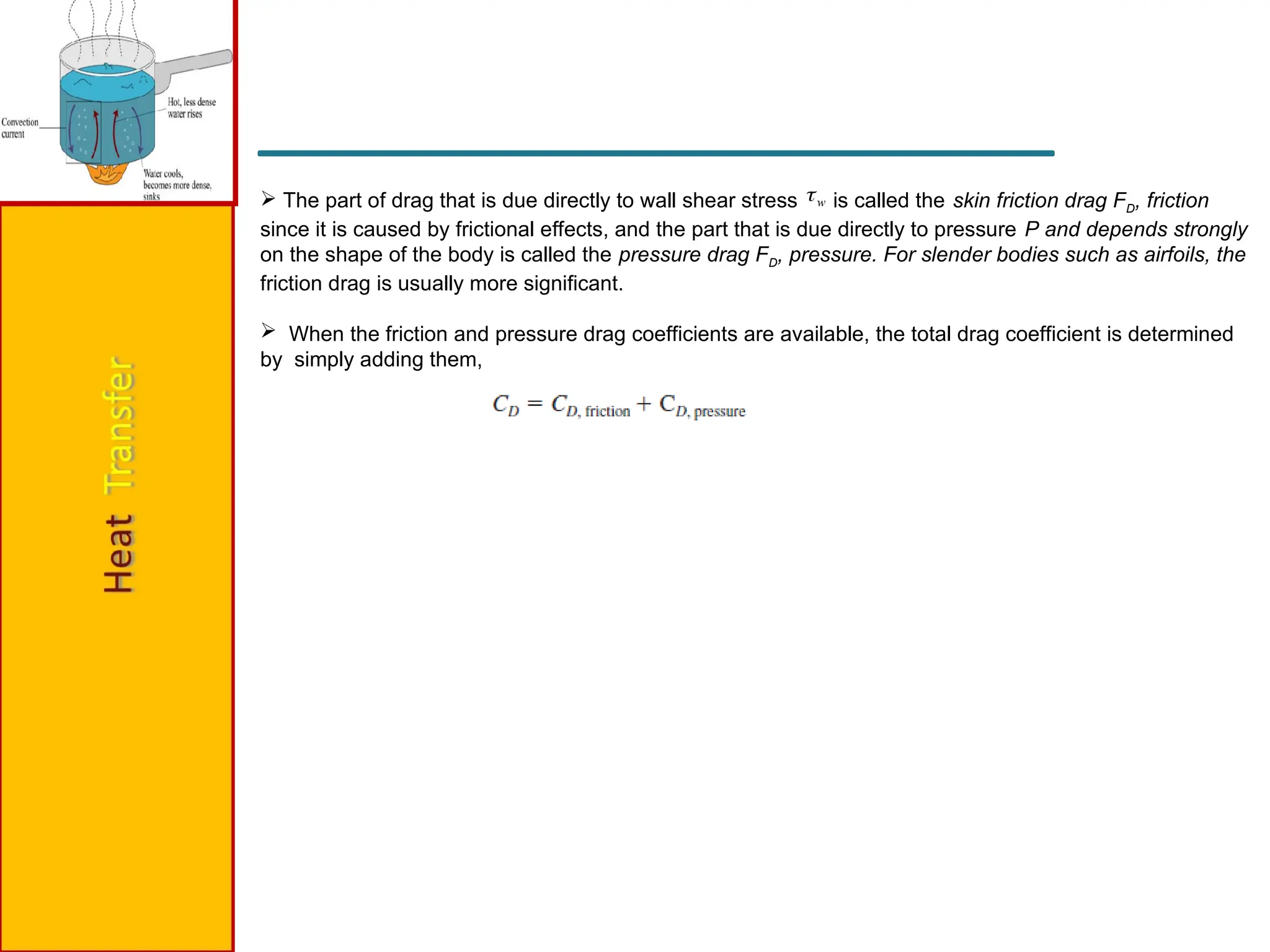
The partof drag that is due directly to wall shear stress is called the skin friction drag FD, friction
since it is caused by frictional effects, and the part that is due directly to pressure P and depends strongly
on the shape of the body is called the pressure drag FD, pressure. For slender bodies such as airfoils, the
friction drag is usually more significant.
When the friction and pressure drag coefficients are available, the total drag coefficient is determined
by simply adding them,
w
18.
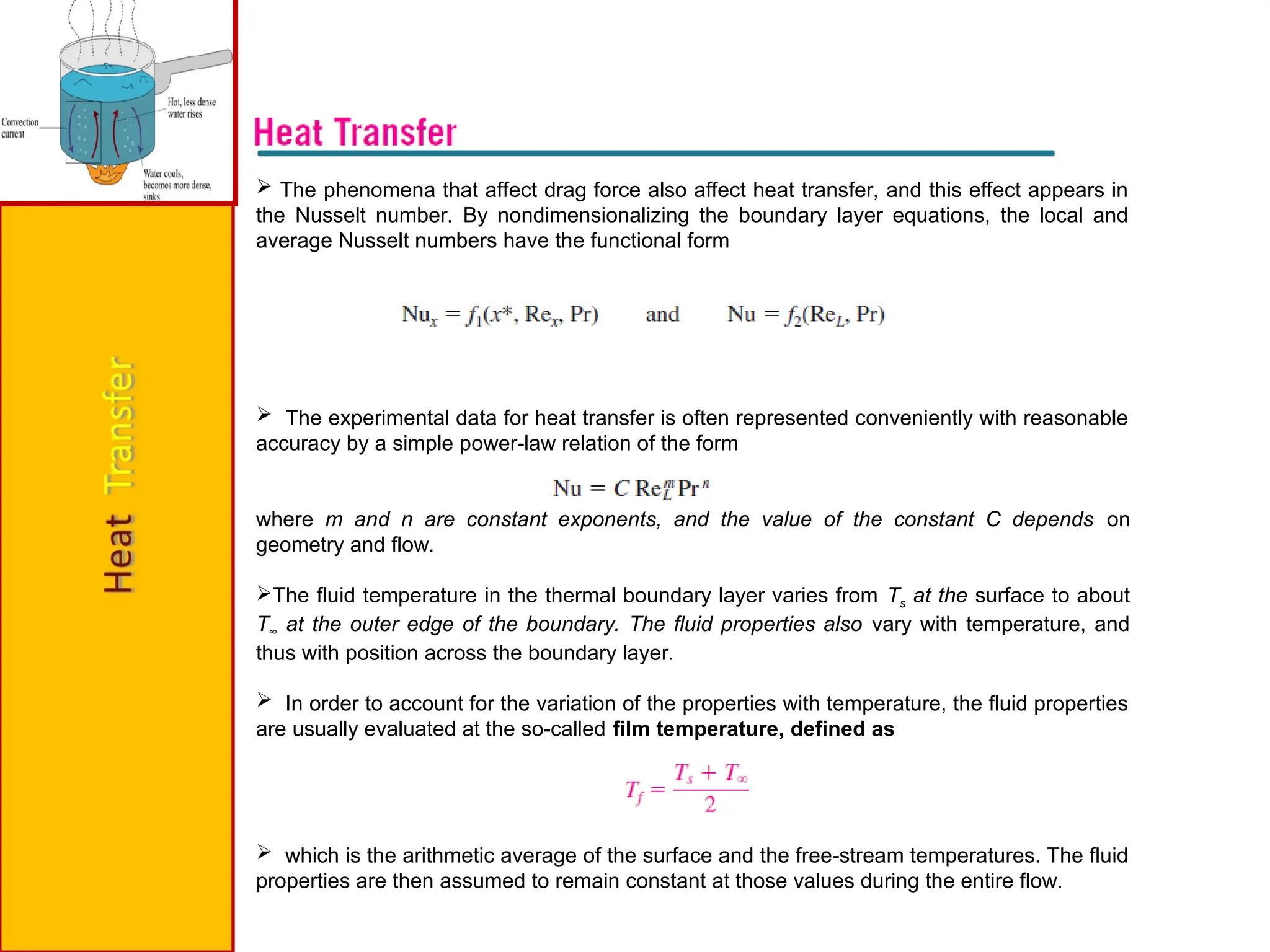
The phenomenathat affect drag force also affect heat transfer, and this effect appears in
the Nusselt number. By nondimensionalizing the boundary layer equations, the local and
average Nusselt numbers have the functional form
The experimental data for heat transfer is often represented conveniently with reasonable
accuracy by a simple power-law relation of the form
where m and n are constant exponents, and the value of the constant C depends on
geometry and flow.
The fluid temperature in the thermal boundary layer varies from Ts at the surface to about
T∞ at the outer edge of the boundary. The fluid properties also vary with temperature, and
thus with position across the boundary layer.
In order to account for the variation of the properties with temperature, the fluid properties
are usually evaluated at the so-called film temperature, defined as
which is the arithmetic average of the surface and the free-stream temperatures. The fluid
properties are then assumed to remain constant at those values during the entire flow.
19.
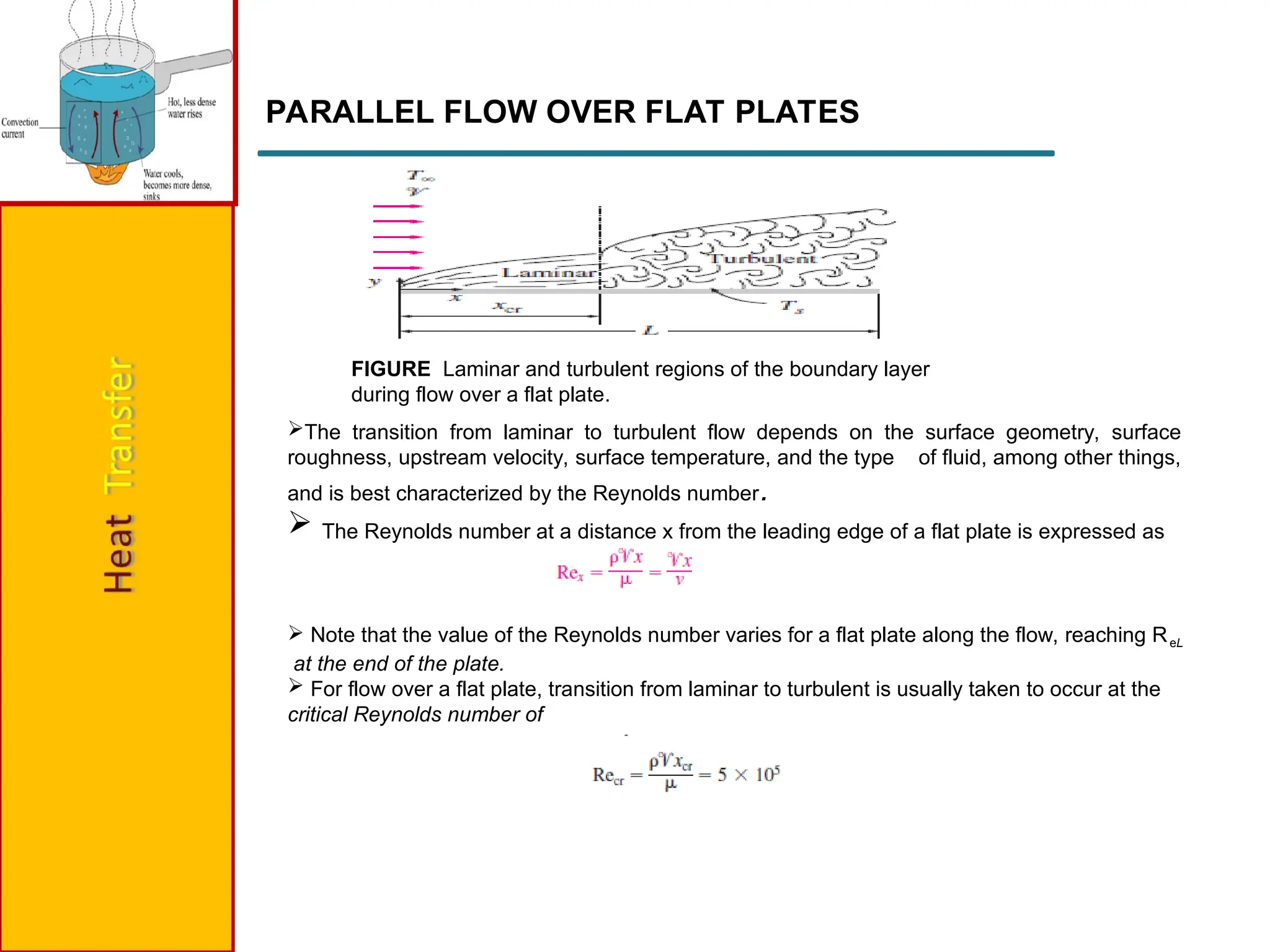
PARALLEL FLOW OVERFLAT PLATES
FIGURE Laminar and turbulent regions of the boundary layer
during flow over a flat plate.
The transition from laminar to turbulent flow depends on the surface geometry, surface
roughness, upstream velocity, surface temperature, and the type of fluid, among other things,
and is best characterized by the Reynolds number.
The Reynolds number at a distance x from the leading edge of a flat plate is expressed as
Note that the value of the Reynolds number varies for a flat plate along the flow, reaching ReL
at the end of the plate.
For flow over a flat plate, transition from laminar to turbulent is usually taken to occur at the
critical Reynolds number of
20.
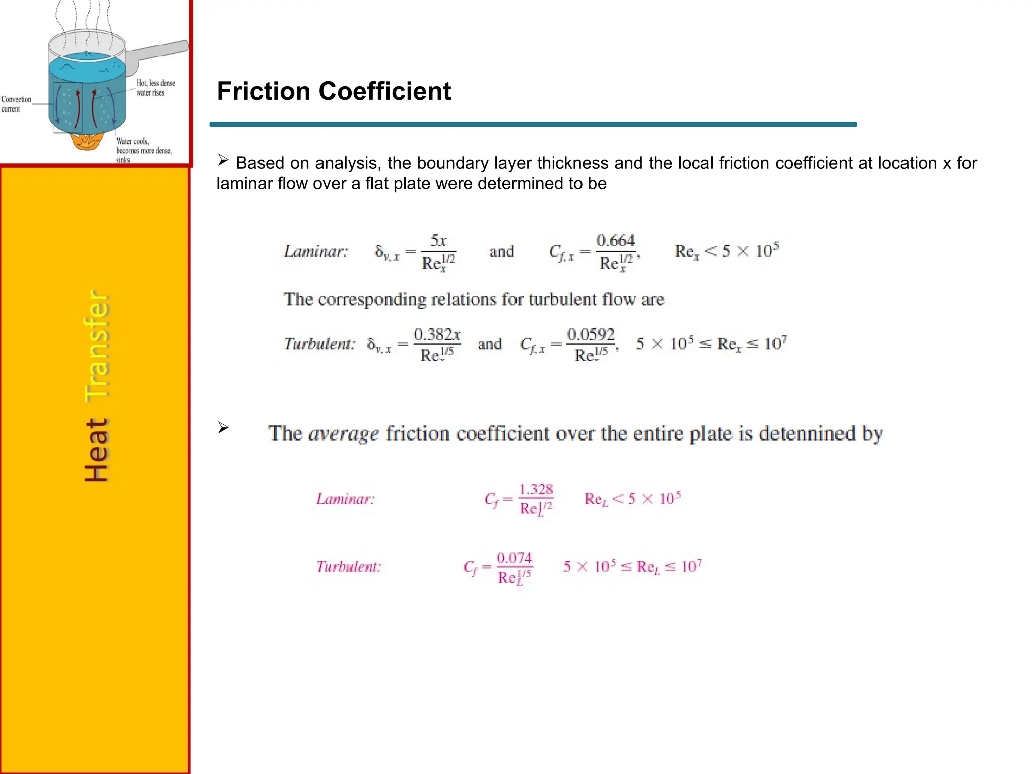
Friction Coefficient
Basedon analysis, the boundary layer thickness and the local friction coefficient at location x for
laminar flow over a flat plate were determined to be
21.
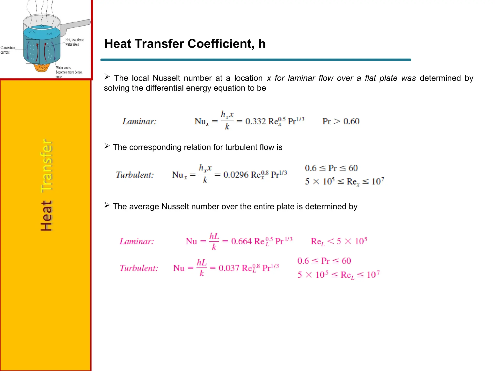
Heat Transfer Coefficient,h
The local Nusselt number at a location x for laminar flow over a flat plate was determined by
solving the differential energy equation to be
The corresponding relation for turbulent flow is
The average Nusselt number over the entire plate is determined by
22.
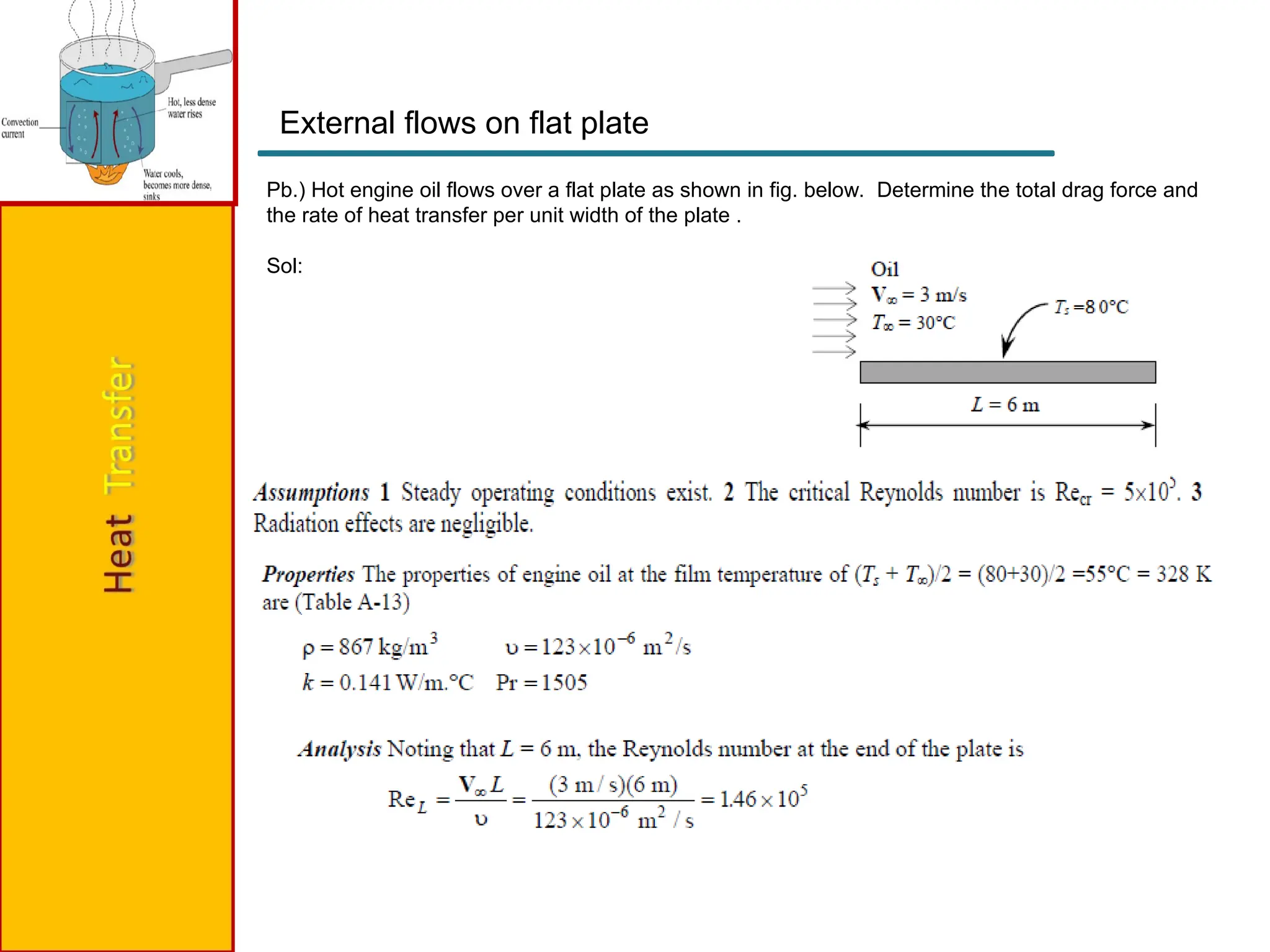
Pb.) Hot engineoil flows over a flat plate as shown in fig. below. Determine the total drag force and
the rate of heat transfer per unit width of the plate .
Sol:
External flows on flat plate
24.
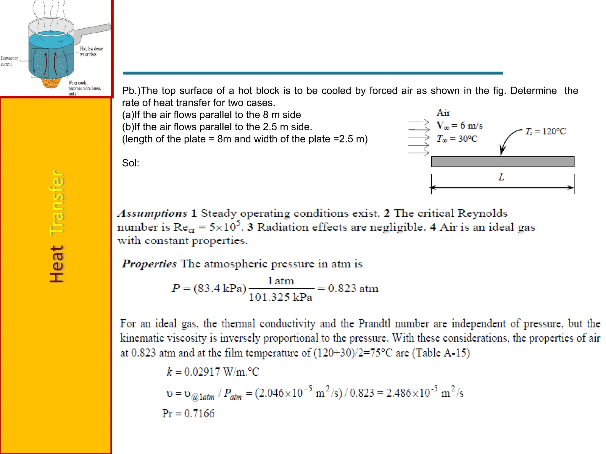
Pb.)The top surfaceof a hot block is to be cooled by forced air as shown in the fig. Determine the
rate of heat transfer for two cases.
(a)If the air flows parallel to the 8 m side
(b)If the air flows parallel to the 2.5 m side.
(length of the plate = 8m and width of the plate =2.5 m)
Sol:
29.
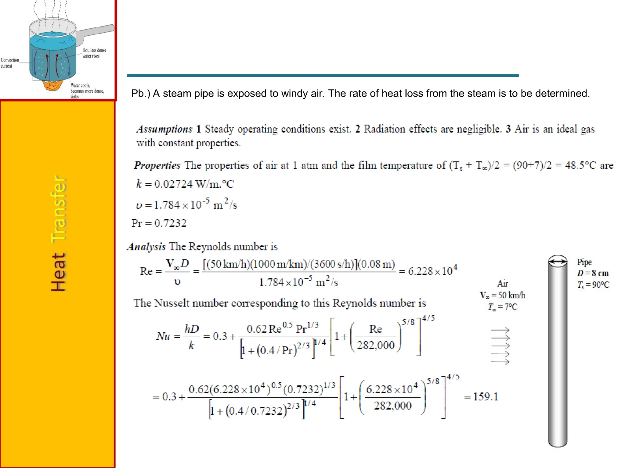
Pb.) A steampipe is exposed to windy air. The rate of heat loss from the steam is to be determined.
Contents
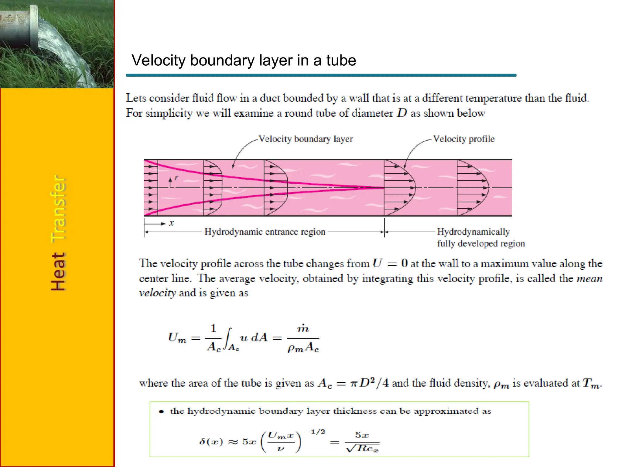
Concepts ofhydrodynamic and thermal boundary layer
Use of empirical relations for horizontal and annulus pipe flow
33.
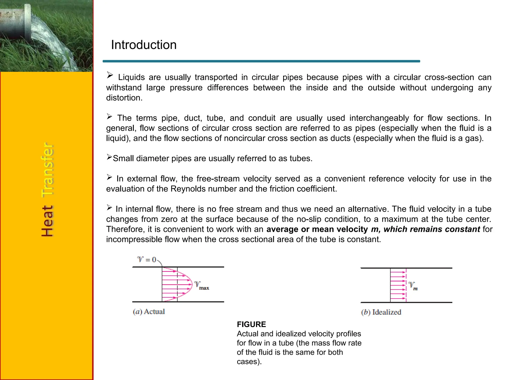
Liquids areusually transported in circular pipes because pipes with a circular cross-section can
withstand large pressure differences between the inside and the outside without undergoing any
distortion.
The terms pipe, duct, tube, and conduit are usually used interchangeably for flow sections. In
general, flow sections of circular cross section are referred to as pipes (especially when the fluid is a
liquid), and the flow sections of noncircular cross section as ducts (especially when the fluid is a gas).
Small diameter pipes are usually referred to as tubes.
In external flow, the free-stream velocity served as a convenient reference velocity for use in the
evaluation of the Reynolds number and the friction coefficient.
In internal flow, there is no free stream and thus we need an alternative. The fluid velocity in a tube
changes from zero at the surface because of the no-slip condition, to a maximum at the tube center.
Therefore, it is convenient to work with an average or mean velocity m, which remains constant for
incompressible flow when the cross sectional area of the tube is constant.
FIGURE
Actual and idealized velocity profiles
for flow in a tube (the mass flow rate
of the fluid is the same for both
cases).
Introduction
34.
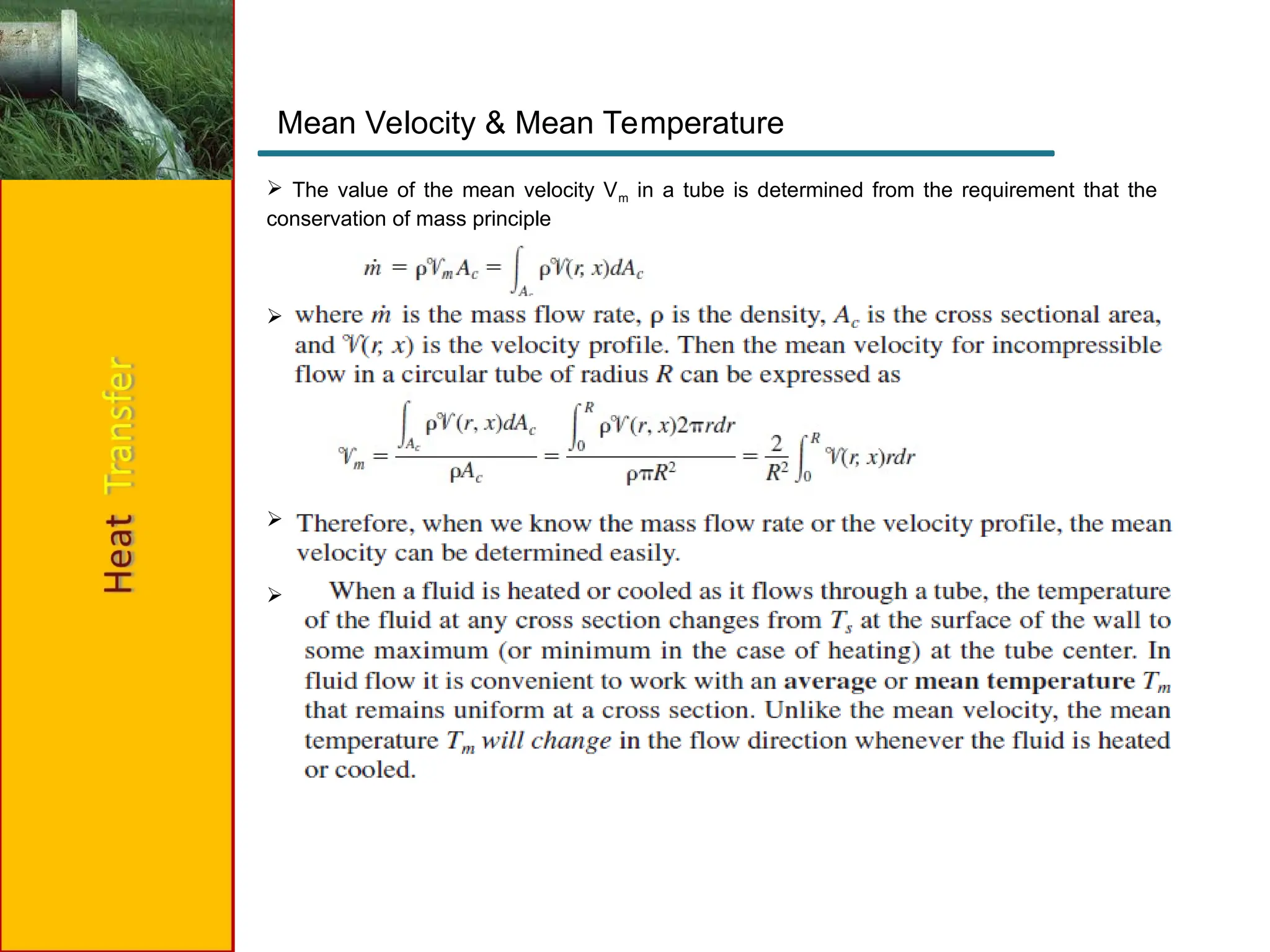
The valueof the mean velocity Vm in a tube is determined from the requirement that the
conservation of mass principle
Mean Velocity & Mean Temperature
35.
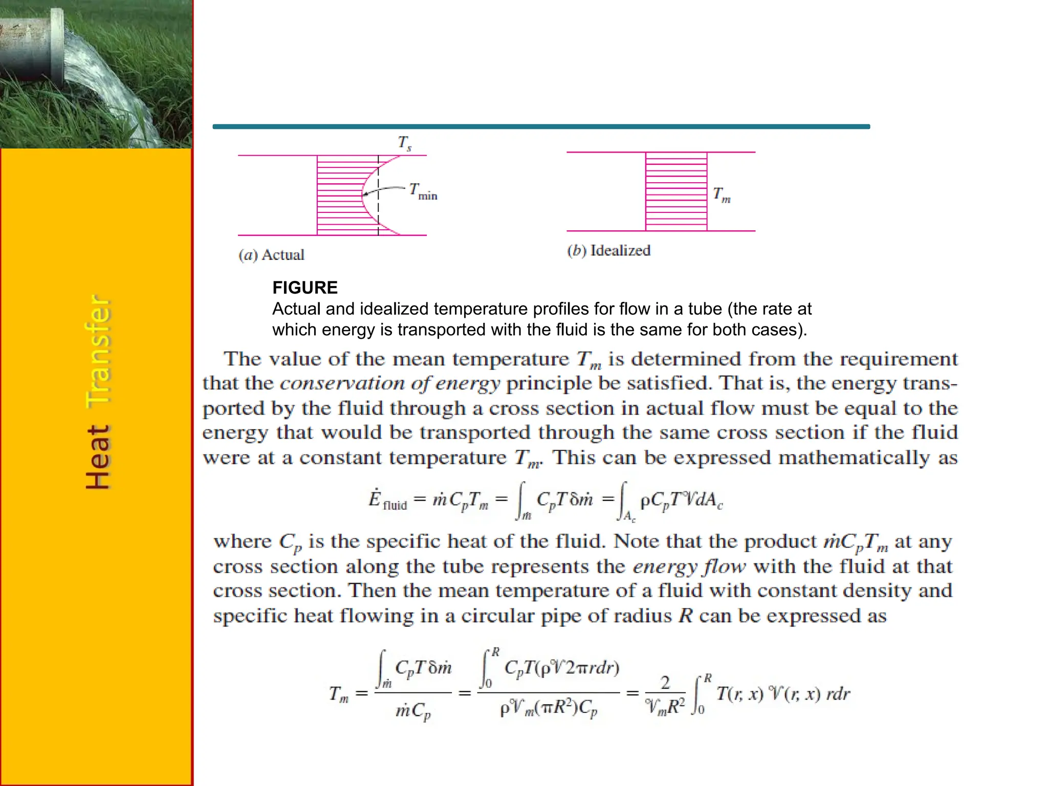
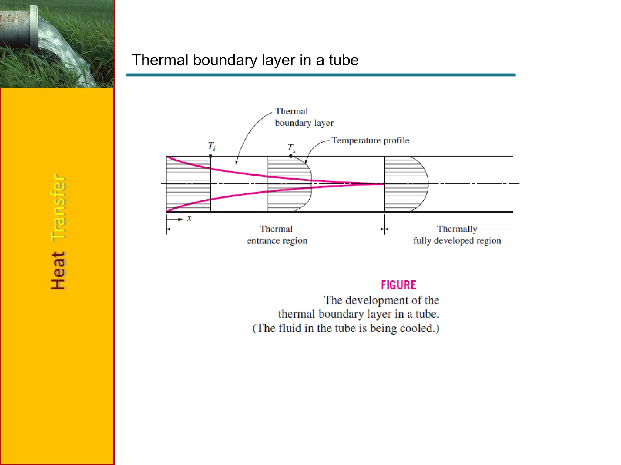
FIGURE
Actual and idealizedtemperature profiles for flow in a tube (the rate at
which energy is transported with the fluid is the same for both cases).
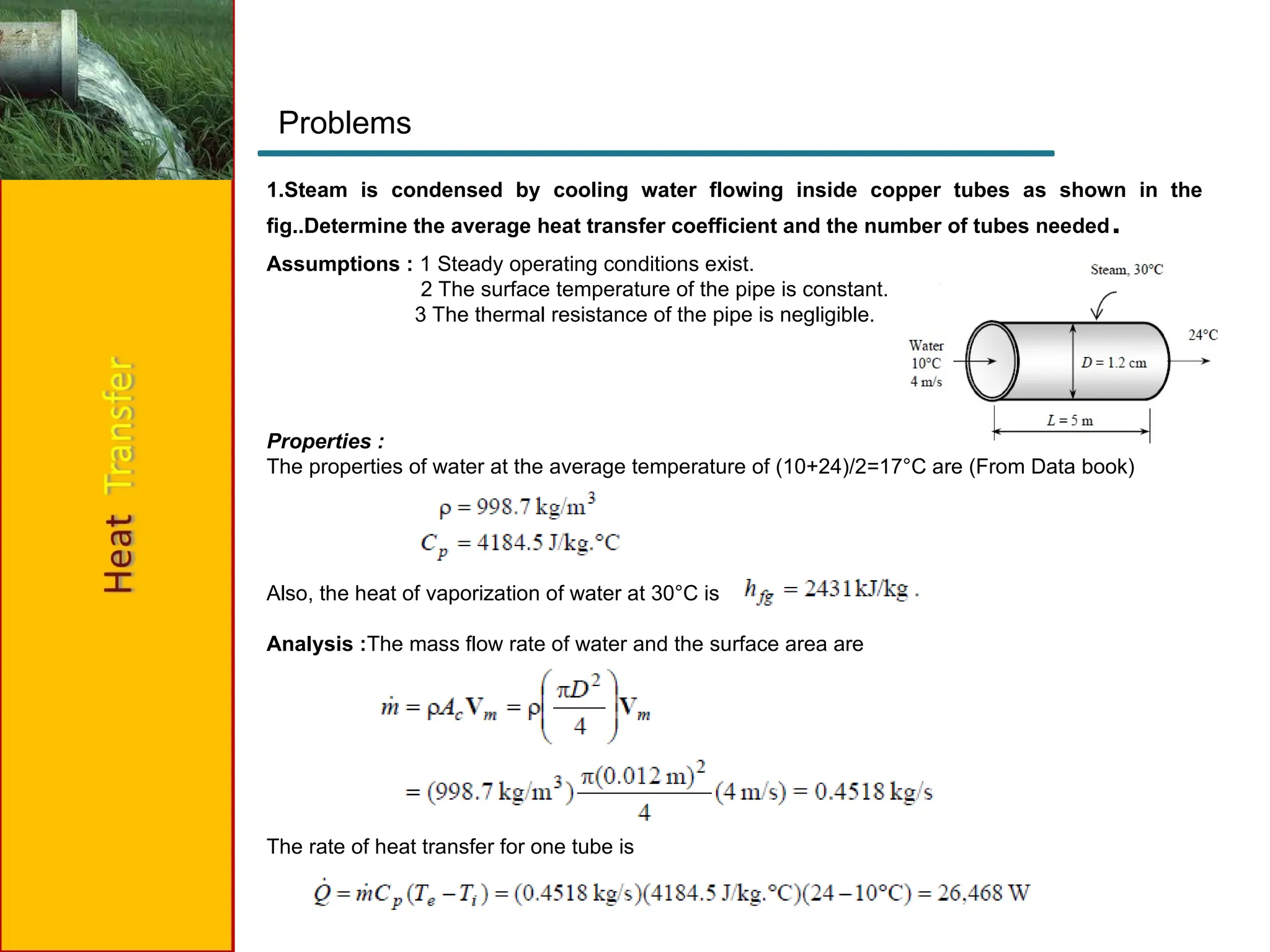
1.Steam is condensedby cooling water flowing inside copper tubes as shown in the
fig..Determine the average heat transfer coefficient and the number of tubes needed.
Problems
Assumptions : 1 Steady operating conditions exist.
2 The surface temperature of the pipe is constant.
3 The thermal resistance of the pipe is negligible.
Properties :
The properties of water at the average temperature of (10+24)/2=17°C are (From Data book)
Also, the heat of vaporization of water at 30°C is
Analysis :The mass flow rate of water and the surface area are
The rate of heat transfer for one tube is
43.
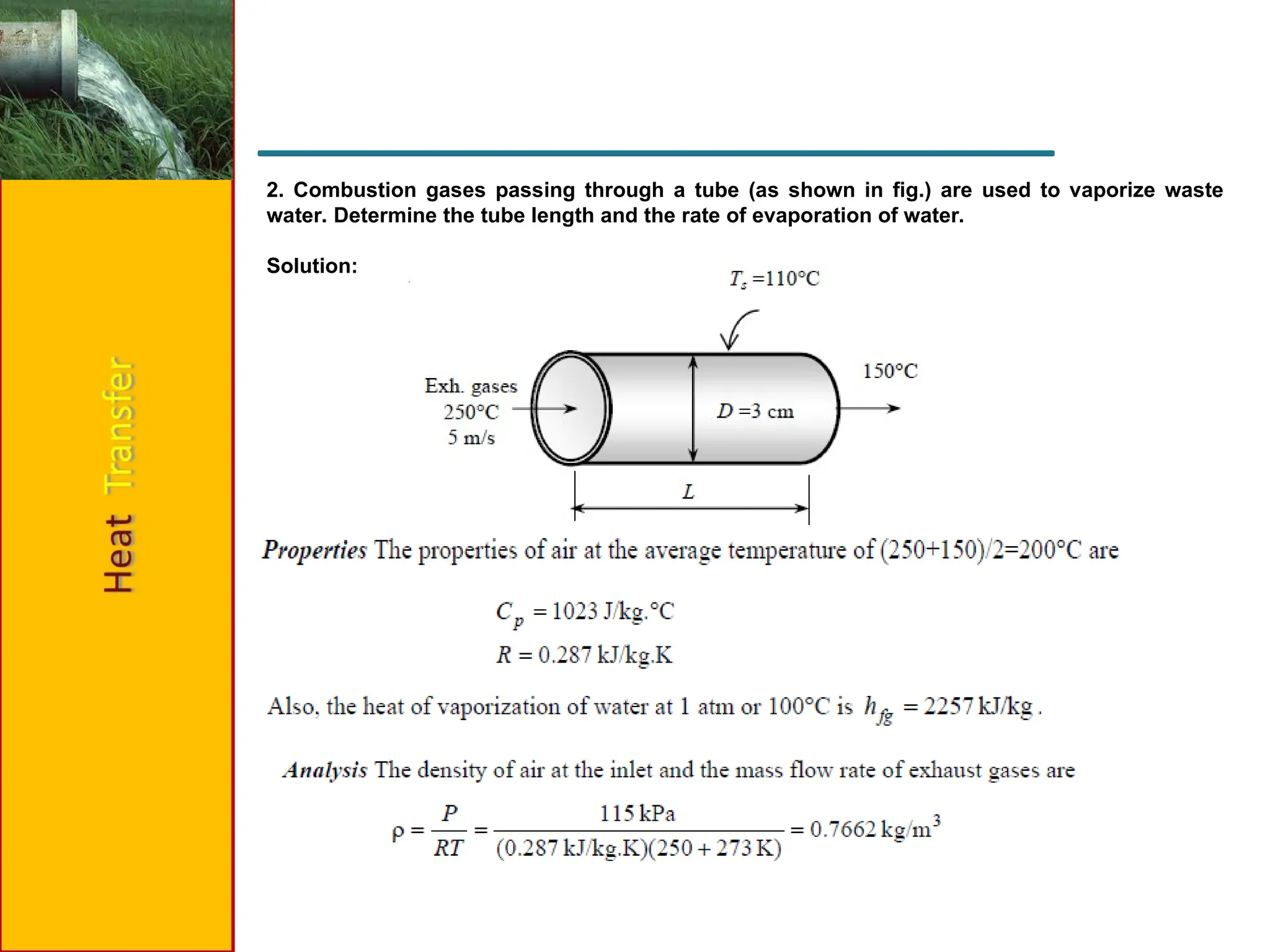
2. Combustion gasespassing through a tube (as shown in fig.) are used to vaporize waste
water. Determine the tube length and the rate of evaporation of water.
Solution:
46.
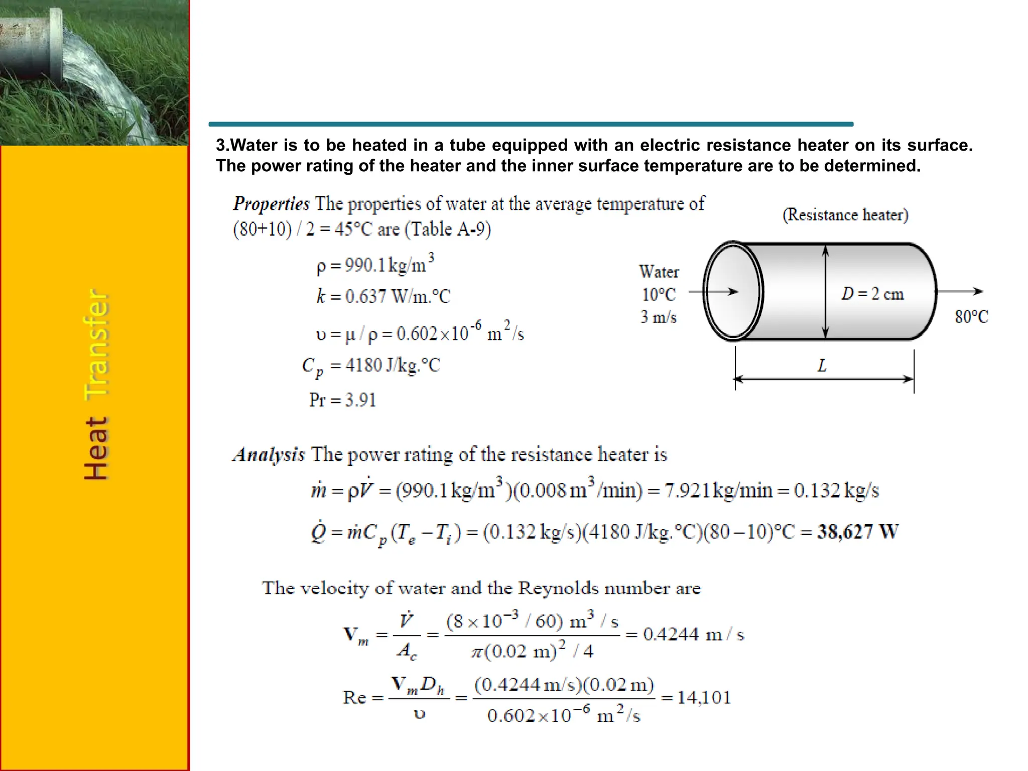
3.Water is tobe heated in a tube equipped with an electric resistance heater on its surface.
The power rating of the heater and the inner surface temperature are to be determined.
48.
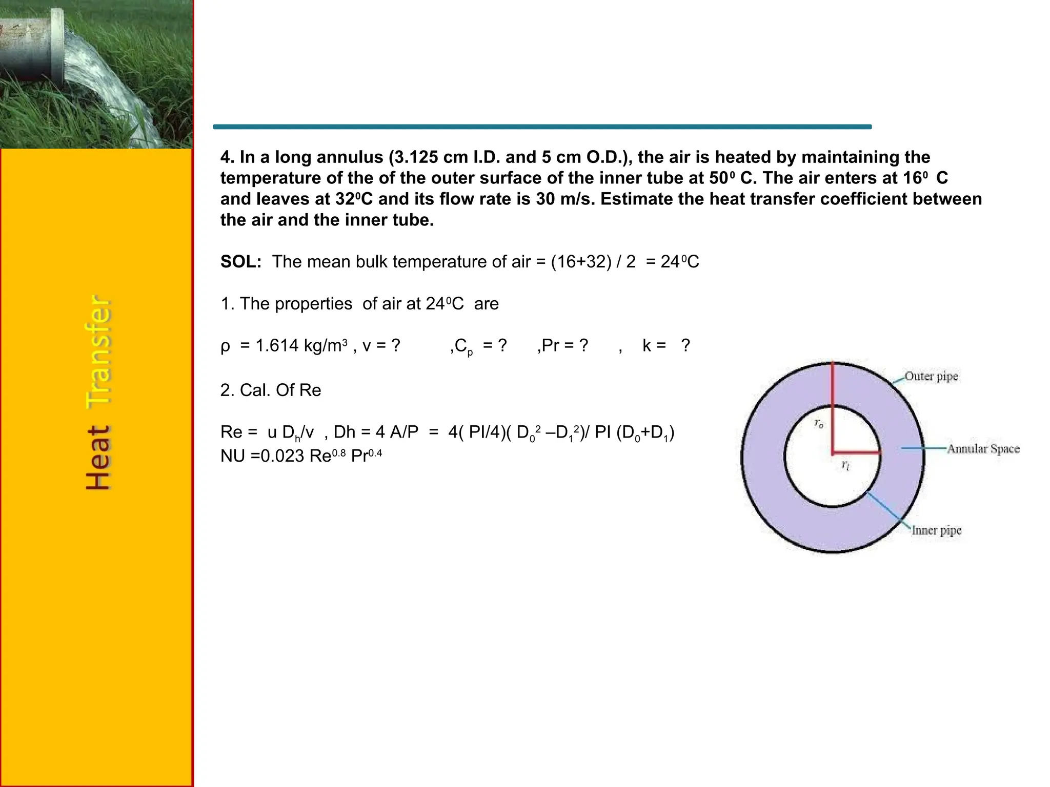
4. In along annulus (3.125 cm I.D. and 5 cm O.D.), the air is heated by maintaining the
temperature of the of the outer surface of the inner tube at 500
C. The air enters at 160
C
and leaves at 320
C and its flow rate is 30 m/s. Estimate the heat transfer coefficient between
the air and the inner tube.
SOL: The mean bulk temperature of air = (16+32) / 2 = 240
C
1. The properties of air at 240
C are
ρ = 1.614 kg/m3
, ν = ? ,Cp = ? ,Pr = ? , k = ?
2. Cal. Of Re
Re = u Dh/v , Dh = 4 A/P = 4( PI/4)( D0
2
–D1
2
)/ PI (D0+D1)
NU =0.023 Re0.8
Pr0.4