![Arash Vakily For Presentation Only
Equiblirium of forces on lockout button ram is shown below:
Forces R1, R2 are result of deformation of the two lockout beams creating tactile feel
Forces f1, f2 are friction forces between the beams and the ram
Note: End float of the button pivot (along the width) allows the ram to self-adjust, creating equal forces on both sides.
Therefore, R1=R2=R and f1=f2=f
f
R Rx
Θ
Θ fx
Ry Θ
Y
F2
X
Θ
Θ
R
f
5 F2 = 2 Rx + 2 f x
6 f=µR
8 2 Ry = 2 Fv Returning force from deflection of the
9 Ry = Fv lockout beams on each of two sides
10 Ry = R Cos θ
R y = Fv
11 R = Fv / Cos θ ( 9 , 10 )
12 f = µ Fv / Cos θ (6)
13 fx = f Cos θ
14 fx = µ Fv Cos θ / Cos θ ( 6 , 13)
15 fx = µ Fv ( 14 )
16 Rx = R Sin θ
17 Rx = Ry Tan θ ( 10 , 16 ) Fv
18 F2 = 2 ( Rx + fx ) (5)
19 F2 = 2 ( Ry Tan θ + µ Fv) ( 15 , 17 )
20 F2 = 2 Fv ( Tan θ + µ ) ( 9 , 19 )
21 Fv = F2 / [ 2 ( Tan θ + µ ) ] ( 20 )
Page 3](https://image.slidesharecdn.com/forcedisplacementgenerationcalculationbyarashvakily-12807062130511-phpapp01/75/Force-Displacement-Generation-Calculation-By-Arash-Vakily-3-2048.jpg)
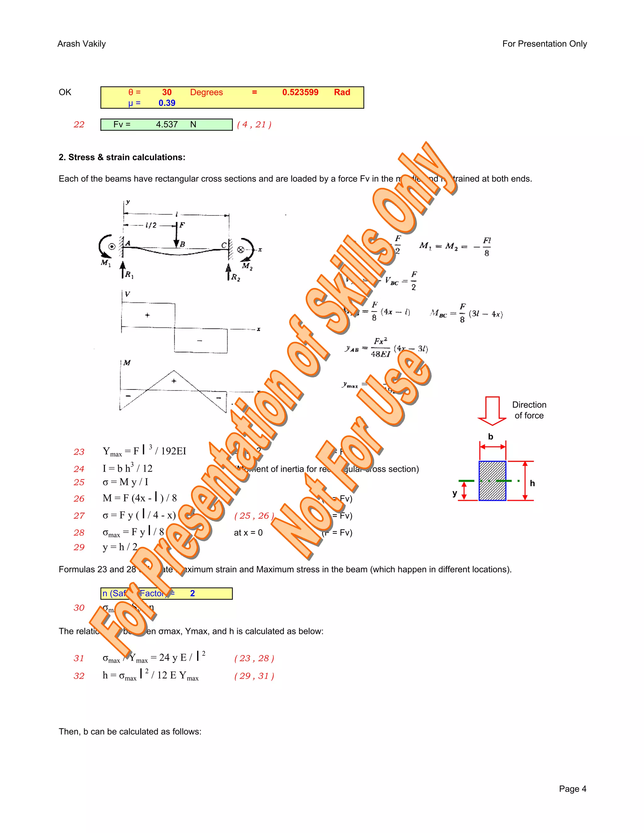
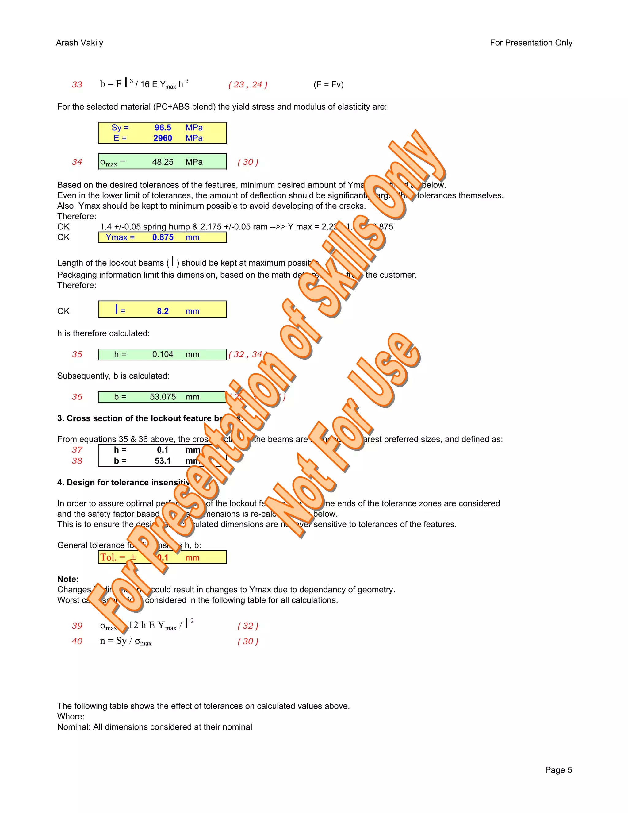


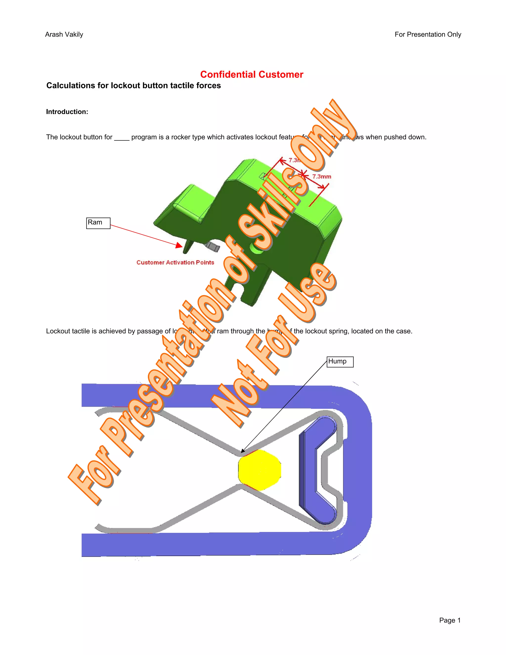
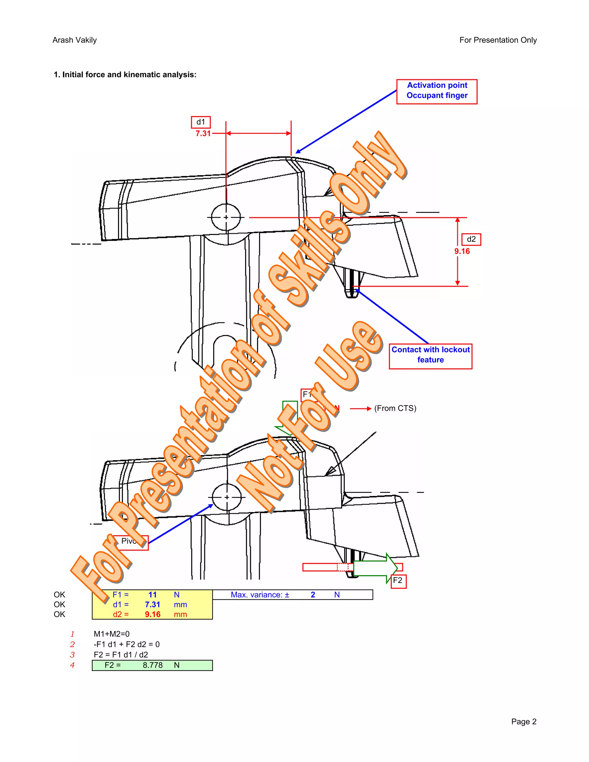
The document discusses the design calculations for the tactile force of a lockout button on a vehicle. It analyzes the kinematics and equilibrium of forces acting on the button and lockout spring. Key calculations determine: 1) The returning force Fv from the deflected lockout beams, which is related to the tactile force F2 felt by the user. 2) The stress and strain on the beams to ensure they do not yield. This relates the beam height h, length l, and maximum stress σmax. 3) The beam cross-section dimensions of h=0.1mm and b=53.1mm that satisfy the strength requirements. 4) A tolerance


