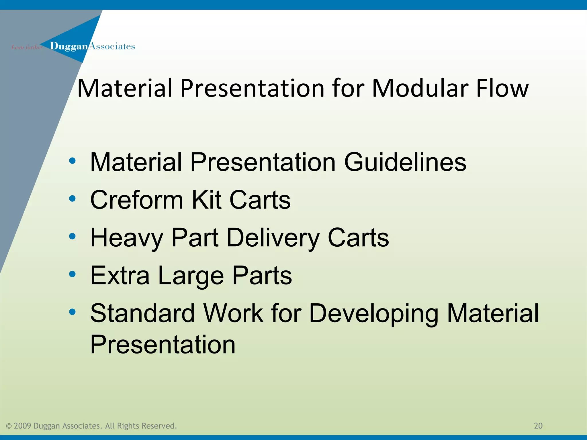
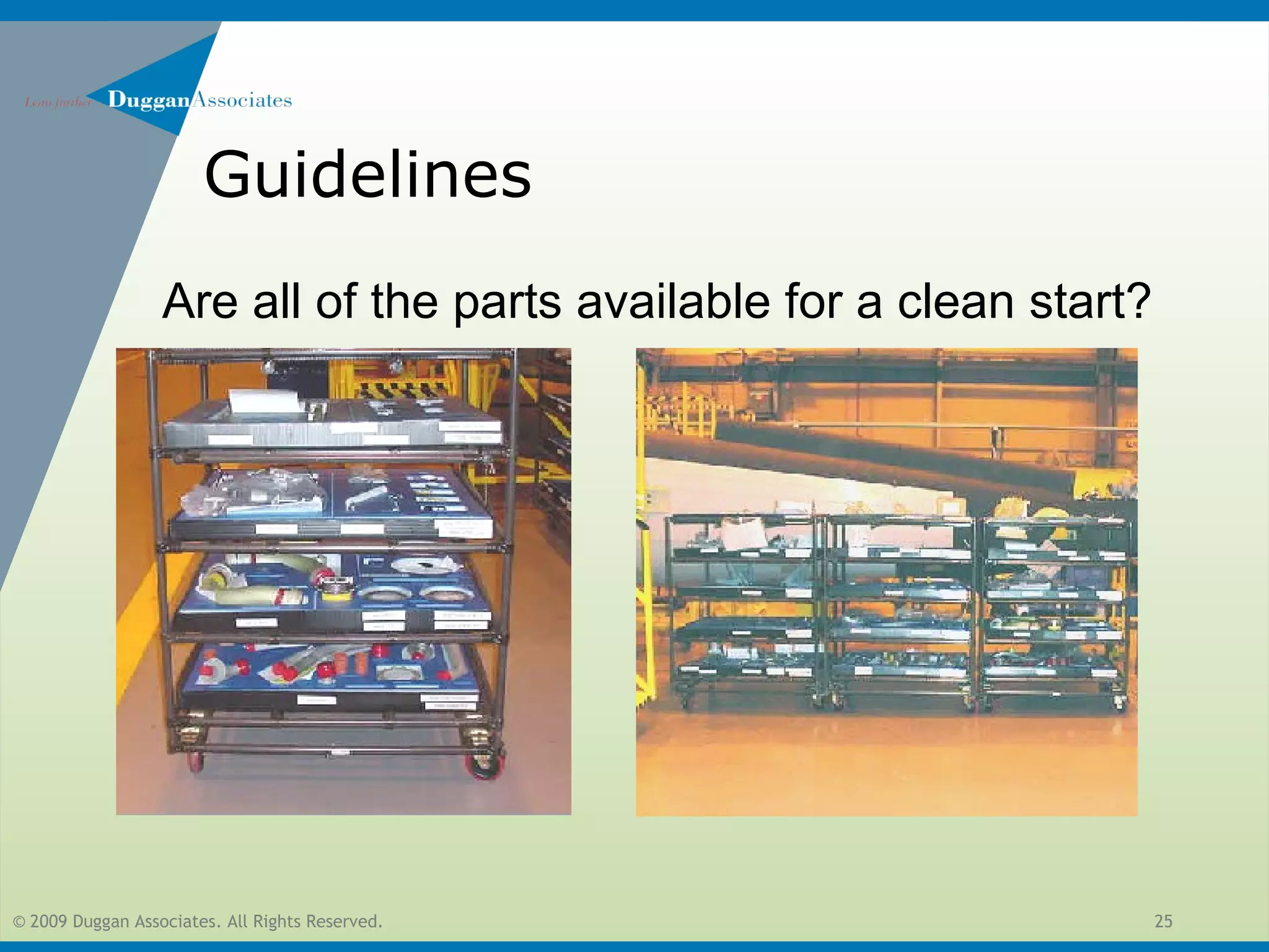
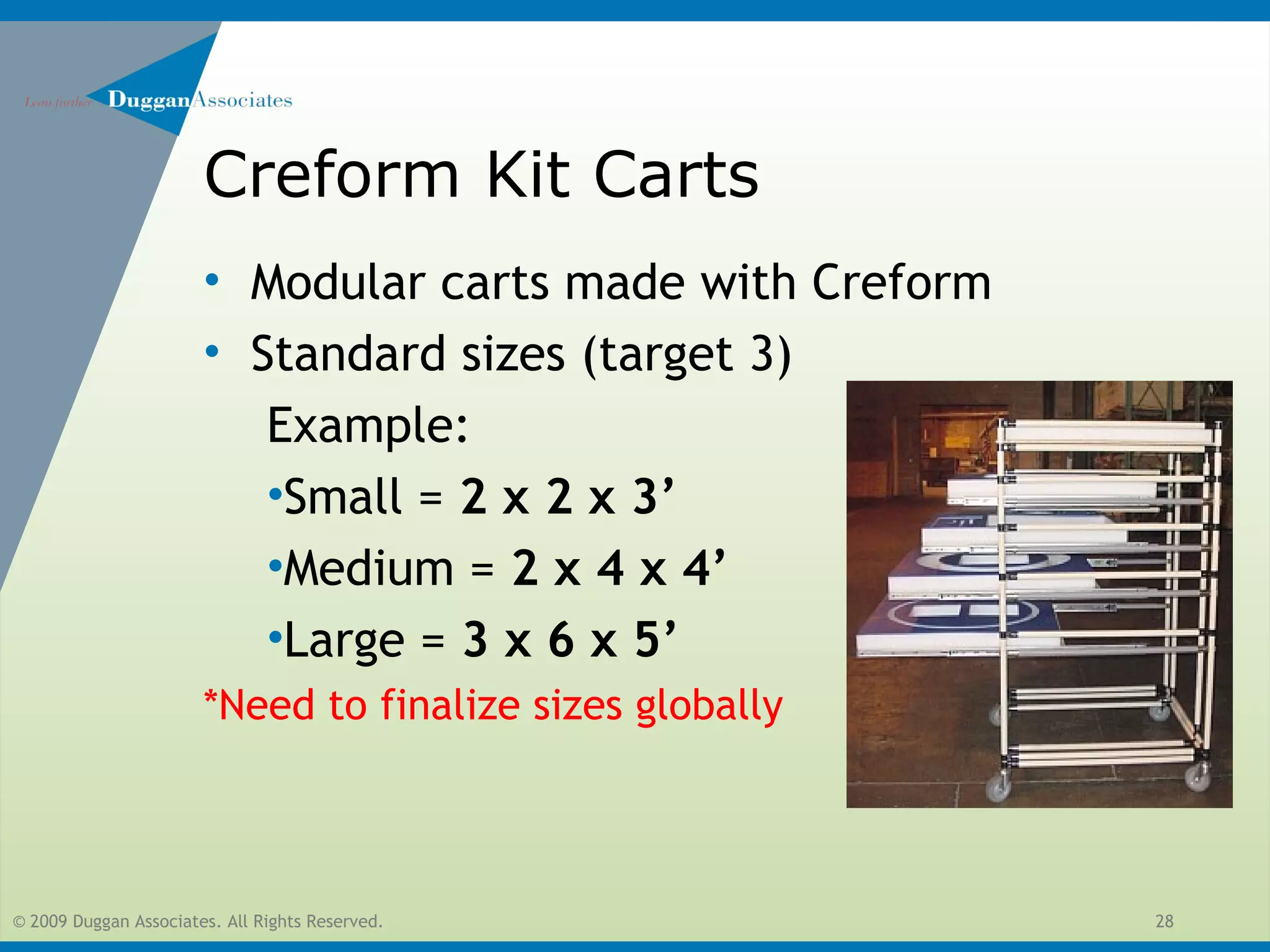
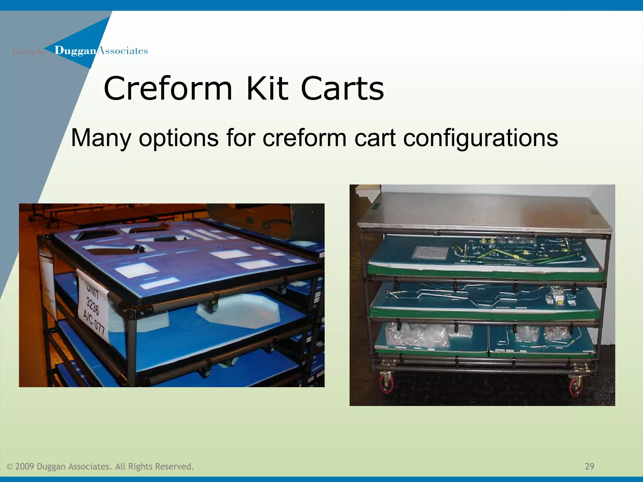
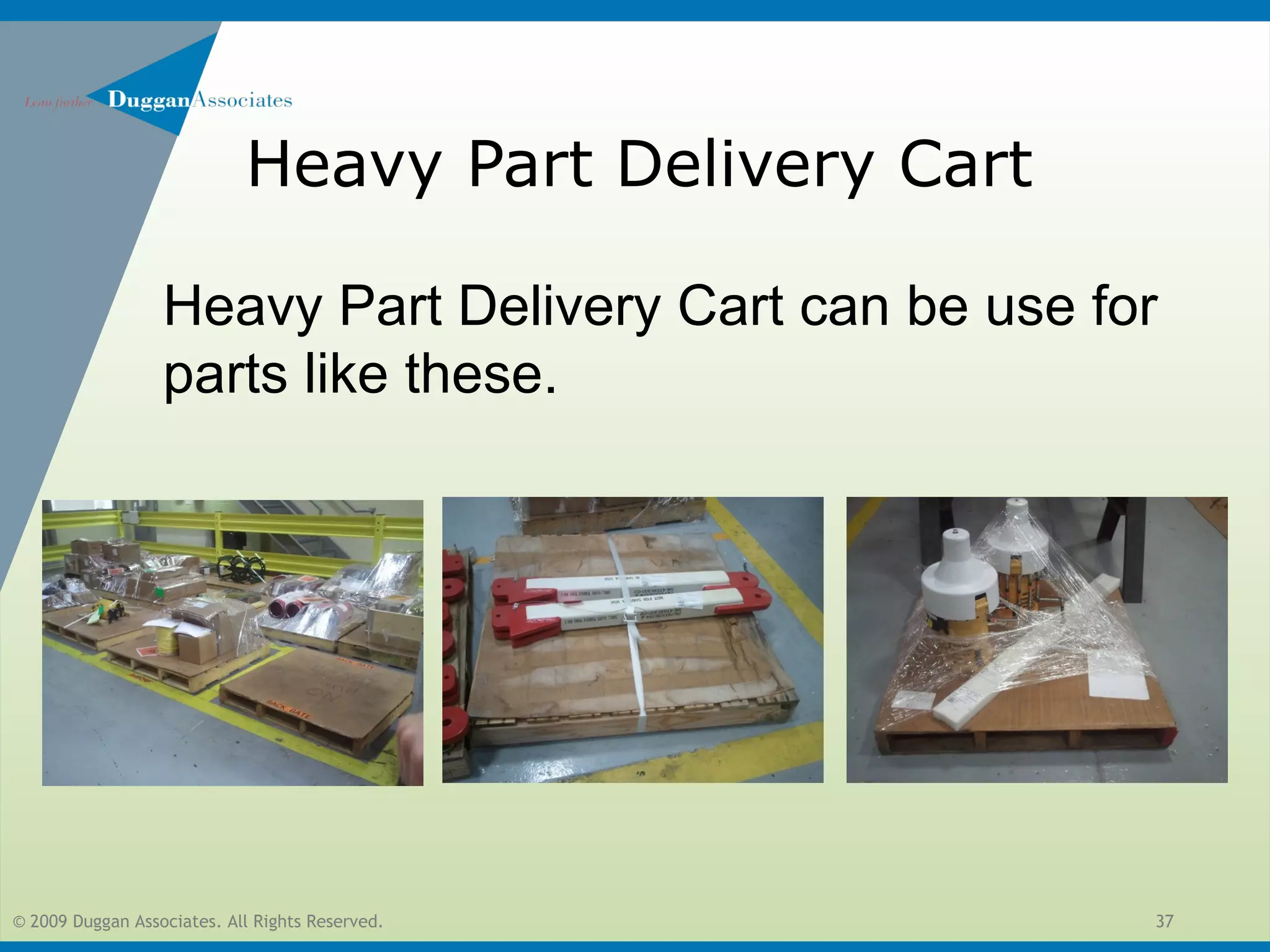
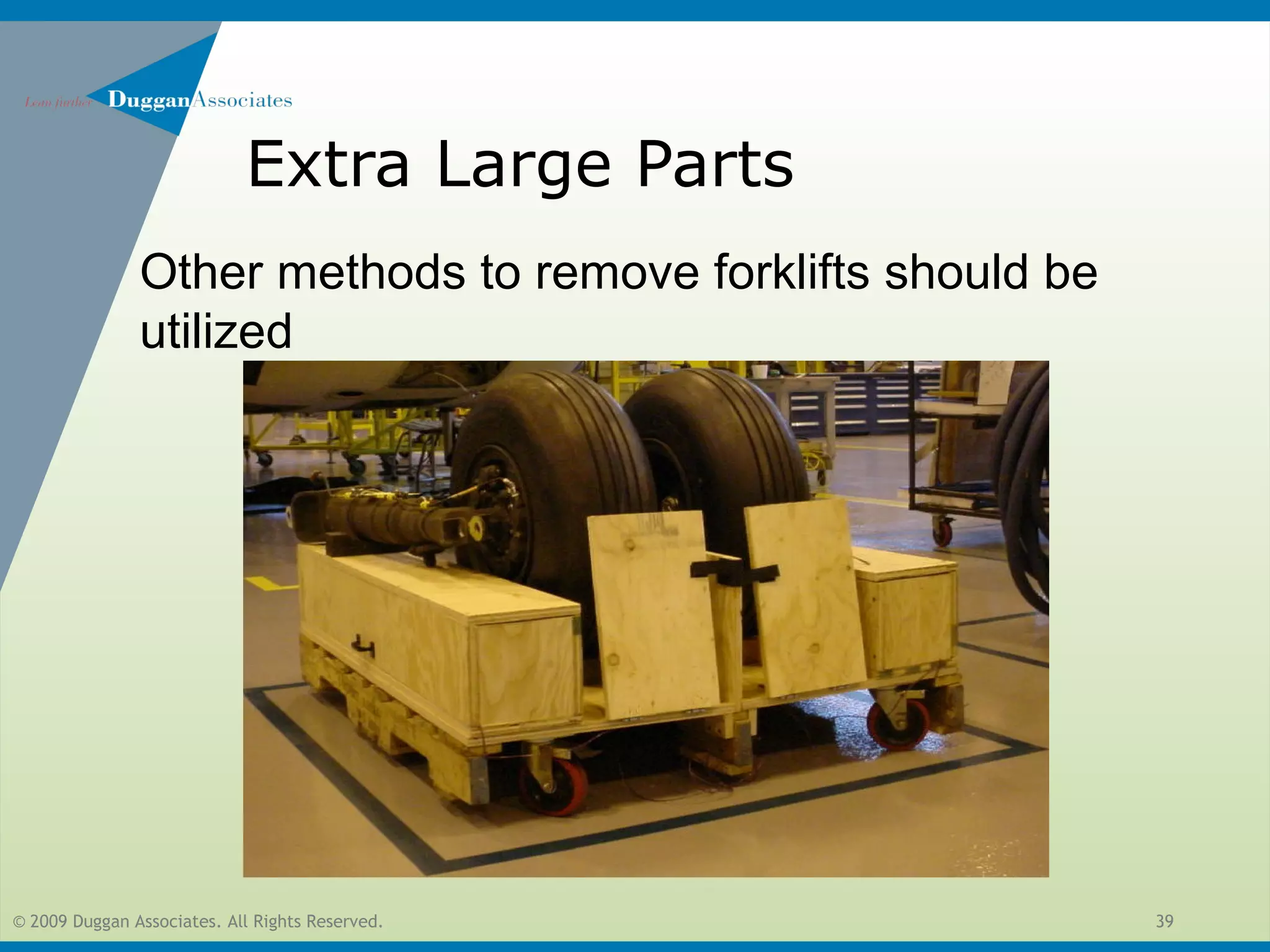
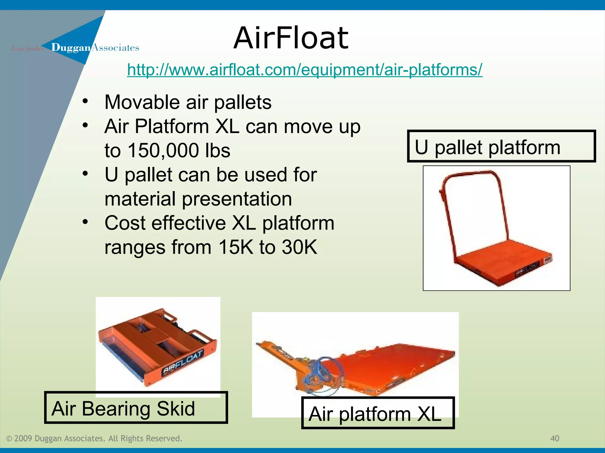
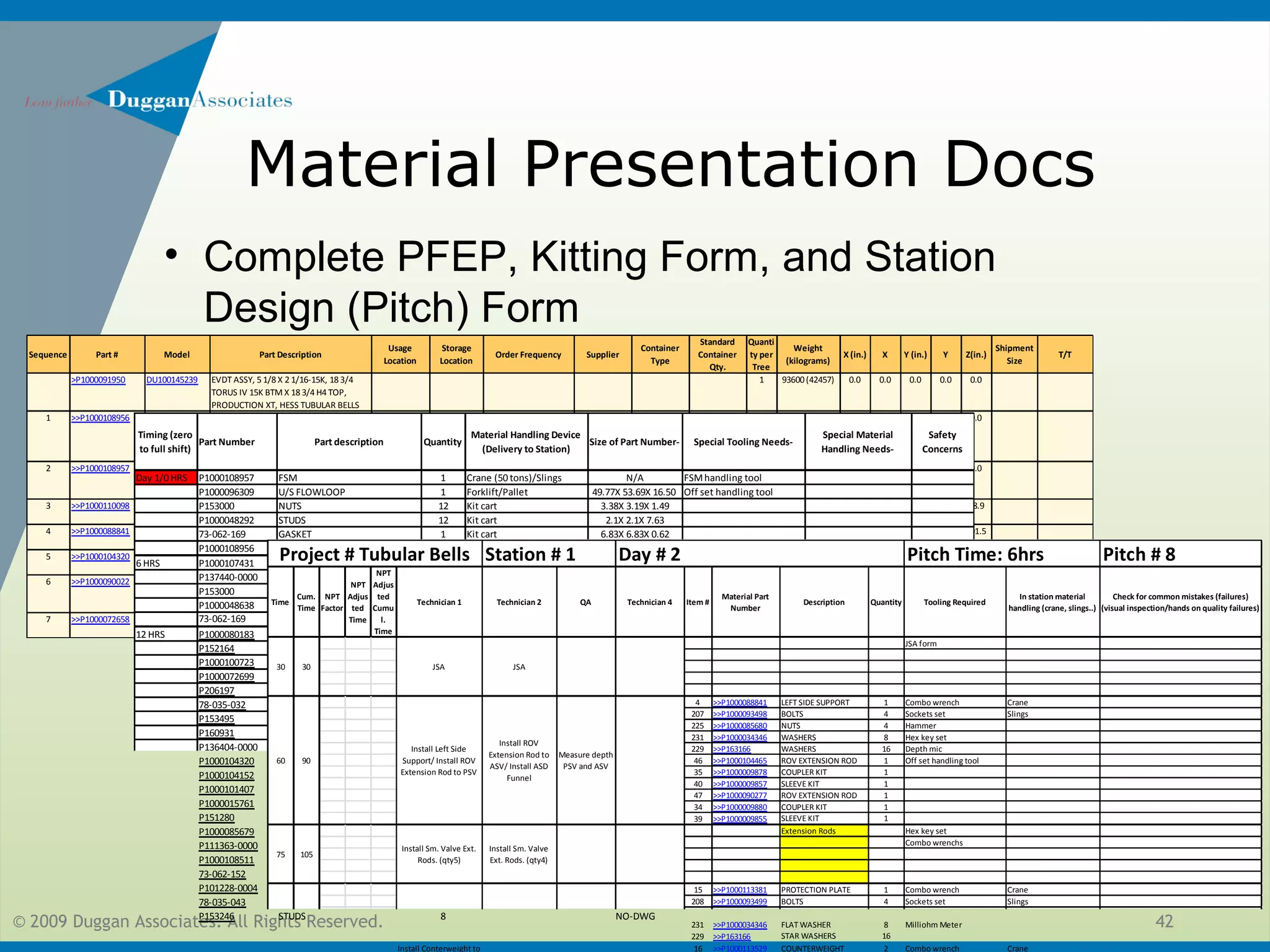
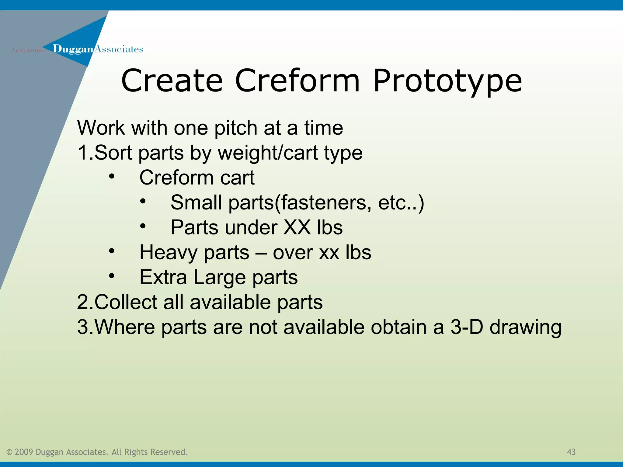
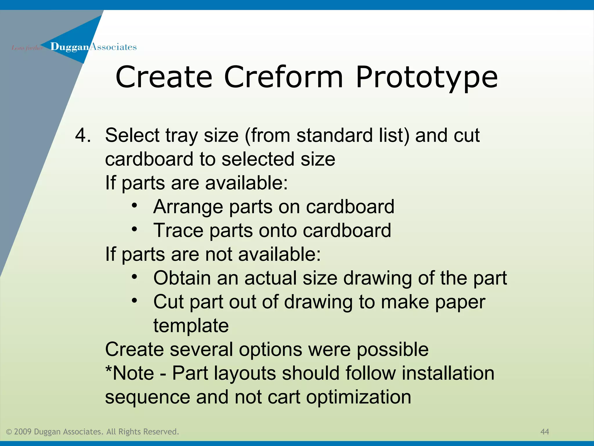
SlideShare a Scribd company logo
1 of 61
© 2009 Duggan Associates. All Rights Reserved. 1
FMC MODULAR FLOW
PRINCIPLES
Duggan Associates
www.dugganinc.com
08/03/2013
© 2009 Duggan Associates. All Rights Reserved. 2
• 20 Principles of Flow
• Foundations
• Safety
• TPM
• 5S
• Tooling Presentation
• Material Presentation
• Flow through High Bay
FMC MODULAR FLOW PRINCIPLES
© 2009 Duggan Associates. All Rights Reserved. 3
• 20 Principles of Flow
FMC MODULAR FLOW PRINCIPLES
© 2009 Duggan Associates. All Rights Reserved. 4
FMC Modular Flow Principles
Within each Workstation:
•No Safety violations
•No forklifts, no cranes, no hoists
•No trash containers in production areas
•No pits, no platforms
•No process flow reversals
•Mistake-proofing;
•Color coded go, no-go gages
•Everything must be less than 1.5 meters (5 feet) in height
•Visual Boards to show if station is on time
•Product and Operators do not leave the cell or line
•Daily equipment checks and TPM carried out routinely, no unplanned
equipment downtime that reduces available working time
•Quality issues are identified and addressed.
© 2009 Duggan Associates. All Rights Reserved. 5
FMC Modular Flow Principles
Across the Flow of High Bay:
11.One-Piece Tree Flow
12.Value Stream Map exists that show the new designed flow
13.Inspection processes upstream in modules
14.Modules built in parallel
15.Systems and Standard Work in place to prevent part shortages
16.Cross training is achieved; everyone can do everything, based upon
and know if they are on-time
17.Pitch used to pace the process
18.Visual Boards showing performance metrics
19.Plans for when flow breaks down
20.Management teaching and guiding on flow principles
© 2009 Duggan Associates. All Rights Reserved. 6
Foundations for Modular Flow
• Safety
• Non-Negotiable
• Health, Safety, Environment
• TPM
• 5S
© 2009 Duggan Associates. All Rights Reserved. 7
Non-Negotiable
Health, Safety, Environment
© 2009 Duggan Associates. All Rights Reserved. 8
Non-negotiable Safety Reqs.
•Fire extinguishers will be clearly marked by class (A, B, C) and
will meet NFPA standards. Extinguishers with gross weight not
exceeding 40 pounds should be installed so that the top of the
extinguisher is no more than five feet above the floor.
•Electrical breakouts will be clearly marked and have a 36” inch
clearance and be free of obstruction per OSHA guidelines
•Egress walkways will be free of obstruction and parking areas
for equipment and tooling and will be clearly marked.
•All flammable chemical cabinets will be grounded per 29 CFR
1910.106 and clearly marked with picture of cabinet contents
as well as FIFO system to avoid use of expired chemicals.
© 2009 Duggan Associates. All Rights Reserved. 9
Non-Negotiable
• Fire extinguishers will be clearly marked by class (A, B, C)
and will meet NFPA standards. Extinguishers with gross
weight not exceeding 40 pounds should be installed so that
the top of the extinguisher is no more than five feet above
the floor.
© 2009 Duggan Associates. All Rights Reserved. 10
HAZMAT Control/ Chemical
HandlingVisual Coding of
expiration
Type/MSDS info and
expiration are clearly marked
© 2009 Duggan Associates. All Rights Reserved. 11
Chemical Cabinet 5S
• Chemical cabinet
should have picture of
contents and display
proper and in-proper
condition
© 2009 Duggan Associates. All Rights Reserved. 12
TPM
© 2009 Duggan Associates. All Rights Reserved. 13
PPE & TPM Requirements listed at each
Station
13
• PPE and TPM
requirements
are listed at
every
workstation
© 2009 Duggan Associates. All Rights Reserved. 14
Visual Gauge markings
14
Gauge Highlighting:
Red - failure mode
Yellow – warning/execute control plan
Green - normal
© 2009 Duggan Associates. All Rights Reserved. 15
VISUAL STANDARD
ATTRIBUTES OF VISUAL
Identify Pipes at Key Locations Only
Highlight Processes, not Facilities.
Pipe Labels are “Snap-on” Collars:
Supplier Grainger item # 6GT35
Color Code Based upon ASME A13.1 –
2007 US Piping Identification Standards
15
Pipe Labeling
Material
Backgrou
nd Color
Legend
Letter
Color
Background
Color and
Letter Sample
Fire quenching (water, foam, CO2,
etc)
Red White LEGEND
Toxic and corrosive Black LEGEND
Flammable Yellow Black LEGEND
Combustible Brown White LEGEND
Water (potable, boiler feed, cooling,
etc)
Green White
LEGEND
Compressed air Blue White LEGEND
Defined by site (for other materials
not listed)
Purple White
LEGEND
Defined by site (for other materials
not listed)
White Black
LEGEND
Defined by site (for other materials
not listed)
Gray White
LEGEND
Defined by site (for other materials
not listed)
Black White
LEGEND
ND
LEGENDLEGEND
LEGEND
Label at line of sight
© 2009 Duggan Associates. All Rights Reserved. 16
5S FOR FLOW
BLUE Work in Process
YELLOW Main Aisles, General Areas, Cart Parking Areas
YELLOW / BLACK Machine Guarding
RED Electrical Shutoffs/ Fire Protection/ Defective Material
GREEN Final WorkStation
ORANGE Moving Crane Parts, Compressed Gas Racks
Visual Factory Guidelines
© 2009 Duggan Associates. All Rights Reserved. 18
VISUAL standard
ATTRIBUTES OF VISUAL
Solid Lines or Corners for
Floor Markings
18
Floor Marking
EH&S, Non/Hazardous Waste,
Non-conforming material
Incoming/Outgoing Product
(Raw or Finished Goods)
WIP in Work Cell
Main Aisle Borders
4” width
2” width
2” width
2” width
2” width
Cart Parking Location
Standard Corners
Floor Tape Specification: High-
Strength, Double-Coated Tape,
Removable Pressure Sensitive
Rubber-Based Adhesive. Source:
WWW.Mightyline Store.com
Note: Standard colors for manufacturing areas
© 2009 Duggan Associates. All Rights Reserved. 19
Material Presentation for Modular
Flow
© 2009 Duggan Associates. All Rights Reserved. 20
• Material Presentation Guidelines
• Creform Kit Carts
• Heavy Part Delivery Carts
• Extra Large Parts
• Standard Work for Developing Material
Presentation
Material Presentation for Modular Flow
© 2009 Duggan Associates. All Rights Reserved. 21
• Material Presentation Guidelines
• Creform Kit Carts
• Heavy Part Delivery Carts
• Extra Large Parts
• Standard Work for Developing Material
Presentation
Material Presentation for Modular Flow
© 2009 Duggan Associates. All Rights Reserved. 22
Guidelines
• Forklifts and cranes restrict flow. Eliminate the use of forklifts and cranes for
material delivery to the cell and material handling in the cell as much as
possible.
• Forklifts should never enter the station. If forklift delivery is required, it should
be at the front of the station
• Searching for a part should never happen
• No unpacking/opening boxes/searching through containers should happen at
station
• No carts over 5 ft, as it will block operator view
© 2009 Duggan Associates. All Rights Reserved. 23
Guidelines
• Material Presentation is designed in advance not arrange while working
• Parts should be presented to technicians similar to a surgeon in an operating room
• Material availability should be so ‘transparent’ that a visitor should be able to tell if all of the
parts needed are present
• We should be able to easily tell if we have a clean start
• Each part should have a dedicated and easily identifiable location and usage
• Maximize use of material carts (one person can move without any material handling devices)
where safety is not compromised
• Material should be delivered at preset time (pitch). The target time should be half of a shift
with a maximum of one shift.
© 2009 Duggan Associates. All Rights Reserved. 24
Guidelines
Are all of the parts available for a clean start?
© 2009 Duggan Associates. All Rights Reserved. 25
Guidelines
Are all of the parts available for a clean start?
© 2009 Duggan Associates. All Rights Reserved. 26
• Material Presentation Guidelines
• Creform Kit Carts
• Heavy Part Delivery Carts
• Extra Large Parts
• Standard Work for Developing Material
Presentation
Material Presentation for Modular Flow
© 2009 Duggan Associates. All Rights Reserved. 27
Material Presentation Carts
In order to eliminate the use of cranes and
pallets and to provide point of use parts to
operator with no unpacking or waste generation
as much as possible parts will be presented to
the operators on carts.
Two type of carts: Creform cart and Heavy Part
Delivery cart
•*Under XX lbs use Creform kit carts
•*Over XX lbs use heavy part delivery cart (need
name for this cart)
*Need to finalize sizes globally
© 2009 Duggan Associates. All Rights Reserved. 28
Creform Kit Carts
• Modular carts made with Creform
• Standard sizes (target 3)
Example:
•Small = 2 x 2 x 3’
•Medium = 2 x 4 x 4’
•Large = 3 x 6 x 5’
*Need to finalize sizes globally
© 2009 Duggan Associates. All Rights Reserved. 29
Creform Kit Carts
Many options for creform cart configurations
© 2009 Duggan Associates. All Rights Reserved. 30
Creform Kit Carts
• Parts shadowed for material
presentation
• Designated location for each part
• Missing parts are easily identifiable
Reference sites:
• http://plasticeng.com/
• http://www.youtube.com/watch?v=r8A7jPR72o4&feature=
© 2009 Duggan Associates. All Rights Reserved. 31
Creform Kit Carts
Small Parts
Standard method needed for small parts
commonly used
• Nuts/Washers => Size specific
rods??
• Shafts => PVC tubes?
• Bolts => Containers ??
Right quantity must be easily visible
© 2009 Duggan Associates. All Rights Reserved. 32
• Material Presentation Guidelines
• Creform Kit Carts
• Heavy Part Delivery Carts
• Extra Large Parts
• Standard Work for Developing Material
Presentation
Material Presentation for Modular Flow
© 2009 Duggan Associates. All Rights Reserved. 33
Heavy Part Delivery Cart
Heavy parts (>XXlbs or >X’xX’)
• Universal base
• Heavy duty/stable
• Single person can move it
• Multiconfigurable for different
parts/projects
© 2009 Duggan Associates. All Rights Reserved. 34
Heavy Part Delivery Cart
After some design work heavy duty universal
base accepts custom tops
Update with liftup red top
and label 3 parts
© 2009 Duggan Associates. All Rights Reserved. 35
Heavy Part Delivery Cart
After some design work heavy duty universal
base accepts custom tops
Configurable top
Universal base
Forklift Guides
Make pic on left
like picture on right
© 2009 Duggan Associates. All Rights Reserved. 36
Heavy Part Delivery Cart
Real life example
© 2009 Duggan Associates. All Rights Reserved. 37
Heavy Part Delivery Cart
Heavy Part Delivery Cart can be use for
parts like these.
© 2009 Duggan Associates. All Rights Reserved. 38
• Material Presentation Guidelines
• Creform Kit Carts
• Heavy Part Delivery Carts
• Extra Large Parts
• Standard Work for Developing Material
Presentation
Material Presentation for Modular Flow
© 2009 Duggan Associates. All Rights Reserved. 39
Extra Large Parts
Other methods to remove forklifts should be
utilized
© 2009 Duggan Associates. All Rights Reserved. 40
AirFloat
• Movable air pallets
• Air Platform XL can move up
to 150,000 lbs
• U pallet can be used for
material presentation
• Cost effective XL platform
ranges from 15K to 30K
Air platform XL
U pallet platform
Air Bearing Skid
http://www.airfloat.com/equipment/air-platforms/
© 2009 Duggan Associates. All Rights Reserved. 41
• Material Presentation Guidelines
• Creform Kit Carts
• Heavy Part Delivery Carts
• Extra Large Parts
• Standard Work for Developing Material
Presentation
Material Presentation for Modular Flow
© 2009 Duggan Associates. All Rights Reserved. 42
Material Presentation Docs
• Complete PFEP, Kitting Form, and Station
Design (Pitch) Form
Sequence Part # Model Part Description
Usage
Location
Storage
Location
Order Frequency Supplier
Container
Type
Standard
Container
Qty.
Quanti
ty per
Tree
Weight
(kilograms)
X (in.) X Y (in.) Y Z(in.)
Shipment
Size
T/T
>P1000091950 DU100145239 EVDT ASSY, 5 1/8 X 2 1/16-15K, 183/4
TORUS IV 15K BTM X 18 3/4 H4 TOP,
PRODUCTION XT, HESS TUBULAR BELLS
1 93600(42457) 0.0 0.0 0.0 0.0 0.0
1 >>P1000108956 DU100144443 XT SECONDARY MODULE EVDT ASSY, 5
1/8 X 21/16-15K, 18 3/4 TORUS IV 15K
BTMX 183/4 H4 TOP, PRODUCTION XT,
HESS TUBULAR BELLS
1 50225(22782) 0.0 0.0 0.0 0.0 0.0
2 >>P1000108957 DU100144444 LOWER TREE FRAME SECONDARY
MODULE, 5-15K EVDT, PRODUCTION XT,
HESS TUBULAR BELLS
1 29496(13380) 0.0 0.0 0.0 0.0 0.0
3 >>P1000110098 DU100144013 FRAME ASSY, VERTICAL SUPPORT, PROD
SIDE, 5-15K EVDT, W/ ANODE
1 358(163) 10.8 273.1 56.2 1427.0 68.9
4 >>P1000088841 DU100116649 FRAME ASSY, VERTICAL SUPPORT, ANN
SIDE, 5-15K EVDT, W/ ANODES
1 628(285) 15.9 404.1 62.6 1589.0 101.5
5 >>P1000104320 DU100122560 ROV PANEL, ASSY, CIT ON PSDV, F/ 5-15K
EVDT
1 62(29) 15.5 393.7 16.8 426.5 20.7
6 >>P1000090022 DU100113731 GROUP OF PARTS, SET-OUT, F/
ACCUMULATOR SUB-ASSEMBLY F/ 15K
EVDT
1 581(264) 15.9 403.2 24.3 616.3 64.6
7 >>P1000072658 DU100086333 UPPER TREE FRAME WELDMENT, ROOF
STRUCTURE, F/ 5-15K EVDT
1 2190 (994) 138.5 3518.0 104.8 2661.0 30.6
Timing (zero
to full shift)
Part Number Part description Quantity
Material Handling Device
(Delivery to Station)
Size of Part Number- Special Tooling Needs-
Special Material
Handling Needs-
Safety
Concerns
Day 1/0HRS P1000108957 FSM 1 Crane (50 tons)/Slings N/A FSMhandling tool
P1000096309 U/S FLOWLOOP 1 Forklift/Pallet 49.77X 53.69X 16.50 Off set handling tool
P153000 NUTS 12 Kit cart 3.38X 3.19X 1.49
P1000048292 STUDS 12 Kit cart 2.1X 2.1X 7.63
73-062-169 GASKET 1 Kit cart 6.83X 6.83X 0.62
P1000108956 TSM 1 Crane (50 tons)/Slings N/A
6 HRS P1000107431 HVY HEAD SCREW 12 2.7X 2.34X 3.72
P137440-0000 WASHER 12 2.4X 2.39X 0.07 2.5
P153000 NUTS 24 3.38X 3.19X 1.49
P1000048638 STUDS 12 2.02X 11.5X 2.02
73-062-169 GASKET 1 Forklift/Pallet 6.83X 6.83X 0.62
12 HRS P1000080183 SPACER SPOOL BODY 1 Forklift/Pallet 0X 0X 0
P152164 GASKET 4 Forklift/Pallet 1.68X 1.68X 0.38
P1000100723 WELD NECK FLANGE 1 2.17X 8.57X 6.38
P1000072699 SPACER 1 3.38X 2.28X 2.28
P206197 PAD STUDS 4 NO-DWG
78-035-032 NUTS 8 NO-DWG
P153495 PAD STUDS 4 NO-DWG
P160931 ASV bucket 1 13.97X 18.37X 8.55
P136404-0000 PSV bucket 1 13.97X 18.37X 8.55
P1000104320 PSDV Panel 0 15.5x16.8x20.7
P1000104152 ROV PANEL, WELDMENT 1 15.5x15.8x20.7
P1000101407 PAD STUD 2 NO-DWG
P1000015761 WASHER 6 NO-DWG
P151280 ACTUATOR PROTECTOR PLATE 2 1.5x1.5x5.4
P1000085679 NUTS 2 NO-DWG
P111363-0000 WASHER 2 NO-DWG
P1000108511 D/S 2" Flowloop 1 61.34X 33.97X 72.17
73-062-152 GASKET 2 NO-DWG
P101228-0004 PAD STUD 8 NO-DWG
78-035-043 NUTS 24 NO-DWG
P153246 STUDS 8 NO-DWG
Pitch # 8
Time
Cum.
Time
NPT
Factor
NPT
Adjus
ted
Time
NPT
Adjus
ted
Cumu
l.
Time
Technician 1 Technician 2 QA Technician 4 Item #
Material Part
Number
Description Quantity Tooling Required
In station material
handling (crane, slings..)
Check for common mistakes (failures)
(visual inspection/hands on quality failures)
JSA form
4 >>P1000088841 LEFT SIDE SUPPORT 1 Combo wrench Crane
207 >>P1000093498 BOLTS 4 Sockets set Slings
225 >>P1000085680 NUTS 4 Hammer
231 >>P1000034346 WASHERS 8 Hex key set
229 >>P163166 WASHERS 16 Depth mic
46 >>P1000104465 ROV EXTENSION ROD 1 Off set handling tool
35 >>P1000009878 COUPLER KIT 1
40 >>P1000009857 SLEEVE KIT 1
47 >>P1000090277 ROV EXTENSION ROD 1
34 >>P1000009880 COUPLER KIT 1
39 >>P1000009855 SLEEVE KIT 1
Extension Rods Hex key set
Combo wrenchs
15 >>P1000113381 PROTECTION PLATE 1 Combo wrench Crane
208 >>P1000093499 BOLTS 4 Sockets set Slings
225 >>P1000085680 NUTS 4 Off set handling tool
231 >>P1000034346 FLAT WASHER 8 Milliohm Meter
229 >>P163166 STAR WASHERS 16
16 >>P1000113529 COUNTERWEIGHT 2 Combo wrench Crane
75 105
Install Sm. Valve Ext.
Rods. (qty5)
Install Sm. Valve
Ext. Rods. (qty4)
30 135 Install Protection Plate CP Check
Install Conterweight to
Project # Tubular Bells Station # 1 Day # 2 Pitch Time: 6hrs
60 90
Install Left Side
Support/ Install ROV
Extension Rod to PSV
Install ROV
Extension Rod to
ASV/ Install ASD
Funnel
Measure depth
PSV and ASV
30 30 JSA JSA
© 2009 Duggan Associates. All Rights Reserved. 43
Create Creform Prototype
Work with one pitch at a time
1.Sort parts by weight/cart type
• Creform cart
• Small parts(fasteners, etc..)
• Parts under XX lbs
• Heavy parts – over xx lbs
• Extra Large parts
2.Collect all available parts
3.Where parts are not available obtain a 3-D drawing
© 2009 Duggan Associates. All Rights Reserved. 44
Create Creform Prototype
4. Select tray size (from standard list) and cut
cardboard to selected size
If parts are available:
• Arrange parts on cardboard
• Trace parts onto cardboard
If parts are not available:
• Obtain an actual size drawing of the part
• Cut part out of drawing to make paper
template
Create several options were possible
*Note - Part layouts should follow installation
sequence and not cart optimization
© 2009 Duggan Associates. All Rights Reserved. 45
© 2009 Duggan Associates. All Rights Reserved. 46
© 2009 Duggan Associates. All Rights Reserved. 47
Prototype Cart Reviews
• Conduct walk thorough
of tasks with prototype
cart options
• Determine best cart
layout with technicians
• Take pictures and
trace finished designs
• Document cart sizes in
the Kitting Form
© 2009 Duggan Associates. All Rights Reserved. 48
Point of Use Tooling
© 2009 Duggan Associates. All Rights Reserved. 49
Point of Use Tooling Hand Tools
• All hand tools will be shadowed and will be Point of Use
• Mounted on creform at workstation with wheels
• Only what is needed will be at each station `
© 2009 Duggan Associates. All Rights Reserved. 50
Point of Use Tool Control
• Tools are clearly identified location and tool type with
picture make it easy for even a customer to know if
something is missing
© 2009 Duggan Associates. All Rights Reserved. 51
POU TOOLING
IMPLEMENTATION
POU Tooling and fixture at employee’s reach.
NO TOOLBOXES
© 2009 Duggan Associates. All Rights Reserved. 52
Creating tool shadow boards
52
http://plasticeng.com/
© 2009 Duggan Associates. All Rights Reserved. 53
VISUAL STANDARD
ATTRIBUTES OF VISUAL
POU (Point of Use) Tool Location
Tool Accountability
FOD Prevention
Clear Color Contrast Between Top
and Bottom. (See slide 6 plastic
engineering)
53
Tool Shadow Boarding
© 2009 Duggan Associates. All Rights Reserved. 54
Tooling Presentation
ATTRIBUTES OF VISUAL
Tool Accountability
Highlights Tool Status
Missing Tool Replaced With
Physical Item Describing Tool
Status
FOD Prevention
54
Note: Standard is to have tool control method in place
© 2009 Duggan Associates. All Rights Reserved. 55
MODULAR FLOW
© 2009 Duggan Associates. All Rights Reserved. 56
5 Station Design Colors or Numbers
56
© 2009 Duggan Associates. All Rights Reserved. 57
57
© 2009 Duggan Associates. All Rights Reserved. 58
Balance Chart
Current State
Future State/ Moveable wall to eliminate
crane usage
TUBULAR BELLS FLOW
60 Hours
120 Hours
120 Hours
Day 1 Day 7 Day 28
Day14 Day21
Ship
22 Days
Takt Stations
60 Hours
60 Hours
60 Hours

More Related Content

Similar to FMC modular flow guidelines 08-03-13

Safety of forklift.ppt
Safety of forklift.pptSafety of forklift.ppt
Safety of forklift.pptSanLwinAung2
 
AirSept Aftermarket Training Presentation 1-24-11 PDF
AirSept Aftermarket Training Presentation 1-24-11 PDFAirSept Aftermarket Training Presentation 1-24-11 PDF
AirSept Aftermarket Training Presentation 1-24-11 PDFMyron Stein
 
Titan Cement transfer
Titan Cement transferTitan Cement transfer
Titan Cement transferWilliam Doyle
 
Chatarrización de vehículos
Chatarrización de vehículosChatarrización de vehículos
Chatarrización de vehículosAlmacenes JJ S.A.
 
Oil Tecnics Ltd: General Overview Brochure.
Oil Tecnics Ltd: General Overview Brochure.Oil Tecnics Ltd: General Overview Brochure.
Oil Tecnics Ltd: General Overview Brochure.David Holmes
 
Clampco Products, Inc. - Diesel Progress Supplier Connection
Clampco Products, Inc. - Diesel Progress Supplier ConnectionClampco Products, Inc. - Diesel Progress Supplier Connection
Clampco Products, Inc. - Diesel Progress Supplier Connectiondieselpub
 
Master präsentation pal sys-ship
Master präsentation pal sys-shipMaster präsentation pal sys-ship
Master präsentation pal sys-shipBenji George
 
plant layout.pptx
plant layout.pptxplant layout.pptx
plant layout.pptxsuryapatelq
 
plant layout.pptx
plant layout.pptxplant layout.pptx
plant layout.pptxsuryapatelq
 
Carber_Service_Catalog
Carber_Service_CatalogCarber_Service_Catalog
Carber_Service_CatalogLinda Gibbons
 
A & D Drilling Supply Corporation Presents Drilling with…
A & D Drilling Supply Corporation  Presents  Drilling with…A & D Drilling Supply Corporation  Presents  Drilling with…
A & D Drilling Supply Corporation Presents Drilling with…Portadrillmini Drill Unit
 
Basic Safety Induction .pptx
Basic Safety Induction .pptxBasic Safety Induction .pptx
Basic Safety Induction .pptxssuser1f86f6
 
Alma Products Company - All Lines Introduction Jan 2015 X (2)
Alma Products Company - All Lines Introduction Jan 2015 X (2)Alma Products Company - All Lines Introduction Jan 2015 X (2)
Alma Products Company - All Lines Introduction Jan 2015 X (2)Alma Products
 
Aerodium technologies
Aerodium technologiesAerodium technologies
Aerodium technologiesEgils
 
AERODIUM TECHNOLOGIES
AERODIUM TECHNOLOGIESAERODIUM TECHNOLOGIES
AERODIUM TECHNOLOGIESAERODIUM
 

Similar to FMC modular flow guidelines 08-03-13 (20)

Safety of forklift.ppt
Safety of forklift.pptSafety of forklift.ppt
Safety of forklift.ppt
 
AirSept Aftermarket Training Presentation 1-24-11 PDF
AirSept Aftermarket Training Presentation 1-24-11 PDFAirSept Aftermarket Training Presentation 1-24-11 PDF
AirSept Aftermarket Training Presentation 1-24-11 PDF
 
Fx vacuum catalog 2014 2
Fx vacuum catalog 2014 2Fx vacuum catalog 2014 2
Fx vacuum catalog 2014 2
 
Titan Cement transfer
Titan Cement transferTitan Cement transfer
Titan Cement transfer
 
Chatarrización de vehículos
Chatarrización de vehículosChatarrización de vehículos
Chatarrización de vehículos
 
Oil Tecnics Ltd: General Overview Brochure.
Oil Tecnics Ltd: General Overview Brochure.Oil Tecnics Ltd: General Overview Brochure.
Oil Tecnics Ltd: General Overview Brochure.
 
Clampco Products, Inc. - Diesel Progress Supplier Connection
Clampco Products, Inc. - Diesel Progress Supplier ConnectionClampco Products, Inc. - Diesel Progress Supplier Connection
Clampco Products, Inc. - Diesel Progress Supplier Connection
 
Master präsentation pal sys-ship
Master präsentation pal sys-shipMaster präsentation pal sys-ship
Master präsentation pal sys-ship
 
Advanced Series
Advanced SeriesAdvanced Series
Advanced Series
 
PSC Rigtools Range
PSC Rigtools RangePSC Rigtools Range
PSC Rigtools Range
 
plant layout.pptx
plant layout.pptxplant layout.pptx
plant layout.pptx
 
plant layout.pptx
plant layout.pptxplant layout.pptx
plant layout.pptx
 
Resume
ResumeResume
Resume
 
Carber_Service_Catalog
Carber_Service_CatalogCarber_Service_Catalog
Carber_Service_Catalog
 
A & D Drilling Supply Corporation Presents Drilling with…
A & D Drilling Supply Corporation  Presents  Drilling with…A & D Drilling Supply Corporation  Presents  Drilling with…
A & D Drilling Supply Corporation Presents Drilling with…
 
Basic Safety Induction .pptx
Basic Safety Induction .pptxBasic Safety Induction .pptx
Basic Safety Induction .pptx
 
Alma Products Company - All Lines Introduction Jan 2015 X (2)
Alma Products Company - All Lines Introduction Jan 2015 X (2)Alma Products Company - All Lines Introduction Jan 2015 X (2)
Alma Products Company - All Lines Introduction Jan 2015 X (2)
 
Aerodium technologies
Aerodium technologiesAerodium technologies
Aerodium technologies
 
AERODIUM TECHNOLOGIES
AERODIUM TECHNOLOGIESAERODIUM TECHNOLOGIES
AERODIUM TECHNOLOGIES
 
Oms
OmsOms
Oms
 

More from George Bowman

LEAN TRANSFORMATION Final 1
LEAN TRANSFORMATION Final 1LEAN TRANSFORMATION Final 1
LEAN TRANSFORMATION Final 1George Bowman
 
Lean Transformation_Insurance
Lean Transformation_InsuranceLean Transformation_Insurance
Lean Transformation_InsuranceGeorge Bowman
 
Out-Brief Presentation CH148 Pos 3 kaizen
Out-Brief Presentation CH148 Pos 3 kaizenOut-Brief Presentation CH148 Pos 3 kaizen
Out-Brief Presentation CH148 Pos 3 kaizenGeorge Bowman
 
CH-148 Shake Crab Reduction revised
CH-148 Shake Crab Reduction revisedCH-148 Shake Crab Reduction revised
CH-148 Shake Crab Reduction revisedGeorge Bowman
 
Source_EarlyFall_2010
Source_EarlyFall_2010Source_EarlyFall_2010
Source_EarlyFall_2010George Bowman
 

More from George Bowman (6)

ERJ DIVE
ERJ DIVEERJ DIVE
ERJ DIVE
 
LEAN TRANSFORMATION Final 1
LEAN TRANSFORMATION Final 1LEAN TRANSFORMATION Final 1
LEAN TRANSFORMATION Final 1
 
Lean Transformation_Insurance
Lean Transformation_InsuranceLean Transformation_Insurance
Lean Transformation_Insurance
 
Out-Brief Presentation CH148 Pos 3 kaizen
Out-Brief Presentation CH148 Pos 3 kaizenOut-Brief Presentation CH148 Pos 3 kaizen
Out-Brief Presentation CH148 Pos 3 kaizen
 
CH-148 Shake Crab Reduction revised
CH-148 Shake Crab Reduction revisedCH-148 Shake Crab Reduction revised
CH-148 Shake Crab Reduction revised
 
Source_EarlyFall_2010
Source_EarlyFall_2010Source_EarlyFall_2010
Source_EarlyFall_2010
 

FMC modular flow guidelines 08-03-13

  • 1. © 2009 Duggan Associates. All Rights Reserved. 1 FMC MODULAR FLOW PRINCIPLES Duggan Associates www.dugganinc.com 08/03/2013
  • 2. © 2009 Duggan Associates. All Rights Reserved. 2 • 20 Principles of Flow • Foundations • Safety • TPM • 5S • Tooling Presentation • Material Presentation • Flow through High Bay FMC MODULAR FLOW PRINCIPLES
  • 3. © 2009 Duggan Associates. All Rights Reserved. 3 • 20 Principles of Flow FMC MODULAR FLOW PRINCIPLES
  • 4. © 2009 Duggan Associates. All Rights Reserved. 4 FMC Modular Flow Principles Within each Workstation: •No Safety violations •No forklifts, no cranes, no hoists •No trash containers in production areas •No pits, no platforms •No process flow reversals •Mistake-proofing; •Color coded go, no-go gages •Everything must be less than 1.5 meters (5 feet) in height •Visual Boards to show if station is on time •Product and Operators do not leave the cell or line •Daily equipment checks and TPM carried out routinely, no unplanned equipment downtime that reduces available working time •Quality issues are identified and addressed.
  • 5. © 2009 Duggan Associates. All Rights Reserved. 5 FMC Modular Flow Principles Across the Flow of High Bay: 11.One-Piece Tree Flow 12.Value Stream Map exists that show the new designed flow 13.Inspection processes upstream in modules 14.Modules built in parallel 15.Systems and Standard Work in place to prevent part shortages 16.Cross training is achieved; everyone can do everything, based upon and know if they are on-time 17.Pitch used to pace the process 18.Visual Boards showing performance metrics 19.Plans for when flow breaks down 20.Management teaching and guiding on flow principles
  • 6. © 2009 Duggan Associates. All Rights Reserved. 6 Foundations for Modular Flow • Safety • Non-Negotiable • Health, Safety, Environment • TPM • 5S
  • 7. © 2009 Duggan Associates. All Rights Reserved. 7 Non-Negotiable Health, Safety, Environment
  • 8. © 2009 Duggan Associates. All Rights Reserved. 8 Non-negotiable Safety Reqs. •Fire extinguishers will be clearly marked by class (A, B, C) and will meet NFPA standards. Extinguishers with gross weight not exceeding 40 pounds should be installed so that the top of the extinguisher is no more than five feet above the floor. •Electrical breakouts will be clearly marked and have a 36” inch clearance and be free of obstruction per OSHA guidelines •Egress walkways will be free of obstruction and parking areas for equipment and tooling and will be clearly marked. •All flammable chemical cabinets will be grounded per 29 CFR 1910.106 and clearly marked with picture of cabinet contents as well as FIFO system to avoid use of expired chemicals.
  • 9. © 2009 Duggan Associates. All Rights Reserved. 9 Non-Negotiable • Fire extinguishers will be clearly marked by class (A, B, C) and will meet NFPA standards. Extinguishers with gross weight not exceeding 40 pounds should be installed so that the top of the extinguisher is no more than five feet above the floor.
  • 10. © 2009 Duggan Associates. All Rights Reserved. 10 HAZMAT Control/ Chemical HandlingVisual Coding of expiration Type/MSDS info and expiration are clearly marked
  • 11. © 2009 Duggan Associates. All Rights Reserved. 11 Chemical Cabinet 5S • Chemical cabinet should have picture of contents and display proper and in-proper condition
  • 12. © 2009 Duggan Associates. All Rights Reserved. 12 TPM
  • 13. © 2009 Duggan Associates. All Rights Reserved. 13 PPE & TPM Requirements listed at each Station 13 • PPE and TPM requirements are listed at every workstation
  • 14. © 2009 Duggan Associates. All Rights Reserved. 14 Visual Gauge markings 14 Gauge Highlighting: Red - failure mode Yellow – warning/execute control plan Green - normal
  • 15. © 2009 Duggan Associates. All Rights Reserved. 15 VISUAL STANDARD ATTRIBUTES OF VISUAL Identify Pipes at Key Locations Only Highlight Processes, not Facilities. Pipe Labels are “Snap-on” Collars: Supplier Grainger item # 6GT35 Color Code Based upon ASME A13.1 – 2007 US Piping Identification Standards 15 Pipe Labeling Material Backgrou nd Color Legend Letter Color Background Color and Letter Sample Fire quenching (water, foam, CO2, etc) Red White LEGEND Toxic and corrosive Black LEGEND Flammable Yellow Black LEGEND Combustible Brown White LEGEND Water (potable, boiler feed, cooling, etc) Green White LEGEND Compressed air Blue White LEGEND Defined by site (for other materials not listed) Purple White LEGEND Defined by site (for other materials not listed) White Black LEGEND Defined by site (for other materials not listed) Gray White LEGEND Defined by site (for other materials not listed) Black White LEGEND ND LEGENDLEGEND LEGEND Label at line of sight
  • 16. © 2009 Duggan Associates. All Rights Reserved. 16 5S FOR FLOW
  • 17. BLUE Work in Process YELLOW Main Aisles, General Areas, Cart Parking Areas YELLOW / BLACK Machine Guarding RED Electrical Shutoffs/ Fire Protection/ Defective Material GREEN Final WorkStation ORANGE Moving Crane Parts, Compressed Gas Racks Visual Factory Guidelines
  • 18. © 2009 Duggan Associates. All Rights Reserved. 18 VISUAL standard ATTRIBUTES OF VISUAL Solid Lines or Corners for Floor Markings 18 Floor Marking EH&S, Non/Hazardous Waste, Non-conforming material Incoming/Outgoing Product (Raw or Finished Goods) WIP in Work Cell Main Aisle Borders 4” width 2” width 2” width 2” width 2” width Cart Parking Location Standard Corners Floor Tape Specification: High- Strength, Double-Coated Tape, Removable Pressure Sensitive Rubber-Based Adhesive. Source: WWW.Mightyline Store.com Note: Standard colors for manufacturing areas
  • 19. © 2009 Duggan Associates. All Rights Reserved. 19 Material Presentation for Modular Flow
  • 20. © 2009 Duggan Associates. All Rights Reserved. 20 • Material Presentation Guidelines • Creform Kit Carts • Heavy Part Delivery Carts • Extra Large Parts • Standard Work for Developing Material Presentation Material Presentation for Modular Flow
  • 21. © 2009 Duggan Associates. All Rights Reserved. 21 • Material Presentation Guidelines • Creform Kit Carts • Heavy Part Delivery Carts • Extra Large Parts • Standard Work for Developing Material Presentation Material Presentation for Modular Flow
  • 22. © 2009 Duggan Associates. All Rights Reserved. 22 Guidelines • Forklifts and cranes restrict flow. Eliminate the use of forklifts and cranes for material delivery to the cell and material handling in the cell as much as possible. • Forklifts should never enter the station. If forklift delivery is required, it should be at the front of the station • Searching for a part should never happen • No unpacking/opening boxes/searching through containers should happen at station • No carts over 5 ft, as it will block operator view
  • 23. © 2009 Duggan Associates. All Rights Reserved. 23 Guidelines • Material Presentation is designed in advance not arrange while working • Parts should be presented to technicians similar to a surgeon in an operating room • Material availability should be so ‘transparent’ that a visitor should be able to tell if all of the parts needed are present • We should be able to easily tell if we have a clean start • Each part should have a dedicated and easily identifiable location and usage • Maximize use of material carts (one person can move without any material handling devices) where safety is not compromised • Material should be delivered at preset time (pitch). The target time should be half of a shift with a maximum of one shift.
  • 24. © 2009 Duggan Associates. All Rights Reserved. 24 Guidelines Are all of the parts available for a clean start?
  • 25. © 2009 Duggan Associates. All Rights Reserved. 25 Guidelines Are all of the parts available for a clean start?
  • 26. © 2009 Duggan Associates. All Rights Reserved. 26 • Material Presentation Guidelines • Creform Kit Carts • Heavy Part Delivery Carts • Extra Large Parts • Standard Work for Developing Material Presentation Material Presentation for Modular Flow
  • 27. © 2009 Duggan Associates. All Rights Reserved. 27 Material Presentation Carts In order to eliminate the use of cranes and pallets and to provide point of use parts to operator with no unpacking or waste generation as much as possible parts will be presented to the operators on carts. Two type of carts: Creform cart and Heavy Part Delivery cart •*Under XX lbs use Creform kit carts •*Over XX lbs use heavy part delivery cart (need name for this cart) *Need to finalize sizes globally
  • 28. © 2009 Duggan Associates. All Rights Reserved. 28 Creform Kit Carts • Modular carts made with Creform • Standard sizes (target 3) Example: •Small = 2 x 2 x 3’ •Medium = 2 x 4 x 4’ •Large = 3 x 6 x 5’ *Need to finalize sizes globally
  • 29. © 2009 Duggan Associates. All Rights Reserved. 29 Creform Kit Carts Many options for creform cart configurations
  • 30. © 2009 Duggan Associates. All Rights Reserved. 30 Creform Kit Carts • Parts shadowed for material presentation • Designated location for each part • Missing parts are easily identifiable Reference sites: • http://plasticeng.com/ • http://www.youtube.com/watch?v=r8A7jPR72o4&feature=
  • 31. © 2009 Duggan Associates. All Rights Reserved. 31 Creform Kit Carts Small Parts Standard method needed for small parts commonly used • Nuts/Washers => Size specific rods?? • Shafts => PVC tubes? • Bolts => Containers ?? Right quantity must be easily visible
  • 32. © 2009 Duggan Associates. All Rights Reserved. 32 • Material Presentation Guidelines • Creform Kit Carts • Heavy Part Delivery Carts • Extra Large Parts • Standard Work for Developing Material Presentation Material Presentation for Modular Flow
  • 33. © 2009 Duggan Associates. All Rights Reserved. 33 Heavy Part Delivery Cart Heavy parts (>XXlbs or >X’xX’) • Universal base • Heavy duty/stable • Single person can move it • Multiconfigurable for different parts/projects
  • 34. © 2009 Duggan Associates. All Rights Reserved. 34 Heavy Part Delivery Cart After some design work heavy duty universal base accepts custom tops Update with liftup red top and label 3 parts
  • 35. © 2009 Duggan Associates. All Rights Reserved. 35 Heavy Part Delivery Cart After some design work heavy duty universal base accepts custom tops Configurable top Universal base Forklift Guides Make pic on left like picture on right
  • 36. © 2009 Duggan Associates. All Rights Reserved. 36 Heavy Part Delivery Cart Real life example
  • 37. © 2009 Duggan Associates. All Rights Reserved. 37 Heavy Part Delivery Cart Heavy Part Delivery Cart can be use for parts like these.
  • 38. © 2009 Duggan Associates. All Rights Reserved. 38 • Material Presentation Guidelines • Creform Kit Carts • Heavy Part Delivery Carts • Extra Large Parts • Standard Work for Developing Material Presentation Material Presentation for Modular Flow
  • 39. © 2009 Duggan Associates. All Rights Reserved. 39 Extra Large Parts Other methods to remove forklifts should be utilized
  • 40. © 2009 Duggan Associates. All Rights Reserved. 40 AirFloat • Movable air pallets • Air Platform XL can move up to 150,000 lbs • U pallet can be used for material presentation • Cost effective XL platform ranges from 15K to 30K Air platform XL U pallet platform Air Bearing Skid http://www.airfloat.com/equipment/air-platforms/
  • 41. © 2009 Duggan Associates. All Rights Reserved. 41 • Material Presentation Guidelines • Creform Kit Carts • Heavy Part Delivery Carts • Extra Large Parts • Standard Work for Developing Material Presentation Material Presentation for Modular Flow
  • 42. © 2009 Duggan Associates. All Rights Reserved. 42 Material Presentation Docs • Complete PFEP, Kitting Form, and Station Design (Pitch) Form Sequence Part # Model Part Description Usage Location Storage Location Order Frequency Supplier Container Type Standard Container Qty. Quanti ty per Tree Weight (kilograms) X (in.) X Y (in.) Y Z(in.) Shipment Size T/T >P1000091950 DU100145239 EVDT ASSY, 5 1/8 X 2 1/16-15K, 183/4 TORUS IV 15K BTM X 18 3/4 H4 TOP, PRODUCTION XT, HESS TUBULAR BELLS 1 93600(42457) 0.0 0.0 0.0 0.0 0.0 1 >>P1000108956 DU100144443 XT SECONDARY MODULE EVDT ASSY, 5 1/8 X 21/16-15K, 18 3/4 TORUS IV 15K BTMX 183/4 H4 TOP, PRODUCTION XT, HESS TUBULAR BELLS 1 50225(22782) 0.0 0.0 0.0 0.0 0.0 2 >>P1000108957 DU100144444 LOWER TREE FRAME SECONDARY MODULE, 5-15K EVDT, PRODUCTION XT, HESS TUBULAR BELLS 1 29496(13380) 0.0 0.0 0.0 0.0 0.0 3 >>P1000110098 DU100144013 FRAME ASSY, VERTICAL SUPPORT, PROD SIDE, 5-15K EVDT, W/ ANODE 1 358(163) 10.8 273.1 56.2 1427.0 68.9 4 >>P1000088841 DU100116649 FRAME ASSY, VERTICAL SUPPORT, ANN SIDE, 5-15K EVDT, W/ ANODES 1 628(285) 15.9 404.1 62.6 1589.0 101.5 5 >>P1000104320 DU100122560 ROV PANEL, ASSY, CIT ON PSDV, F/ 5-15K EVDT 1 62(29) 15.5 393.7 16.8 426.5 20.7 6 >>P1000090022 DU100113731 GROUP OF PARTS, SET-OUT, F/ ACCUMULATOR SUB-ASSEMBLY F/ 15K EVDT 1 581(264) 15.9 403.2 24.3 616.3 64.6 7 >>P1000072658 DU100086333 UPPER TREE FRAME WELDMENT, ROOF STRUCTURE, F/ 5-15K EVDT 1 2190 (994) 138.5 3518.0 104.8 2661.0 30.6 Timing (zero to full shift) Part Number Part description Quantity Material Handling Device (Delivery to Station) Size of Part Number- Special Tooling Needs- Special Material Handling Needs- Safety Concerns Day 1/0HRS P1000108957 FSM 1 Crane (50 tons)/Slings N/A FSMhandling tool P1000096309 U/S FLOWLOOP 1 Forklift/Pallet 49.77X 53.69X 16.50 Off set handling tool P153000 NUTS 12 Kit cart 3.38X 3.19X 1.49 P1000048292 STUDS 12 Kit cart 2.1X 2.1X 7.63 73-062-169 GASKET 1 Kit cart 6.83X 6.83X 0.62 P1000108956 TSM 1 Crane (50 tons)/Slings N/A 6 HRS P1000107431 HVY HEAD SCREW 12 2.7X 2.34X 3.72 P137440-0000 WASHER 12 2.4X 2.39X 0.07 2.5 P153000 NUTS 24 3.38X 3.19X 1.49 P1000048638 STUDS 12 2.02X 11.5X 2.02 73-062-169 GASKET 1 Forklift/Pallet 6.83X 6.83X 0.62 12 HRS P1000080183 SPACER SPOOL BODY 1 Forklift/Pallet 0X 0X 0 P152164 GASKET 4 Forklift/Pallet 1.68X 1.68X 0.38 P1000100723 WELD NECK FLANGE 1 2.17X 8.57X 6.38 P1000072699 SPACER 1 3.38X 2.28X 2.28 P206197 PAD STUDS 4 NO-DWG 78-035-032 NUTS 8 NO-DWG P153495 PAD STUDS 4 NO-DWG P160931 ASV bucket 1 13.97X 18.37X 8.55 P136404-0000 PSV bucket 1 13.97X 18.37X 8.55 P1000104320 PSDV Panel 0 15.5x16.8x20.7 P1000104152 ROV PANEL, WELDMENT 1 15.5x15.8x20.7 P1000101407 PAD STUD 2 NO-DWG P1000015761 WASHER 6 NO-DWG P151280 ACTUATOR PROTECTOR PLATE 2 1.5x1.5x5.4 P1000085679 NUTS 2 NO-DWG P111363-0000 WASHER 2 NO-DWG P1000108511 D/S 2" Flowloop 1 61.34X 33.97X 72.17 73-062-152 GASKET 2 NO-DWG P101228-0004 PAD STUD 8 NO-DWG 78-035-043 NUTS 24 NO-DWG P153246 STUDS 8 NO-DWG Pitch # 8 Time Cum. Time NPT Factor NPT Adjus ted Time NPT Adjus ted Cumu l. Time Technician 1 Technician 2 QA Technician 4 Item # Material Part Number Description Quantity Tooling Required In station material handling (crane, slings..) Check for common mistakes (failures) (visual inspection/hands on quality failures) JSA form 4 >>P1000088841 LEFT SIDE SUPPORT 1 Combo wrench Crane 207 >>P1000093498 BOLTS 4 Sockets set Slings 225 >>P1000085680 NUTS 4 Hammer 231 >>P1000034346 WASHERS 8 Hex key set 229 >>P163166 WASHERS 16 Depth mic 46 >>P1000104465 ROV EXTENSION ROD 1 Off set handling tool 35 >>P1000009878 COUPLER KIT 1 40 >>P1000009857 SLEEVE KIT 1 47 >>P1000090277 ROV EXTENSION ROD 1 34 >>P1000009880 COUPLER KIT 1 39 >>P1000009855 SLEEVE KIT 1 Extension Rods Hex key set Combo wrenchs 15 >>P1000113381 PROTECTION PLATE 1 Combo wrench Crane 208 >>P1000093499 BOLTS 4 Sockets set Slings 225 >>P1000085680 NUTS 4 Off set handling tool 231 >>P1000034346 FLAT WASHER 8 Milliohm Meter 229 >>P163166 STAR WASHERS 16 16 >>P1000113529 COUNTERWEIGHT 2 Combo wrench Crane 75 105 Install Sm. Valve Ext. Rods. (qty5) Install Sm. Valve Ext. Rods. (qty4) 30 135 Install Protection Plate CP Check Install Conterweight to Project # Tubular Bells Station # 1 Day # 2 Pitch Time: 6hrs 60 90 Install Left Side Support/ Install ROV Extension Rod to PSV Install ROV Extension Rod to ASV/ Install ASD Funnel Measure depth PSV and ASV 30 30 JSA JSA
  • 43. © 2009 Duggan Associates. All Rights Reserved. 43 Create Creform Prototype Work with one pitch at a time 1.Sort parts by weight/cart type • Creform cart • Small parts(fasteners, etc..) • Parts under XX lbs • Heavy parts – over xx lbs • Extra Large parts 2.Collect all available parts 3.Where parts are not available obtain a 3-D drawing
  • 44. © 2009 Duggan Associates. All Rights Reserved. 44 Create Creform Prototype 4. Select tray size (from standard list) and cut cardboard to selected size If parts are available: • Arrange parts on cardboard • Trace parts onto cardboard If parts are not available: • Obtain an actual size drawing of the part • Cut part out of drawing to make paper template Create several options were possible *Note - Part layouts should follow installation sequence and not cart optimization
  • 45. © 2009 Duggan Associates. All Rights Reserved. 45
  • 46. © 2009 Duggan Associates. All Rights Reserved. 46
  • 47. © 2009 Duggan Associates. All Rights Reserved. 47 Prototype Cart Reviews • Conduct walk thorough of tasks with prototype cart options • Determine best cart layout with technicians • Take pictures and trace finished designs • Document cart sizes in the Kitting Form
  • 48. © 2009 Duggan Associates. All Rights Reserved. 48 Point of Use Tooling
  • 49. © 2009 Duggan Associates. All Rights Reserved. 49 Point of Use Tooling Hand Tools • All hand tools will be shadowed and will be Point of Use • Mounted on creform at workstation with wheels • Only what is needed will be at each station `
  • 50. © 2009 Duggan Associates. All Rights Reserved. 50 Point of Use Tool Control • Tools are clearly identified location and tool type with picture make it easy for even a customer to know if something is missing
  • 51. © 2009 Duggan Associates. All Rights Reserved. 51 POU TOOLING IMPLEMENTATION POU Tooling and fixture at employee’s reach. NO TOOLBOXES
  • 52. © 2009 Duggan Associates. All Rights Reserved. 52 Creating tool shadow boards 52 http://plasticeng.com/
  • 53. © 2009 Duggan Associates. All Rights Reserved. 53 VISUAL STANDARD ATTRIBUTES OF VISUAL POU (Point of Use) Tool Location Tool Accountability FOD Prevention Clear Color Contrast Between Top and Bottom. (See slide 6 plastic engineering) 53 Tool Shadow Boarding
  • 54. © 2009 Duggan Associates. All Rights Reserved. 54 Tooling Presentation ATTRIBUTES OF VISUAL Tool Accountability Highlights Tool Status Missing Tool Replaced With Physical Item Describing Tool Status FOD Prevention 54 Note: Standard is to have tool control method in place
  • 55. © 2009 Duggan Associates. All Rights Reserved. 55 MODULAR FLOW
  • 56. © 2009 Duggan Associates. All Rights Reserved. 56 5 Station Design Colors or Numbers 56
  • 57. © 2009 Duggan Associates. All Rights Reserved. 57 57
  • 58. © 2009 Duggan Associates. All Rights Reserved. 58 Balance Chart
  • 60. Future State/ Moveable wall to eliminate crane usage
  • 61. TUBULAR BELLS FLOW 60 Hours 120 Hours 120 Hours Day 1 Day 7 Day 28 Day14 Day21 Ship 22 Days Takt Stations 60 Hours 60 Hours 60 Hours