Downloaded 759 times
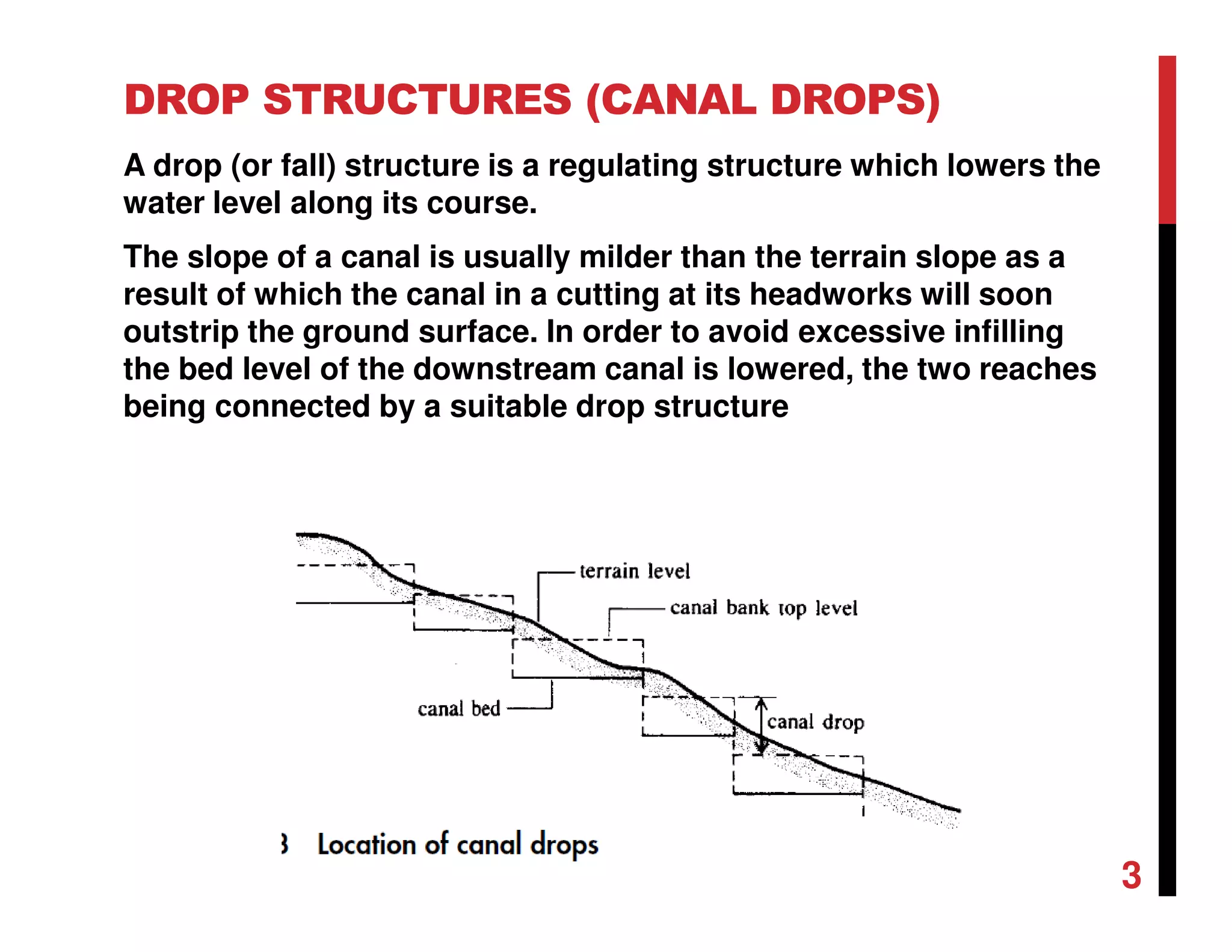
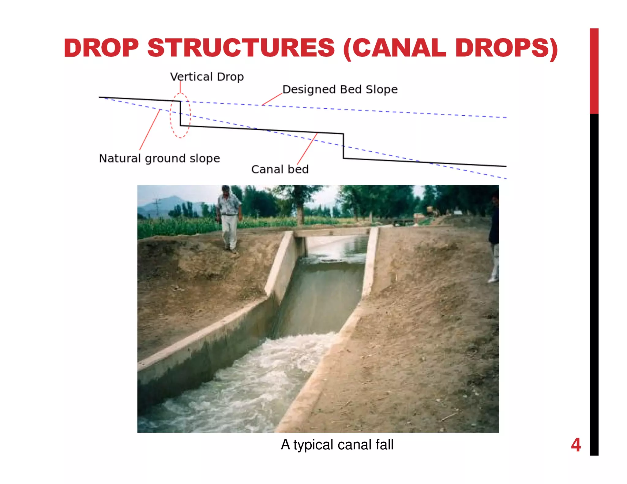
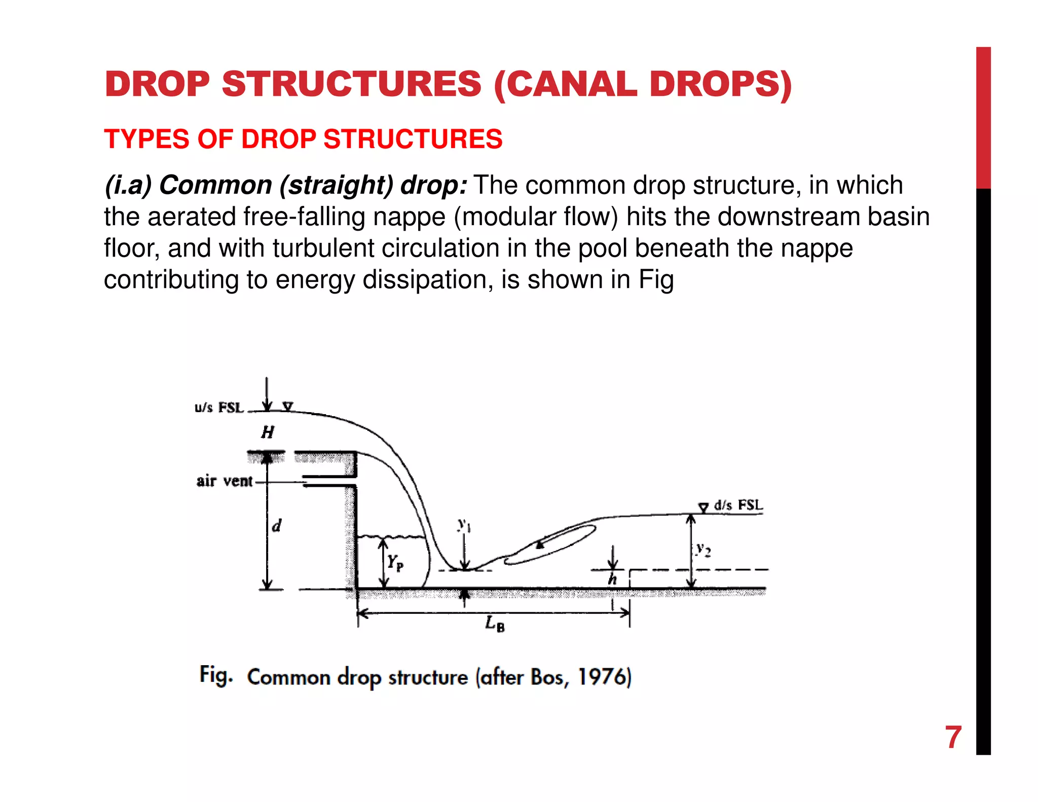
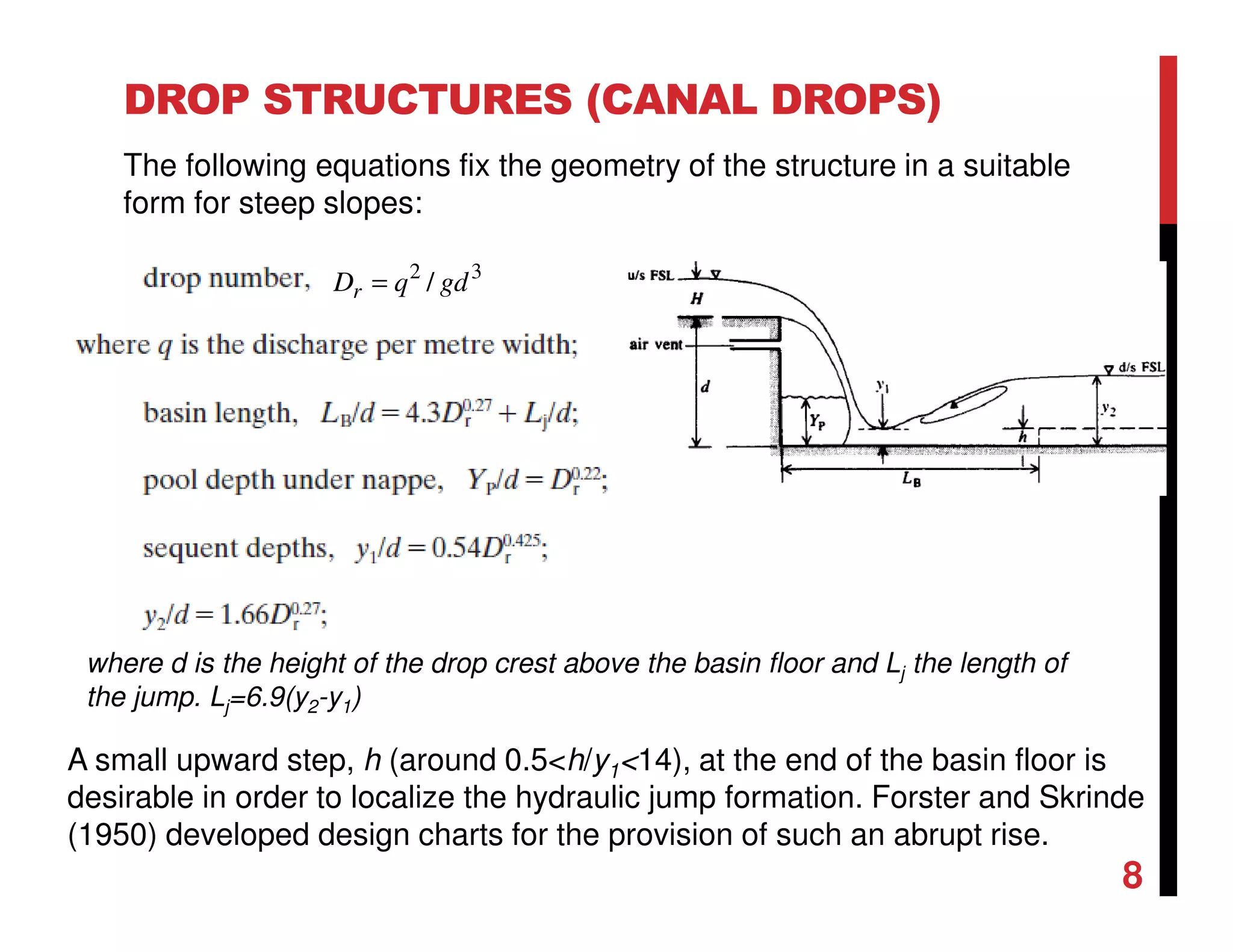
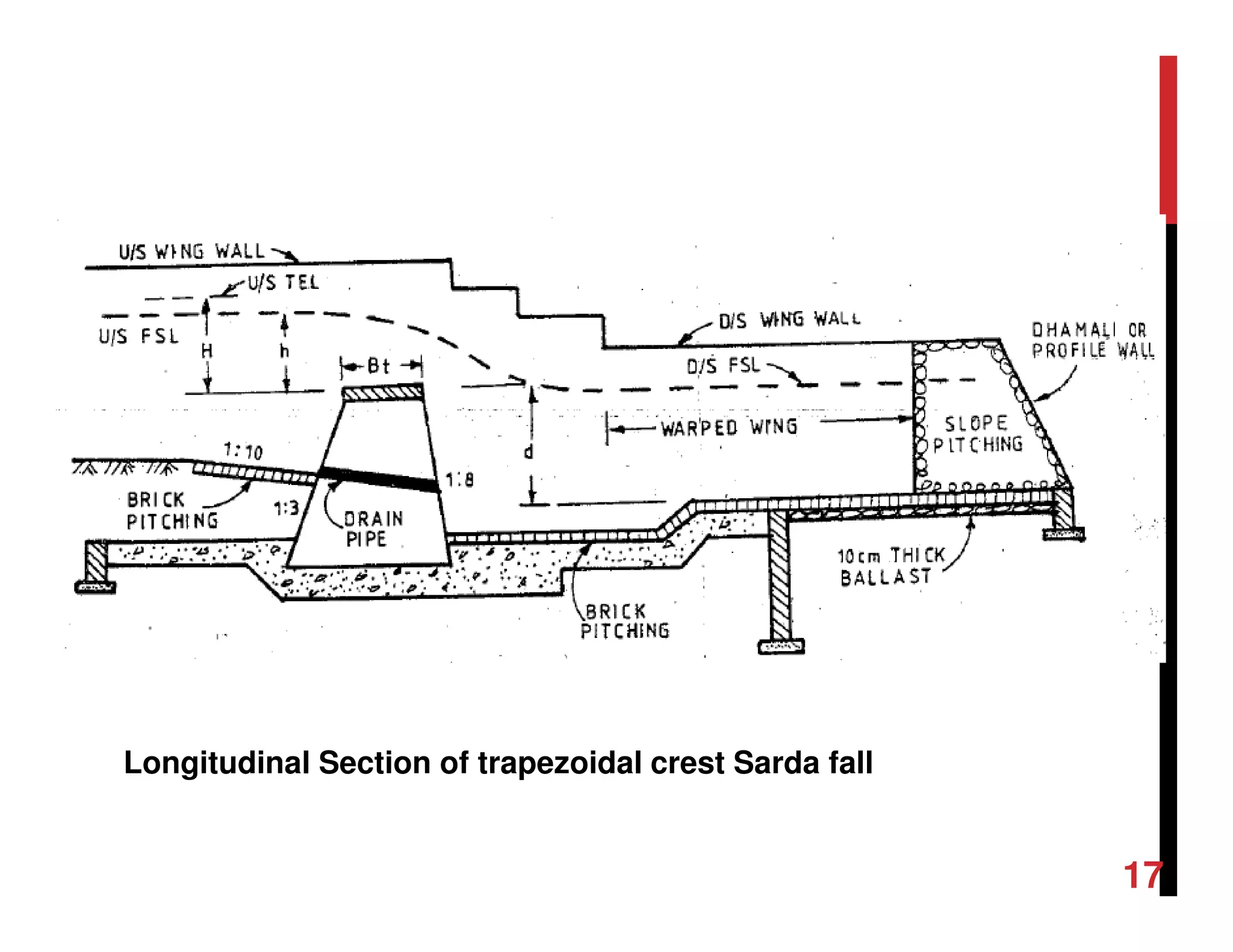
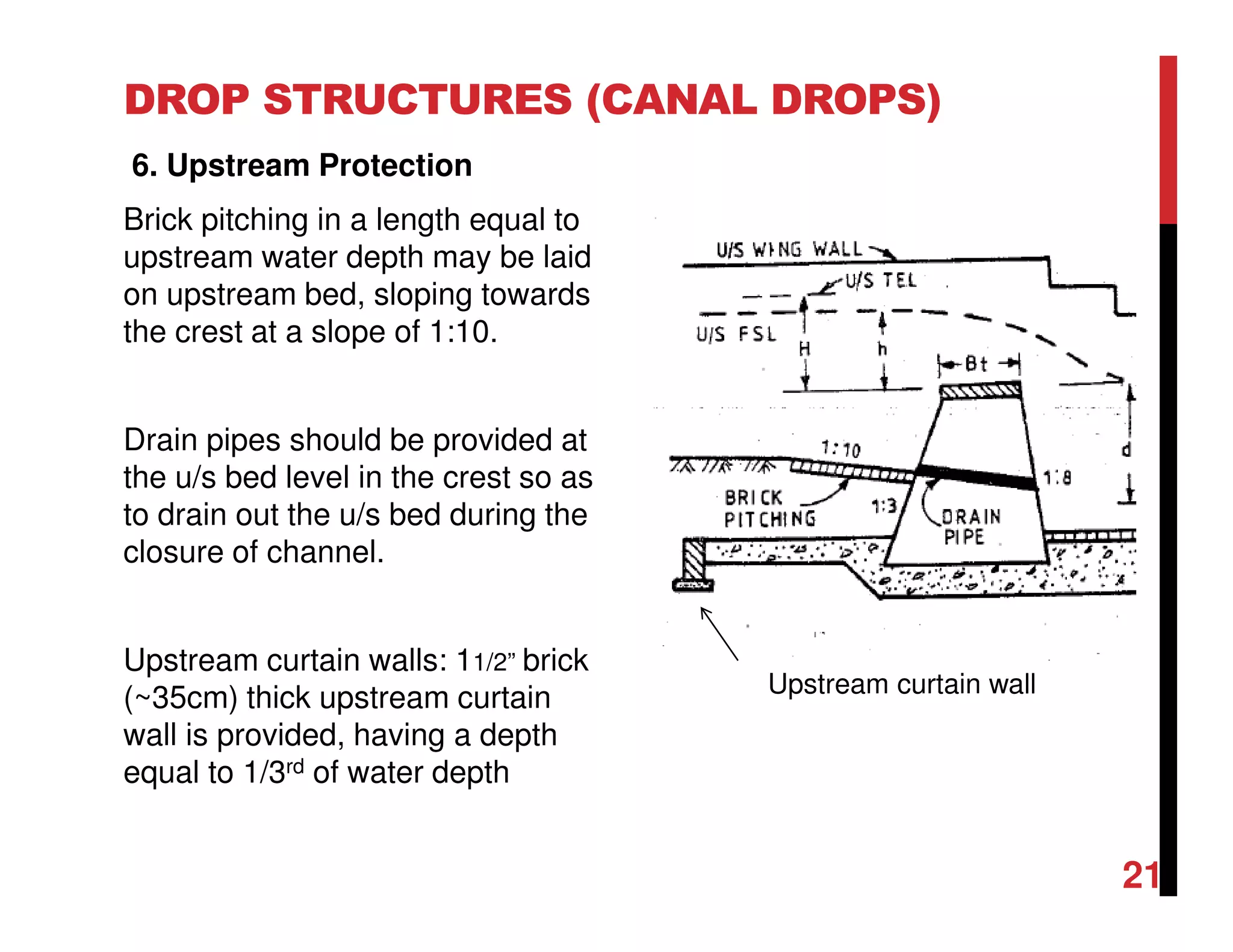

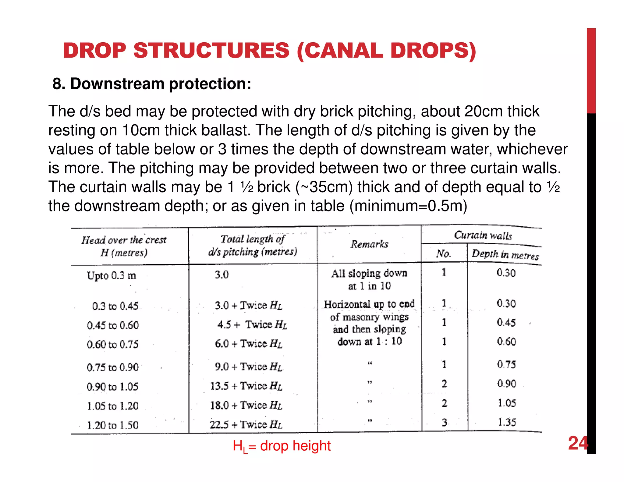
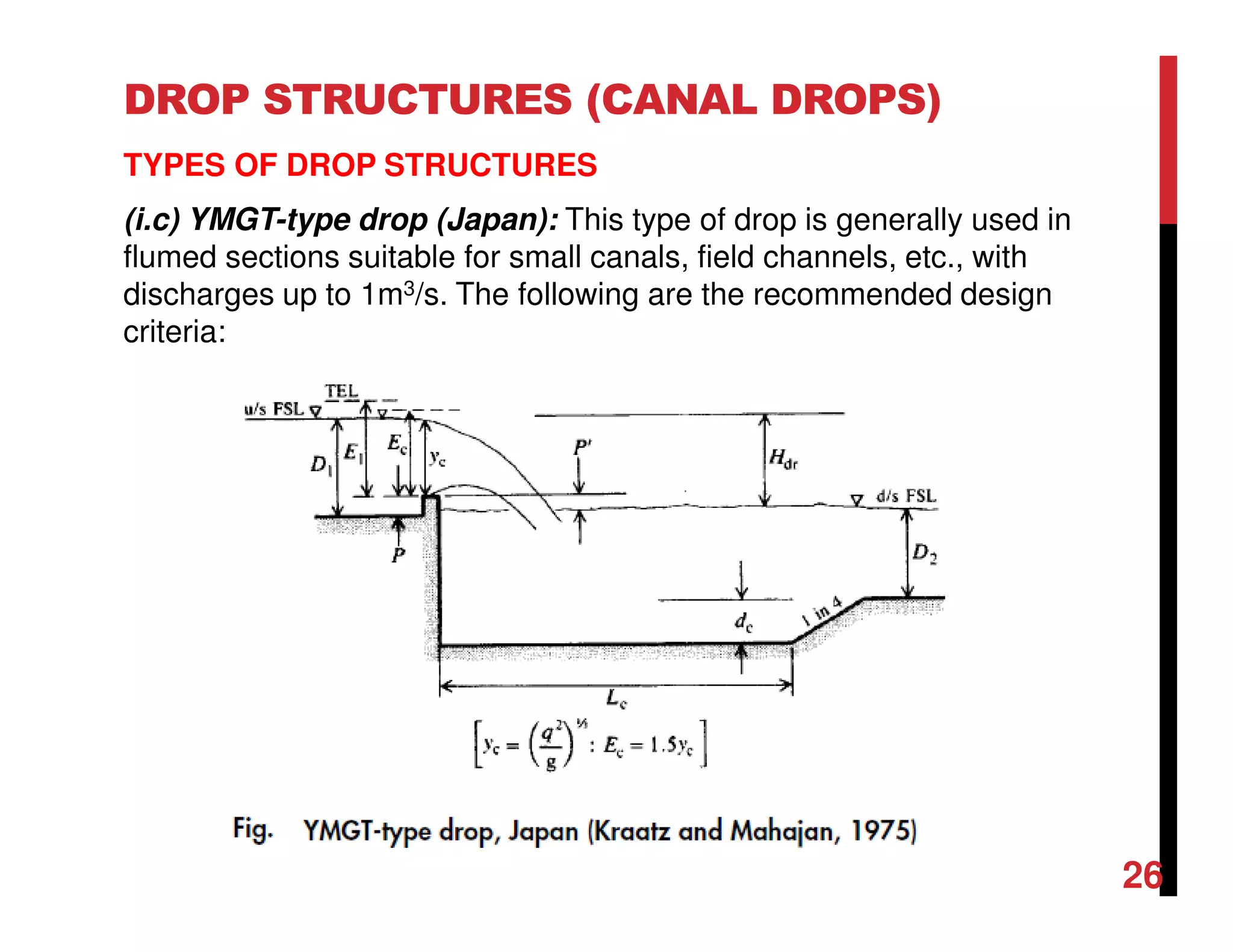
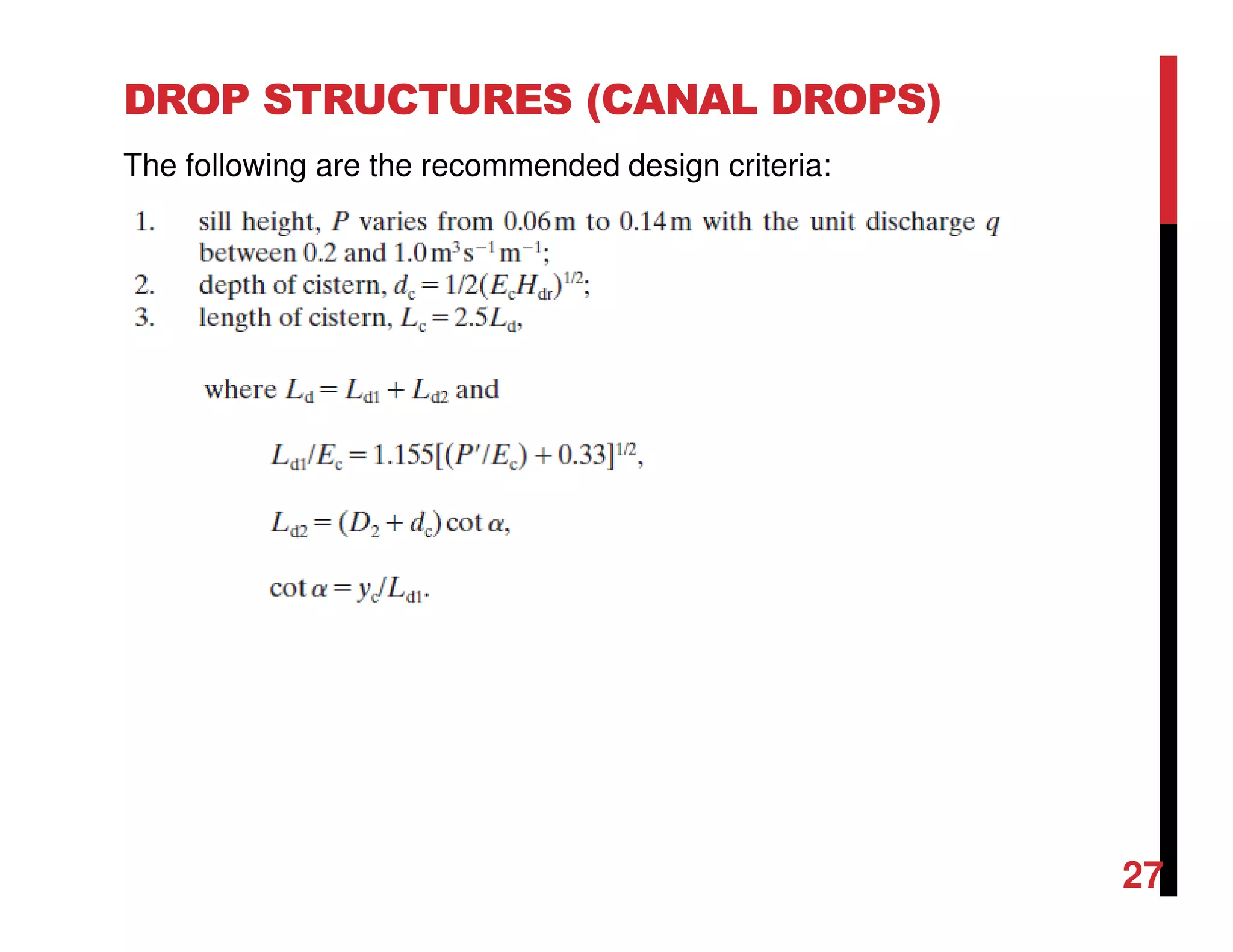
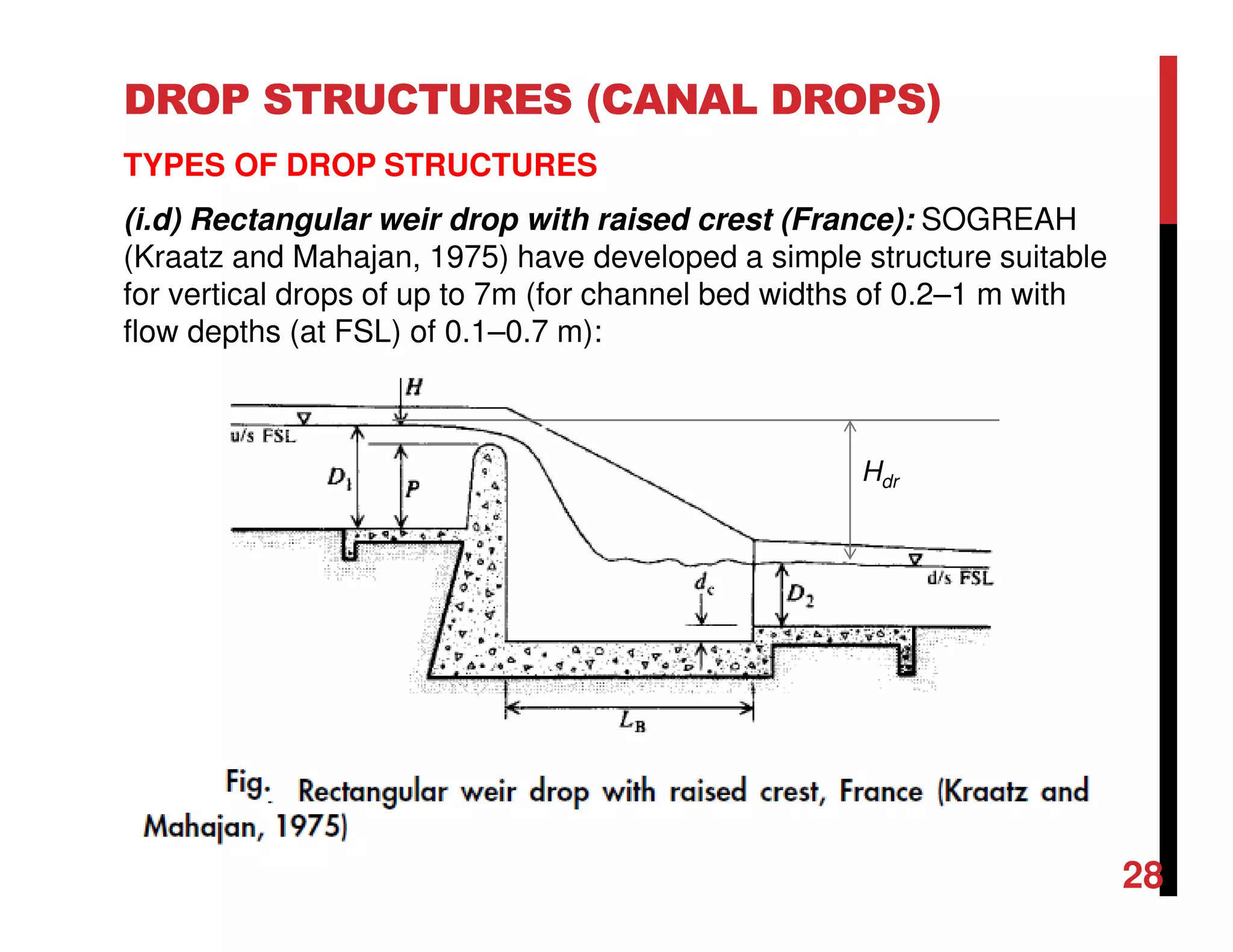
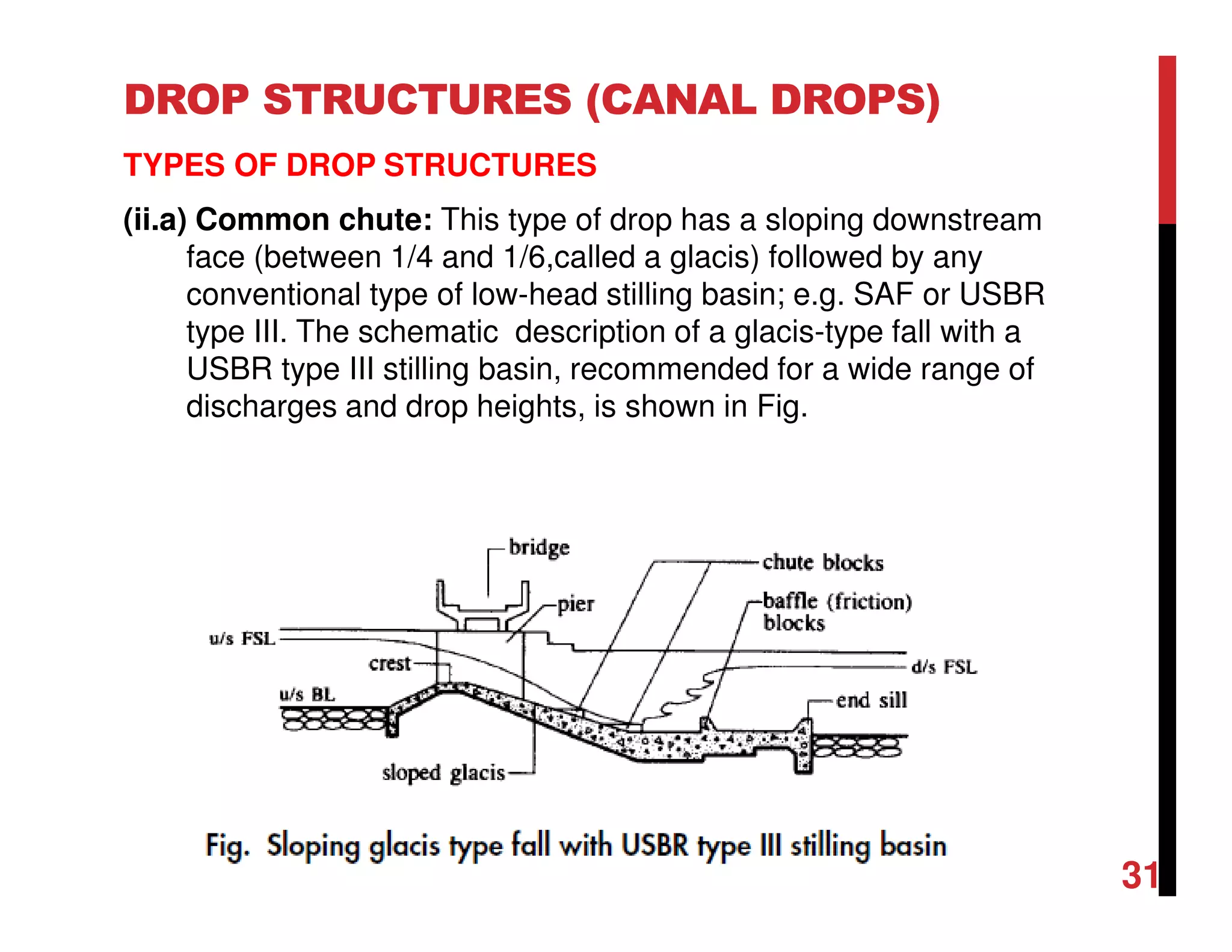
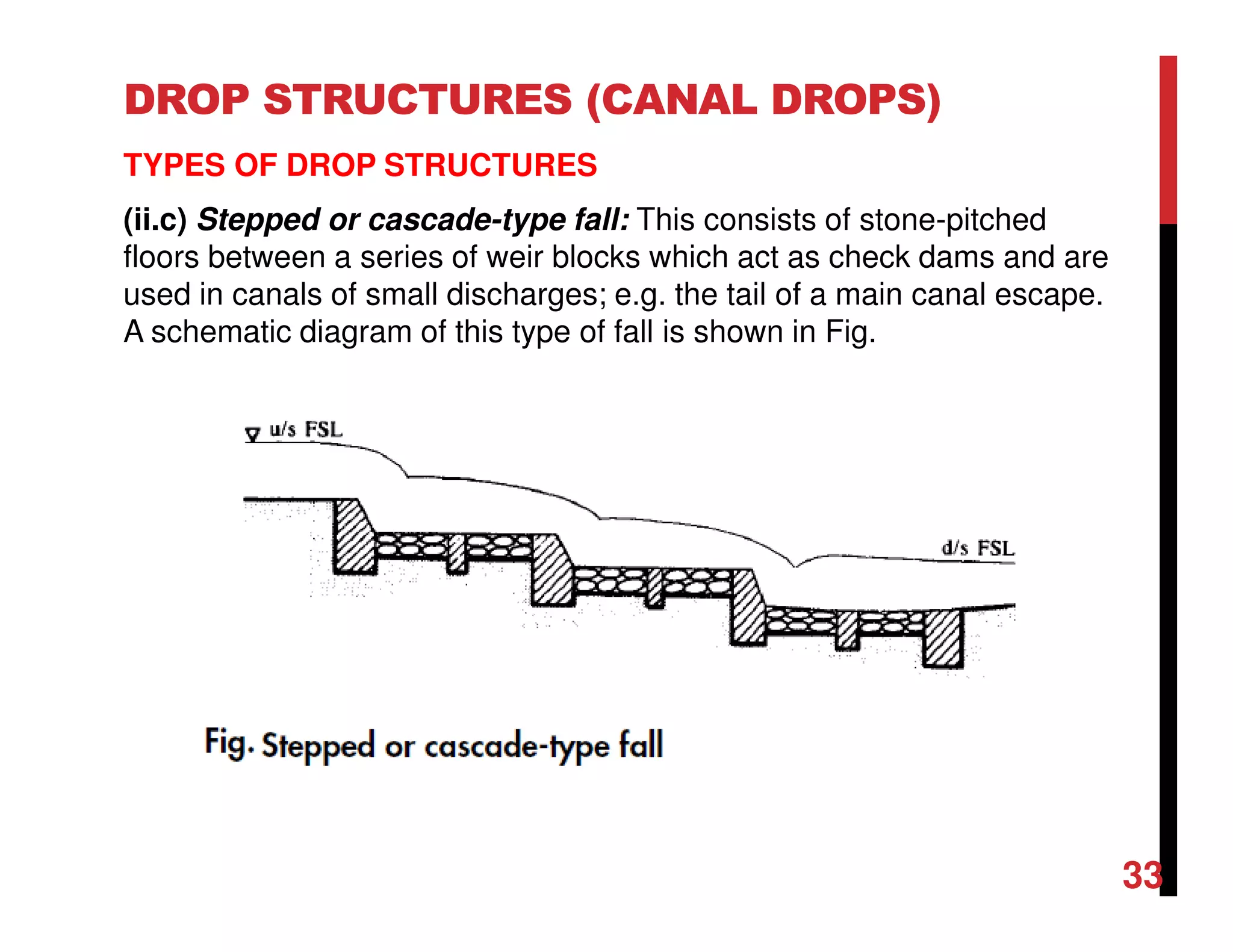
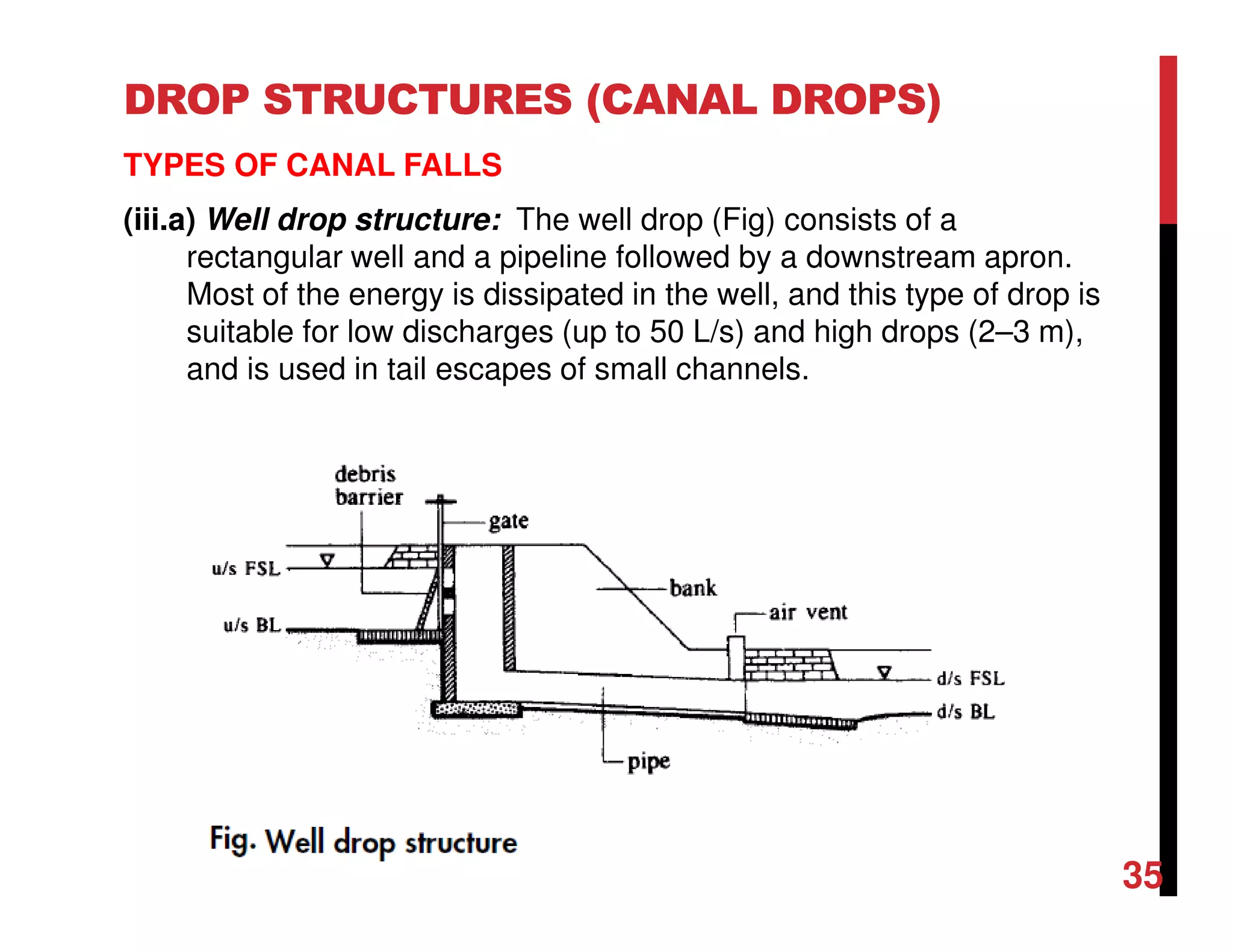

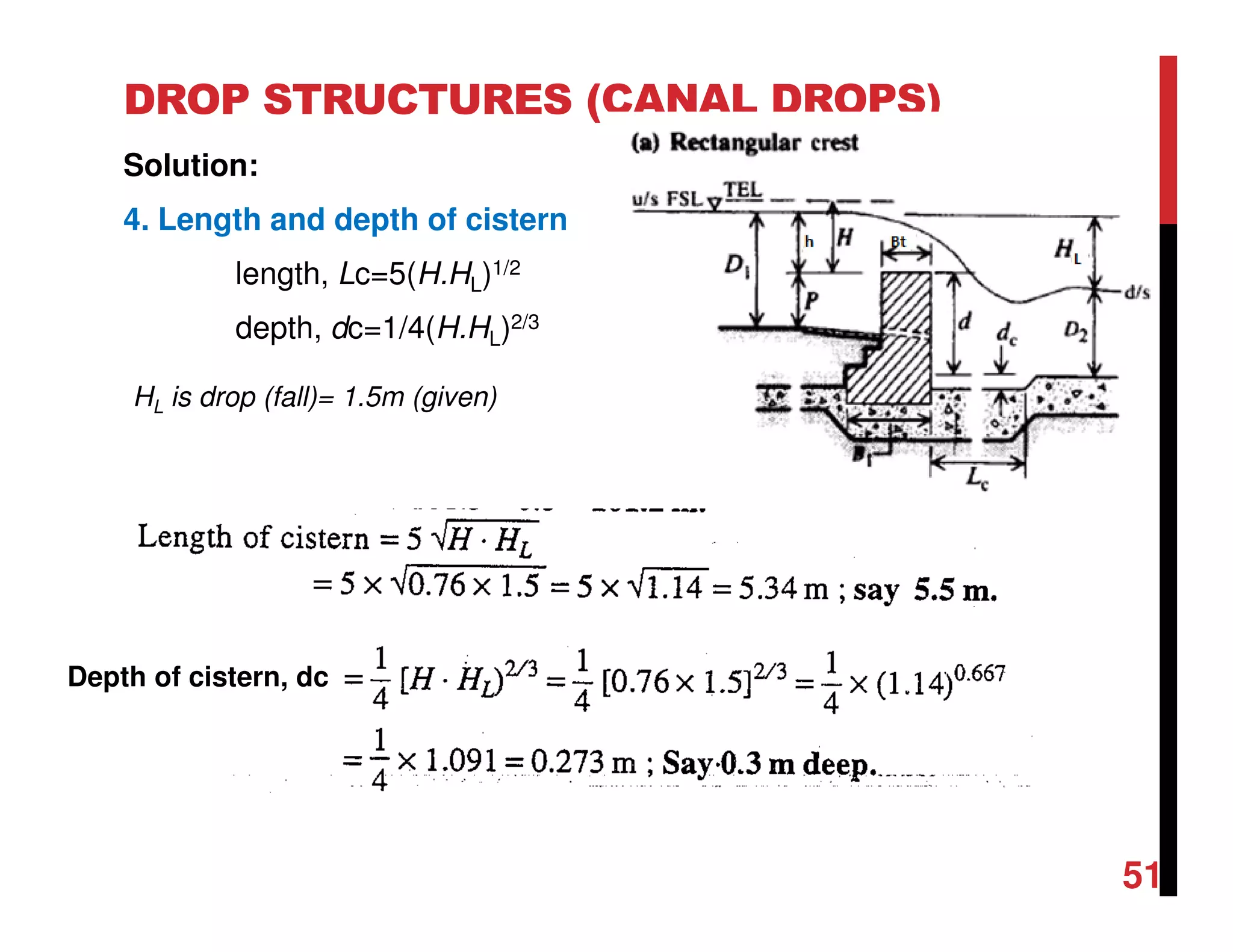


(1) Drop structures are used in canals to lower the water level along its course. There are several types of drop structures including vertical drops, inclined drops, piped drops, and farm drops. (2) The main types of vertical drops discussed are the common straight drop, Sarda-type fall, and YMGT-type drop. Inclined drops include common chutes, rapid fall drops, and stepped cascades. Piped drops can be well drops or pipe falls. (3) Each type has specific design considerations like crest shape and length, basin/stilling pool dimensions, upstream and downstream protections works, and guidelines for selection based on discharge and design head.


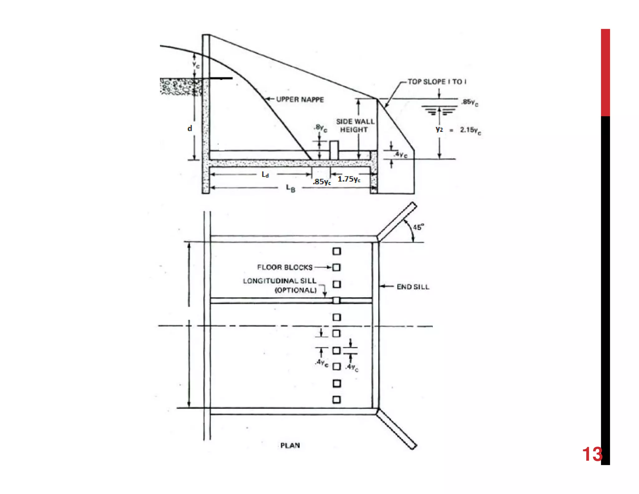
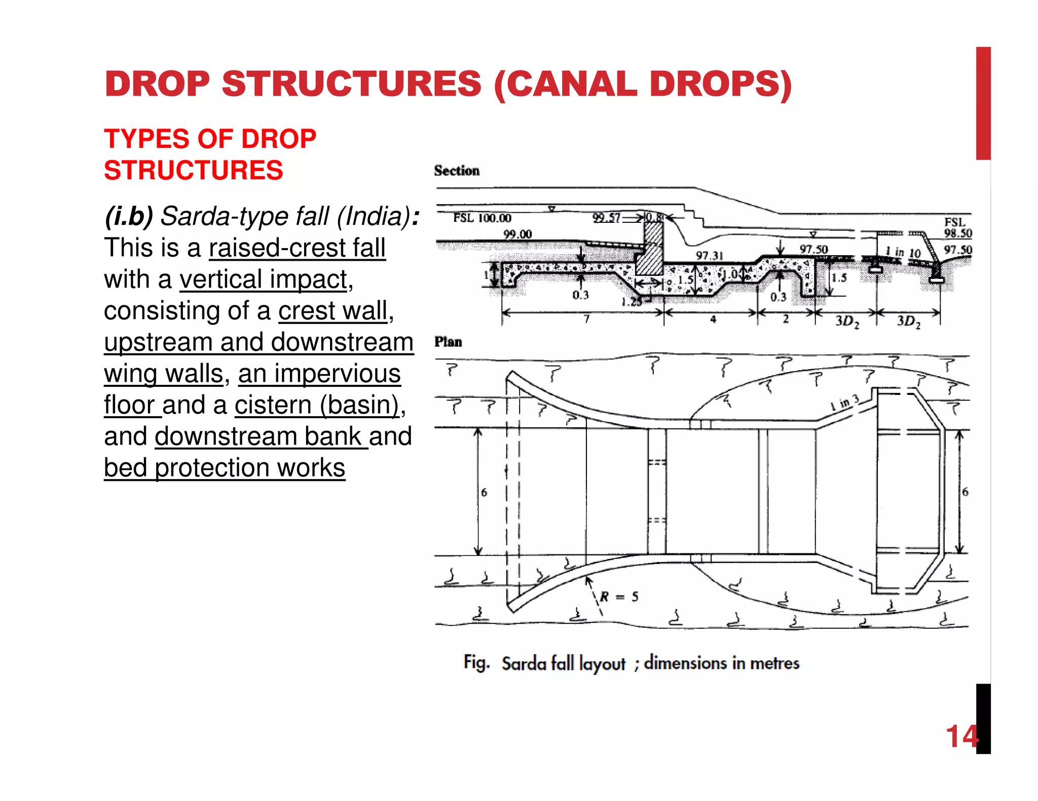
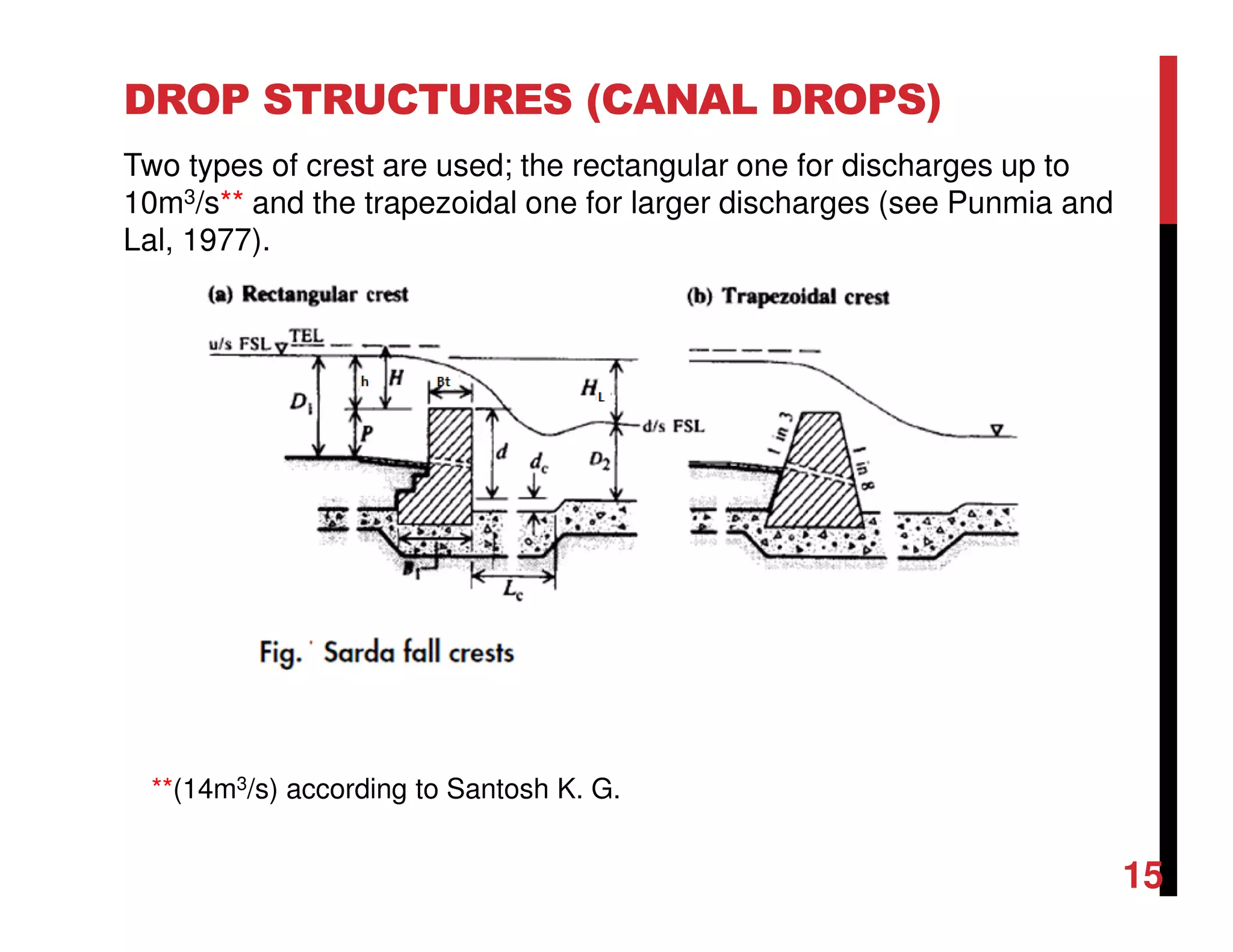
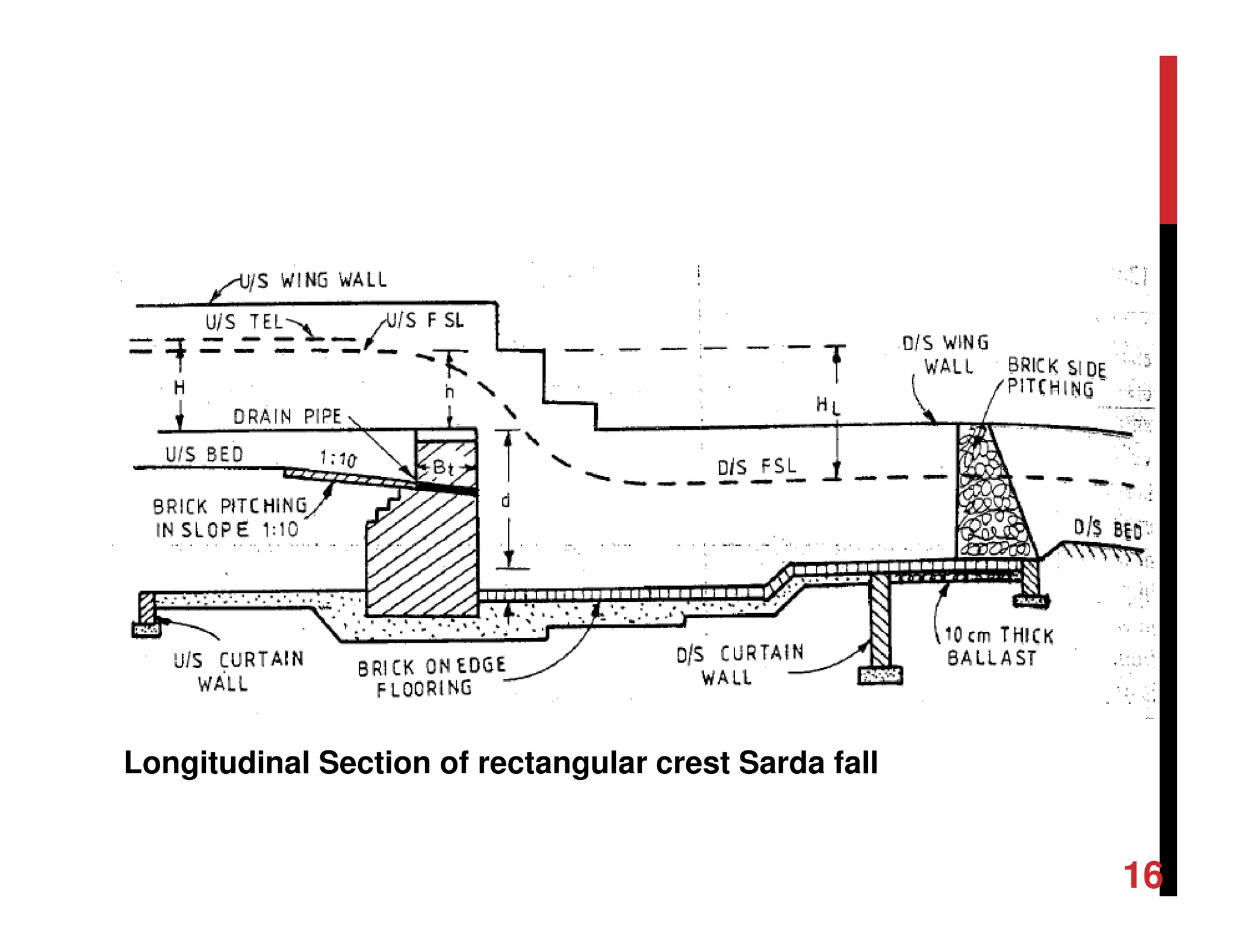
![Engineering Economics: Solved exam problems [ch1-ch4]](https://cdn.slidesharecdn.com/ss_thumbnails/solvedexamproblemsch1-ch4-200220070043-thumbnail.jpg?width=640&height=640&fit=bounds)