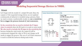
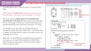
Behavioural Modeling of Sequential Logic
with VHDL
by
Dr. Sunny Atuba
Learning Outcomes
Design a VHDL behavioral model for a sequential logic storage device.
In this presentation, we will look at modeling sequential logic using the more sophisticated
behavioral modeling techniques. We will begin by looking at modeling sequential storage devices.
The goal of this chapter is to provide an understanding of how hardware description languages can
be used to create behavioral models of synchronous digital systems
Modeling Sequential Storage Devices in VHDL
D-latch
Let’s begin with the model of a simple D-Latch. Since the
outputs of this sequential storage device are not updated
continuously, its behavior is modeled using a process. Since
we want to create a synthesizable model, we use a sensitivity
list to trigger the process instead of wait statements.
In the sensitivity list we need to include the C input
since it controls when the D-Latch is in track or store mode.
We also need to include the D input in the sensitivity list
because during the track mode, the output Q will be
continuously assigned the value of D so any change on D
needs to trigger the process. The use of an if/then statement
is used to model the behavior during track mode.
D-Flip-Flop
- The rising edge behavior of a D-Flip-Flop is
modeled using a (Clock’event and Clock= ‘1’)
Boolean condition within a process.
- The (rising_edge(Clock)) function can also be
used for type std_logic.
-The example shows the behavioral model for a
rising edge triggered D-Flip-Flop with both Q
and Qn outputs.
D-Flip-Flop with Asynchronous Reset
- D-Flip-Flops typically have a reset line in order to initialize their
outputs to a known state (e.g., Q =0, Qn = 1).
- Resets are asynchronous, meaning that whenever they are asserted,
assignments to the outputs take place immediately. Asynchronous
resets are more desirable not only to put the D-Flip-Flops into a
known state at start-up but also to recover from a system failure
that may have impacted the clock signal.
- If a reset was synchronous, the output assignments would only take
place on the next rising edge of the clock. This behavior is
undesirable because if there is a system failure, there is no
guarantee that a clock edge will ever occur. Thus, the reset may
never take place.
- In order to model this asynchronous behavior, the reset signal is
placed in the sensitivity list. This allows both the clock and the
reset inputs to trigger the process. Within the process, an
if/then/elsif statement is used to determine whether the reset
has been asserted or a rising edge of the clock has occurred.
- The if/then/elsif statement first checks whether the reset
input has been asserted. If it has, it makes the
appropriate assignments to the outputs (Q = 0, Qn =1).
- If the reset has not been asserted, the elsif clause checks
whether a rising edge of the clock has occurred using
the (Clock’event and Clock = ‘1’) Boolean condition. If
it has, the outputs are updated accordingly (Q <= D, Qn
<= not D).
- A final else statement is not included so that
assignments to the outputs are not made under any
other condition. This models the store behavior of the
D-Flip-Flop.
- The example shows the behavioral model for a rising
edge triggered D-Flip-Flop with an asynchronous, active
LOW reset.
- A D-Flip-Flop with both an asynchronous
reset and asynchronous preset is handled in a
similar manner as the D-Flip-Flop in the prior
section.
- The preset input is included in the sensitivity
list in order to trigger the process whenever a
transition occurs on either the clock, reset, or
preset inputs.
- An if/then/elsif statement is used to first
check whether a reset has occurred; then
whether a preset has occurred; and finally,
whether a rising edge of the clock has
occurred.
- The example shows the model for a rising
edge triggered D-Flip-Flop with asynchronous,
active LOW reset and preset.
D-Flip-Flop with Asynchronous Reset and Preset
- An enable input is also a common feature of modern D-Flip-
Flops.
- Enable inputs are synchronous, meaning that when they are
asserted, action is only taken on the rising edge of the clock.
- This means that the enable input is not included in the
sensitivity list of the process. Since action is only taken when
there is a rising edge of the clock, a nested if/then statement is
included beneath the elsif (Clock’event and Clock =‘1’) clause.
- The example shows the model for a D-Flip-Flop with a
synchronous enable (EN) input. When EN= 1, the D-Flip-Flop
is enabled, and assignments are made to the outputs only on the
rising edge of the clock.
- When EN = 0, the D-Flip-Flop is disabled, and assignments to
the outputs are not made. When disabled, the D-Flip-Flop
effectively ignores rising edges on the clock, and the outputs
remain at their last values.
D-Flip-Flop with Synchronous Enable
• LaMeres, B.J., 2019. Introduction to logic circuits & logic design with VHDL.
Springer.
REFERENCES

Flip-flop , VHDL.pptx

  • 1.
    Behavioural Modeling ofSequential Logic with VHDL by Dr. Sunny Atuba
  • 2.
    Learning Outcomes Design aVHDL behavioral model for a sequential logic storage device.
  • 3.
    In this presentation,we will look at modeling sequential logic using the more sophisticated behavioral modeling techniques. We will begin by looking at modeling sequential storage devices. The goal of this chapter is to provide an understanding of how hardware description languages can be used to create behavioral models of synchronous digital systems Modeling Sequential Storage Devices in VHDL
  • 4.
    Modeling Sequential StorageDevices in VHDL D-latch Let’s begin with the model of a simple D-Latch. Since the outputs of this sequential storage device are not updated continuously, its behavior is modeled using a process. Since we want to create a synthesizable model, we use a sensitivity list to trigger the process instead of wait statements. In the sensitivity list we need to include the C input since it controls when the D-Latch is in track or store mode. We also need to include the D input in the sensitivity list because during the track mode, the output Q will be continuously assigned the value of D so any change on D needs to trigger the process. The use of an if/then statement is used to model the behavior during track mode.
  • 5.
    D-Flip-Flop - The risingedge behavior of a D-Flip-Flop is modeled using a (Clock’event and Clock= ‘1’) Boolean condition within a process. - The (rising_edge(Clock)) function can also be used for type std_logic. -The example shows the behavioral model for a rising edge triggered D-Flip-Flop with both Q and Qn outputs.
  • 6.
    D-Flip-Flop with AsynchronousReset - D-Flip-Flops typically have a reset line in order to initialize their outputs to a known state (e.g., Q =0, Qn = 1). - Resets are asynchronous, meaning that whenever they are asserted, assignments to the outputs take place immediately. Asynchronous resets are more desirable not only to put the D-Flip-Flops into a known state at start-up but also to recover from a system failure that may have impacted the clock signal. - If a reset was synchronous, the output assignments would only take place on the next rising edge of the clock. This behavior is undesirable because if there is a system failure, there is no guarantee that a clock edge will ever occur. Thus, the reset may never take place. - In order to model this asynchronous behavior, the reset signal is placed in the sensitivity list. This allows both the clock and the reset inputs to trigger the process. Within the process, an if/then/elsif statement is used to determine whether the reset has been asserted or a rising edge of the clock has occurred.
  • 7.
    - The if/then/elsifstatement first checks whether the reset input has been asserted. If it has, it makes the appropriate assignments to the outputs (Q = 0, Qn =1). - If the reset has not been asserted, the elsif clause checks whether a rising edge of the clock has occurred using the (Clock’event and Clock = ‘1’) Boolean condition. If it has, the outputs are updated accordingly (Q <= D, Qn <= not D). - A final else statement is not included so that assignments to the outputs are not made under any other condition. This models the store behavior of the D-Flip-Flop. - The example shows the behavioral model for a rising edge triggered D-Flip-Flop with an asynchronous, active LOW reset.
  • 8.
    - A D-Flip-Flopwith both an asynchronous reset and asynchronous preset is handled in a similar manner as the D-Flip-Flop in the prior section. - The preset input is included in the sensitivity list in order to trigger the process whenever a transition occurs on either the clock, reset, or preset inputs. - An if/then/elsif statement is used to first check whether a reset has occurred; then whether a preset has occurred; and finally, whether a rising edge of the clock has occurred. - The example shows the model for a rising edge triggered D-Flip-Flop with asynchronous, active LOW reset and preset. D-Flip-Flop with Asynchronous Reset and Preset
  • 9.
    - An enableinput is also a common feature of modern D-Flip- Flops. - Enable inputs are synchronous, meaning that when they are asserted, action is only taken on the rising edge of the clock. - This means that the enable input is not included in the sensitivity list of the process. Since action is only taken when there is a rising edge of the clock, a nested if/then statement is included beneath the elsif (Clock’event and Clock =‘1’) clause. - The example shows the model for a D-Flip-Flop with a synchronous enable (EN) input. When EN= 1, the D-Flip-Flop is enabled, and assignments are made to the outputs only on the rising edge of the clock. - When EN = 0, the D-Flip-Flop is disabled, and assignments to the outputs are not made. When disabled, the D-Flip-Flop effectively ignores rising edges on the clock, and the outputs remain at their last values. D-Flip-Flop with Synchronous Enable
  • 10.
    • LaMeres, B.J.,2019. Introduction to logic circuits & logic design with VHDL. Springer. REFERENCES

Editor's Notes

  • #5 The rising_edge function function rising_edge ( signal s : std_ulogic ) return boolean; Detects the rising edge of a std_ulogic or std_logic signal. It will return true when the signal changes from a low value ('0' or 'L') to a high value ('1' or 'H’). Examples In this example, the simulator executes the body of the if exactly once per clock cycle, on the rising edge of the clock signal. signal clock : std_logic; ... sync_stuff: process (clock) begin if rising_edge(clock) then ... end if; end process; Return to The std_logic_1164 library.
  • #8 An active low reset means the circuit is reset when the input is driven low, that is, Active Low “reset” input goes low (more negative) to reset the circuit. Active High “reset” input goes high (more positive) to reset the circuit.