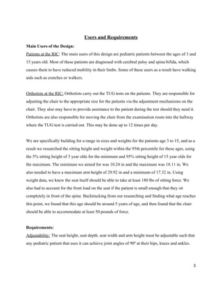
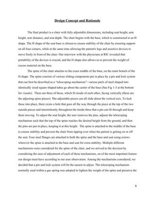
This document provides a summary of a team's design of an adjustable pediatric chair for mobility assessments. The chair was designed for patients aged 3-15 at a rehabilitation institute. The chair needs to be adjustable to accommodate patients of varying sizes and allow them to sit at 90 degree angles. The design consists of an H-shaped base with a telescoping spine that can be adjusted in height using a pin-locking system. The seat, backrest, and armrests are also adjustable to accommodate different patients. The team's design aims to meet requirements for adjustability, portability, safety, durability and build quality.


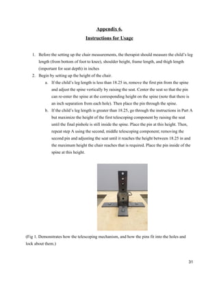
![Appendix 7.
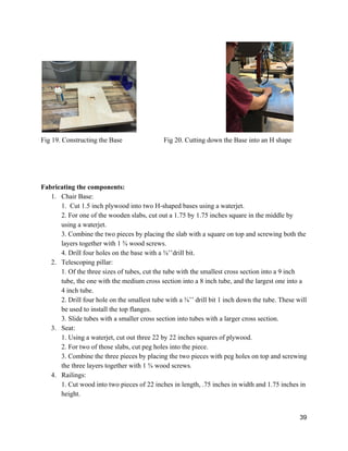
Instructions for Construction
Instructions for constructing the prototype:
Materials:
Table 1: Materials used for Construction:
Materials Specifications Quantity
Heavy Duty Steel
BoltTogether Framing
2” Square Tube, 4’ Long 1
Heavy Duty Steel
BoltTogether Framing
1.75” Square Tube, 4’ Long 1
Heavy Duty Steel
BoltTogether Framing
1.5” Square Tube, 4‘ Long 1
Plywood Sheathing ½” (15/32) x 4’x 8’ 2
Pony Adjustable Clamps 5"
Carriage CClamp
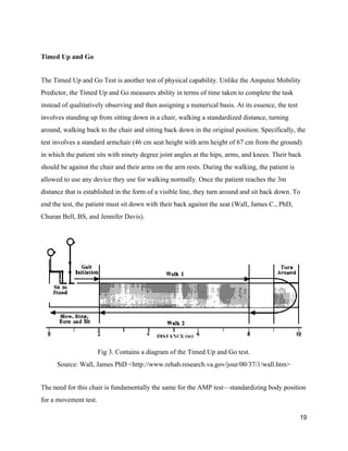
5” Opening, 3.25” Reach 2
Bolts [Inches] Long, “ Diameter 4
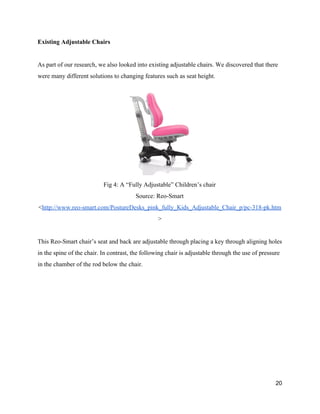
screws carbon steel wood screws 30
Pins with wraparound lock .37” diameter, 6” long 4
Note: See Bill of Materials for more detail on cost and specifications.
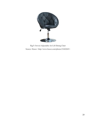
The following tools/equipment are required for constructing the chair:
Band Saw
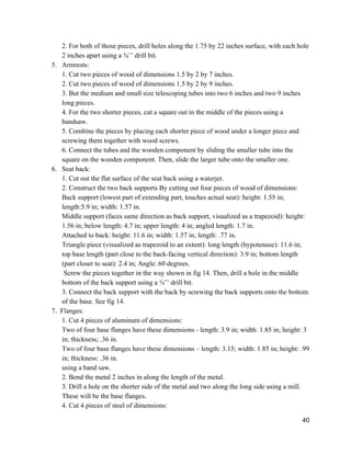
33](https://image.slidesharecdn.com/ca3c834d-5eb0-4e0a-b49e-275d031d1def-160509060143/85/FinalReport-34-320.jpg)
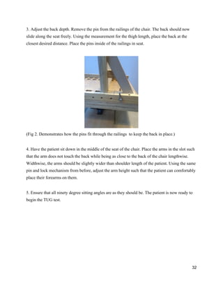
![Water Jet
Power Sander and Sandpaper
Mallet
Screwdriver
Handdrill
Dremel tool
Level
Mill
Welding station
Metal bender
[Reference: Length is parallel to direction user faces, width is perpendicular, height is vertical
direction]
Dimensions:
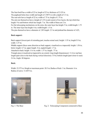
Base:
Width: 24 in; Length 22 in; Thickness; 1.5 in. Width of H extensions (parts that stick out from
main part of the base): 4 in; Length, 6 in.
Depth of Hole: .75 in; center of hole is 12 inches from width of the base, 11 in from the
maximum (including H extensions) length of the base.
Telescoping mechanism fits inside: middle layer: height: 8 in; width and length: 1.75 in;
Outermost tube: height: 4 in; width and length: 2 in;
Innermost tube: height 9 in; width and length: 1.5 in.
The holes in the telescoping mechanisms have diameter: .43 in and are .57 in away from each
other.
Flanges attach to the outer layer.
Two flanges have these dimensions length: 3.9 in; width: 1.85 in; height: 3 in; thickness; .36 in.
Two flanges have these dimensions – length: 3.15; width: 1.85 in; height: .99 in; thickness: .36
in.
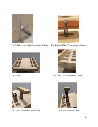
Seat:
Below the seat, the inner telescoping mechanism is attached, with dimensions – height: 8 in;
width and length: 1.5 in.
The flanges attaching the inner mechanism to the seat have dimensions height: .7 in; length: 6
in; width: 1.3 in; thickness: .25 in
34](https://image.slidesharecdn.com/ca3c834d-5eb0-4e0a-b49e-275d031d1def-160509060143/85/FinalReport-35-320.jpg)