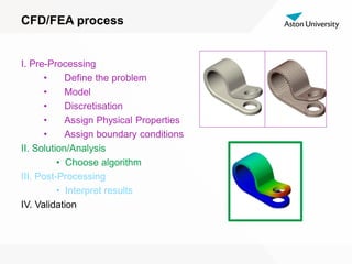
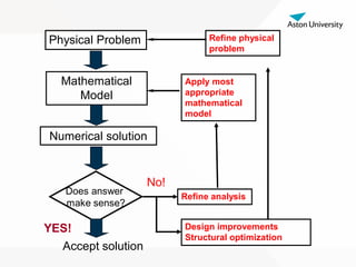
The document summarizes the FEA/CFD process which includes:
1) Defining the problem, creating a model, assigning properties and boundary conditions in pre-processing.
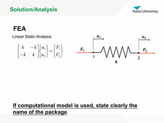
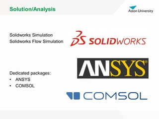
2) Choosing an algorithm and running the analysis/solution in solution/analysis.
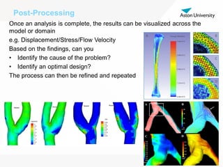
3) Interpreting and visualizing results in post-processing to identify causes and optimal designs.
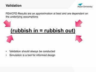
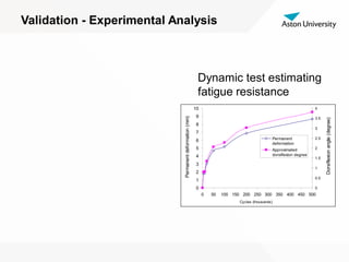
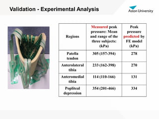
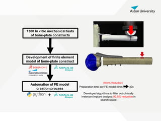
4) Validating simulation results experimentally through methods like 3D printing, dynamic testing, and pressure measurements to verify the model is accurate.


![[English Version]Maker-Ray Product Brochure V3 .pdf](https://cdn.slidesharecdn.com/ss_thumbnails/englishversionmaker-rayproductbrochurev3-260113094444-0156dbdc-thumbnail.jpg?width=640&height=640&fit=bounds)

![Alan Lucas - [Template] [Template] [Template] ScienceFairProjectTemplate.pptx](https://cdn.slidesharecdn.com/ss_thumbnails/alanlucas-templatetemplatetemplatesciencefairprojecttemplate-260106222421-b6ad9ab7-thumbnail.jpg?width=640&height=640&fit=bounds)


