Download as PDF, PPTX
![0 1 2 3 4 5 6 7 8 9
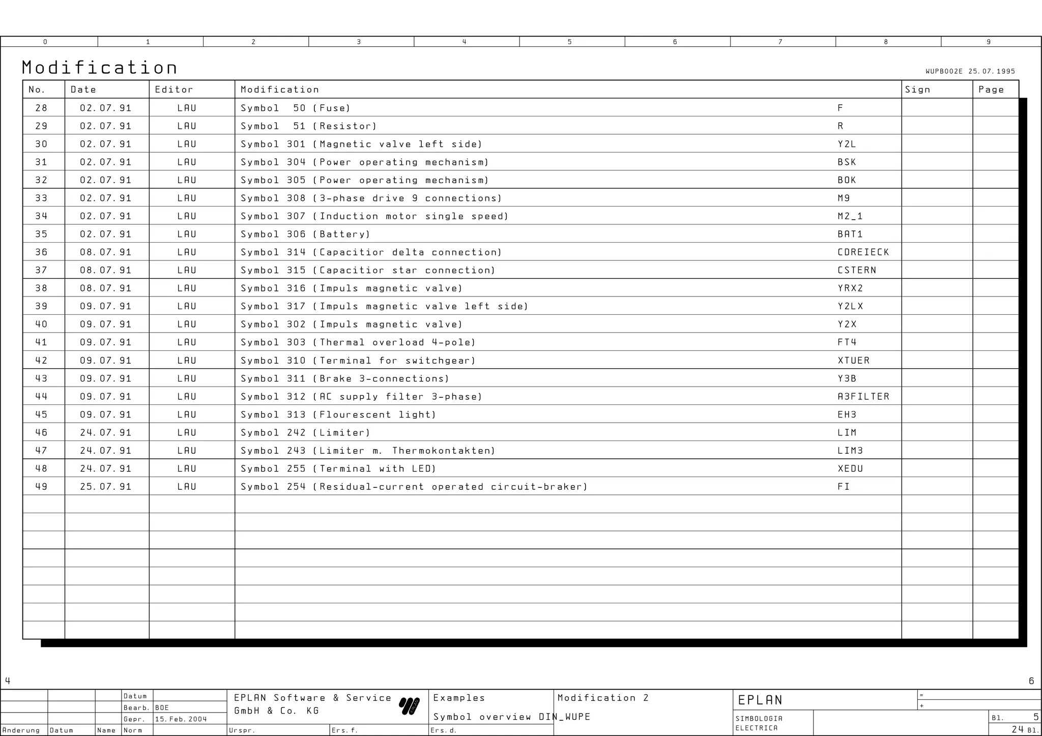
Modification WUPB002E 25.07.1995
No. Date Editor Modification Sign Page
1 18.06.91 LAU Graphical symbol converted to V 4.0
2 18.06.91 LAU Item designation = BMK
3 18.06.91 LAU Press ALT ESC to suppress automatic connecting
4 27.06.91 LAU Various symbol generated as angle variants
5 27.06.91 LAU Various symbol macros generated
6 27.06.91 LAU The following symbols should not longer used (as they exist as angle variants)
#54 [C2] (Kondensator) #101 [HLEDKO] (Leuchtdiode) #52 [R2] (Potentiometer)
#172 [SCHLO] (Schleifring.) #99 [THY2] (Thyristor) #70 [VKU] (Diode Kathode unten)
#162 [XKO2] (Koaxialstecker) #32 [XSB] (Stecker mit Buchse) #205 [XSBO] (Stecker mit Buchse)
7 22.07.91 LAU Symbol name changed:SCHLU -> SCHL; Symbol name changed:HLED -> LED; Symbol name changed:THY1 -> THY
8 22.06.91 LAU Symbol 226 (Battery) BAT
9 25.06.91 LAU Symbol 53 (Capactior) C
10 25.06.91 LAU Symbol 171 (Slipring transformer) SCHL
11 25.06.91 LAU Symbol 55 (Diode) V
12 27.06.91 LAU Symbol 94 (Z-Diode) VZ
13 27.06.91 LAU Symbol 89 (Thyristor) THY
14 27.06.91 LAU Symbol 49 (LED) LED
15 28.06.91 LAU Symbol 153 (Potentiometer) RT
16 28.06.91 LAU Symbol 48 (Magnetic-brake) YB
17 28.06.91 LAU Symbol 104 (Valve coil) (BMK left or right) Y1
18 28.06.91 LAU Symbol 316 (Impulse magnetic valve) (BMK left or right) YRX2
19 28.06.91 LAU Symbol 184 (Ground connector) PE
20 02.07.91 LAU Symbol 161 (Coaxial connector) XKO1
21 02.07.91 LAU Symbol 31 (Socket with plug) XBS
22 02.07.91 LAU Symbol 204 (Socket with plug) XBSD
23 02.07.91 LAU Symbol 306 (Battery) BAT1
24 02.07.91 LAU Symbol 300 (Ground) ERDE
25 02.07.91 LAU Symbol 4 (NC on-delay) OOV
26 02.07.91 LAU Symbol 6 (NC off-delay) OSV
27 02.07.91 LAU Symbol 15 (Changeover contact) W
3 5
Datum =
EPLAN Software & Service Examples Modification 1 EPLAN
Bearb. BOE +
GmbH & Co. KG
Gepr. 15.Feb.2004 Symbol overview DIN_WUPE SIMBOLOGIA Bl. 4
nderung Datum Name Norm Urspr. Ers.f. Ers.d. ELECTRICA 24 Bl.](https://image.slidesharecdn.com/eplan-simbologia-simboloselctricos-120613155639-phpapp01/75/Eplan-simbologia-simbolos-electricos-4-2048.jpg)


![0 1 2 3 4 5 6 7 8 9
Position switches Graphical symbol macros Symbol macros
To make a symbol macro : 1. Put the cursor on the insertion
201/D:STS 202/D:S1 203/D:S2
A point of a symbol. 2. Push the key [B]. 3. Select a screen
Retained switch for Multiposition Multiposition
S? several switching points switch 1 N.C. switch 1 N.O.
6ST6 segment. 4. Insert Name and comment of the macro.
B
255/0 255/0 255/0
Symbol macros called up with [Alt Gr]+[Ins].
Example position switches Example Example symbol macros
1 3 5
3ST1 4ST4 6ST1 QLSO 13 11 _SL
S S S Ground Q? 14 12
4-6,3A
2 4 6
3ST2 5ST1 6ST2 FAHS STS6ST1
87 13 B
S S S Ground1 F? S?
4-6,3A 88 14 1 2 3 4 5 6
3ST3 5ST2 6ST3 WENDE
S S S Brake 1 3 5
F?
?A 2 4 6
4ST1 5ST3 6ST4
S S S Valve
1 3 5 1 3 5
4ST2 5ST4 6ST5 K? K?
2 4 6 2 4 6
S S S DQR
4ST3 5ST5 6ST6
S S S DQL
Position switches are symbols put together from several graphical symbol macro. With [Ctrl]+[F1] = call up graphic Symbol macros contain all components designation
The corresponding graphical symbol macro is entered two step to the right editor. (Item designation etc.) which belong to the symbol.
of the attachment point of the operating element graphical symbol. With [Ctrl]+[F5] = create macro. Example: QLSO, _SL, FAHS and STS6ST1.
With [M] = insert macro,
The switch positions (S1 for close, S2 for open) are to be inserted in steps Symbol macros can contain more than one symbol.
example: GROUND.MFE
of one beginning for steps to the right. Example: WENDE
22 24
Datum =
EPLAN Software & Service Examples Position switches EPLAN
Bearb. BOE +
GmbH & Co. KG Graphical symbol macros
Gepr. 15.Feb.2004 Symbol overview DIN_WUPE SIMBOLOGIA Bl. 23
Symbol macros ELECTRICA
nderung Datum Name Norm Urspr. Ers.f. Ers.d. 24 Bl.](https://image.slidesharecdn.com/eplan-simbologia-simboloselctricos-120613155639-phpapp01/75/Eplan-simbologia-simbolos-electricos-23-2048.jpg)
![0 1 2 3 4 5 6 7 8 9
EPLAN - Basicsymbols Not used symbols
1P0B2H
16/D:OWU 101/D:HLEDKO
Basic symbols only exist of standard connecting points.
Changeover LED
They be of use as simplification to work out some new symbols. contact 255/0
002/0
Basic symbols are saved in the directory EPLAN4N with the
extension *.GSB . Please use symbol: Please use symbol:
They are build like the following example : O HLED
Angle variant 2/180ø Angle variant 2/180ø
2P2B4H Example: 2P2B4H
18/D:SWU 162/D:XKO2
Changeover Coaxial
<number of pathes> P <height> H contact connector
002/0 255/0
<width> B
Please use symbol: Please use symbol:
W XKO1
Angle variant 2/180ø Angle variant 2/180ø
2P4B4H The notifications "height" and "width" are in a 4mm distance.
32/D:XSB 172/D:SCHLO
Plug with Slipring
Selecting "2P2B4H" will insert a basic symbol with two upper socket transformer
and two lower connecting point. 100/0 255/0
The horizontal pathes are 8mm appart. The vertical pathes are
16mm appart. Please use symbol: Please use symbol:
XBS SCHL
Angle variant 2/180ø Angle variant 2/180ø
3P2B2H
54/D:C2 183/D:EH2
Capacitor Flourescent
Building up a new symbol with basic symbols. for rectifier light
---------------------------------------------------------- 255/0 255/0
1. Use the key [INS].
2. Read in a symbol.
3. Call up the symbol editor [ALT]+[S]. Please use symbol: Please use symbol:
4. Call up with [ALT]+[F10]: import C EH4
export Angle variant 1/90ø Angle variant 1/90ø
basic symbols
5. Chose the selection basic symbol.
3P2B4H A window with the basic symbol files will be open.
70/D:VKU 205/D:XSBD
6. Chose a basic symbol,for example: 2P2B4H.
Diode Plug with socket
7. Draw up a new symbol graphic. 255/0 without x-ref
Make a new insert for the components designations. 255/0
Please use symbol: Please use symbol:
V XBSD
Angle variant 2/180ø Angle variant 2/180ø
23
Datum =
EPLAN Software & Service Examples EPLAN-Basicsymbols EPLAN
Bearb. BOE +
GmbH & Co. KG Not used symbols
Gepr. 15.Feb.2004 Symbol overview DIN_WUPE SIMBOLOGIA Bl. 24
nderung Datum Name Norm Urspr. Ers.f. Ers.d. ELECTRICA 24 Bl.](https://image.slidesharecdn.com/eplan-simbologia-simboloselctricos-120613155639-phpapp01/75/Eplan-simbologia-simbolos-electricos-24-2048.jpg)

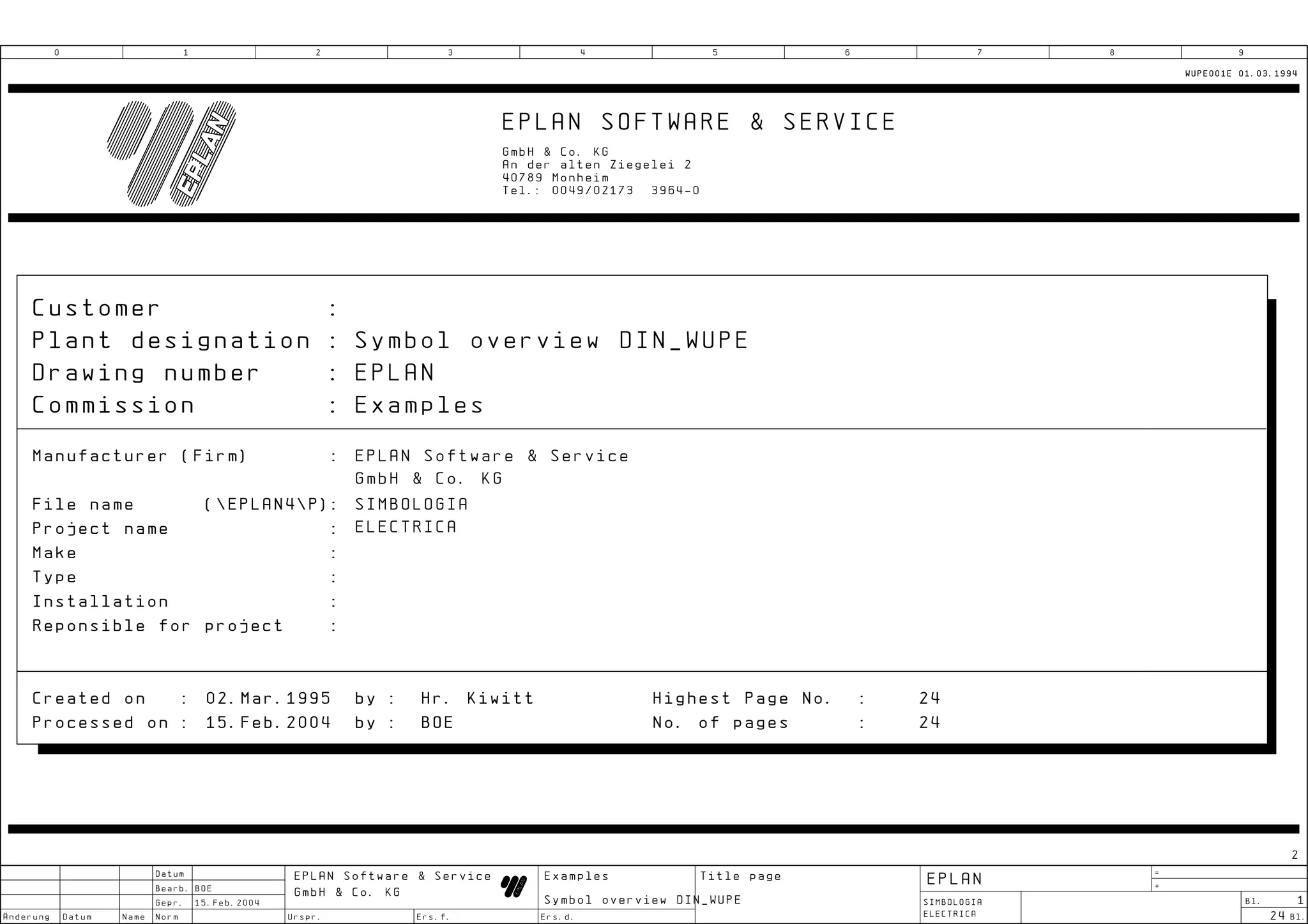
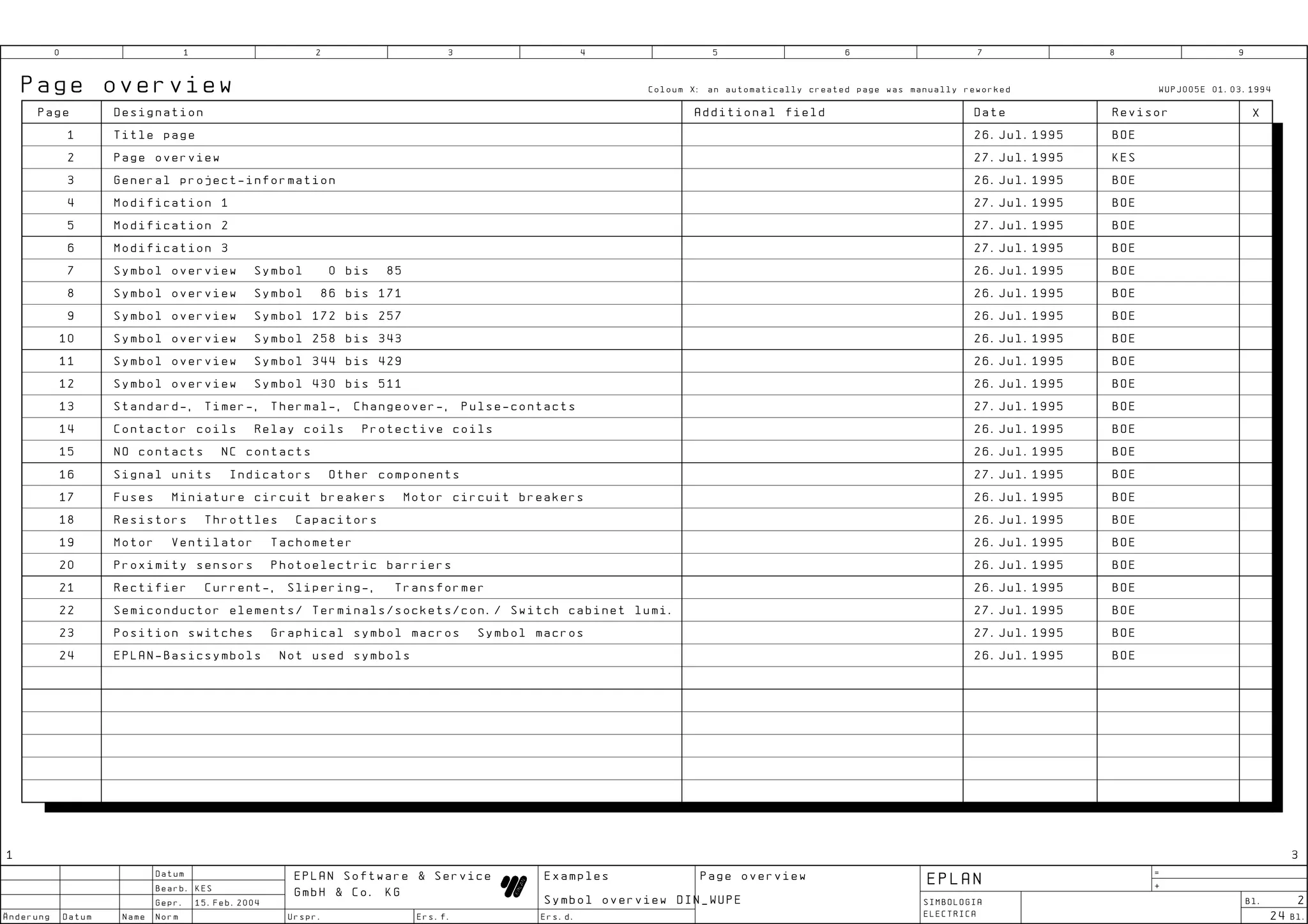
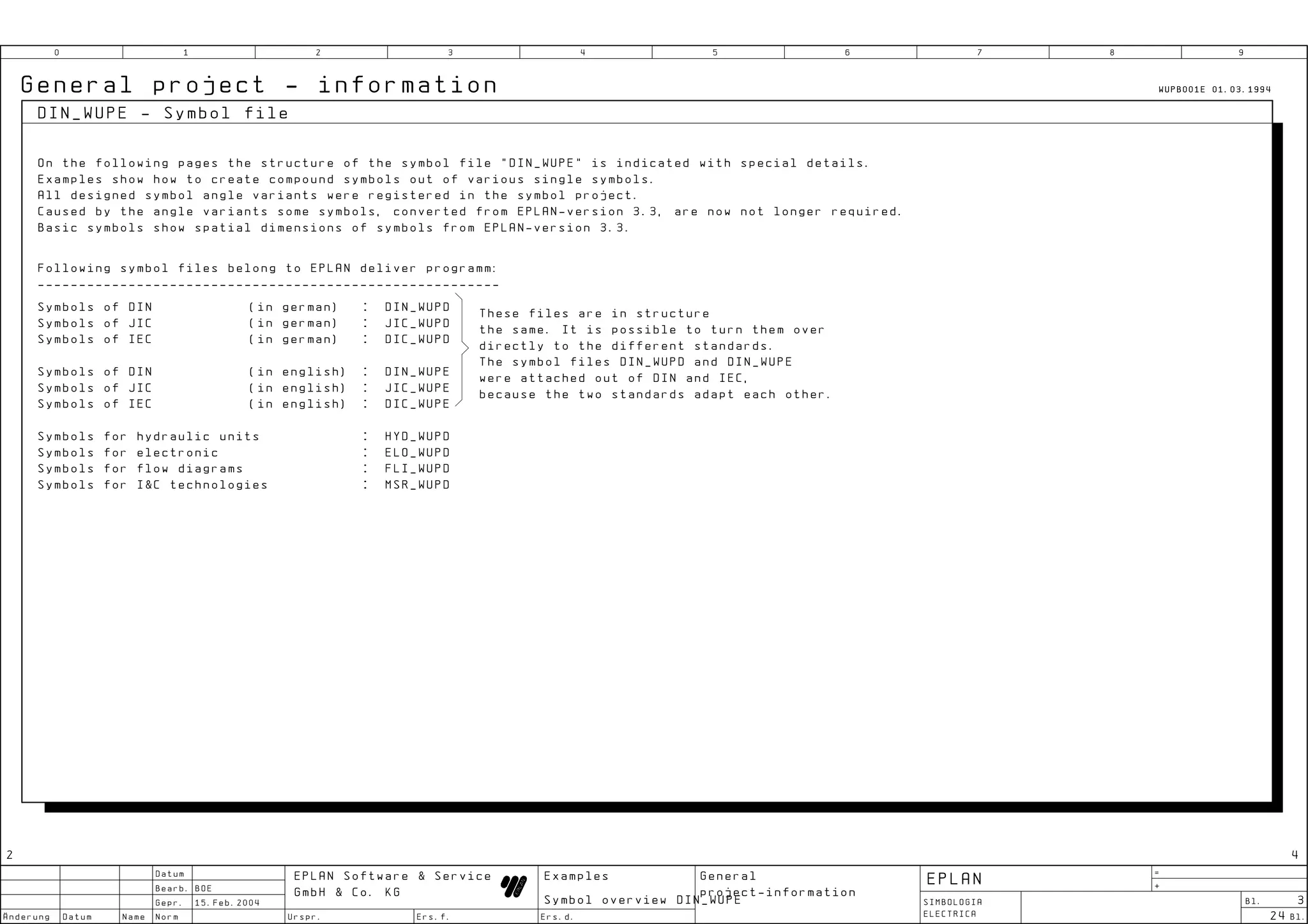
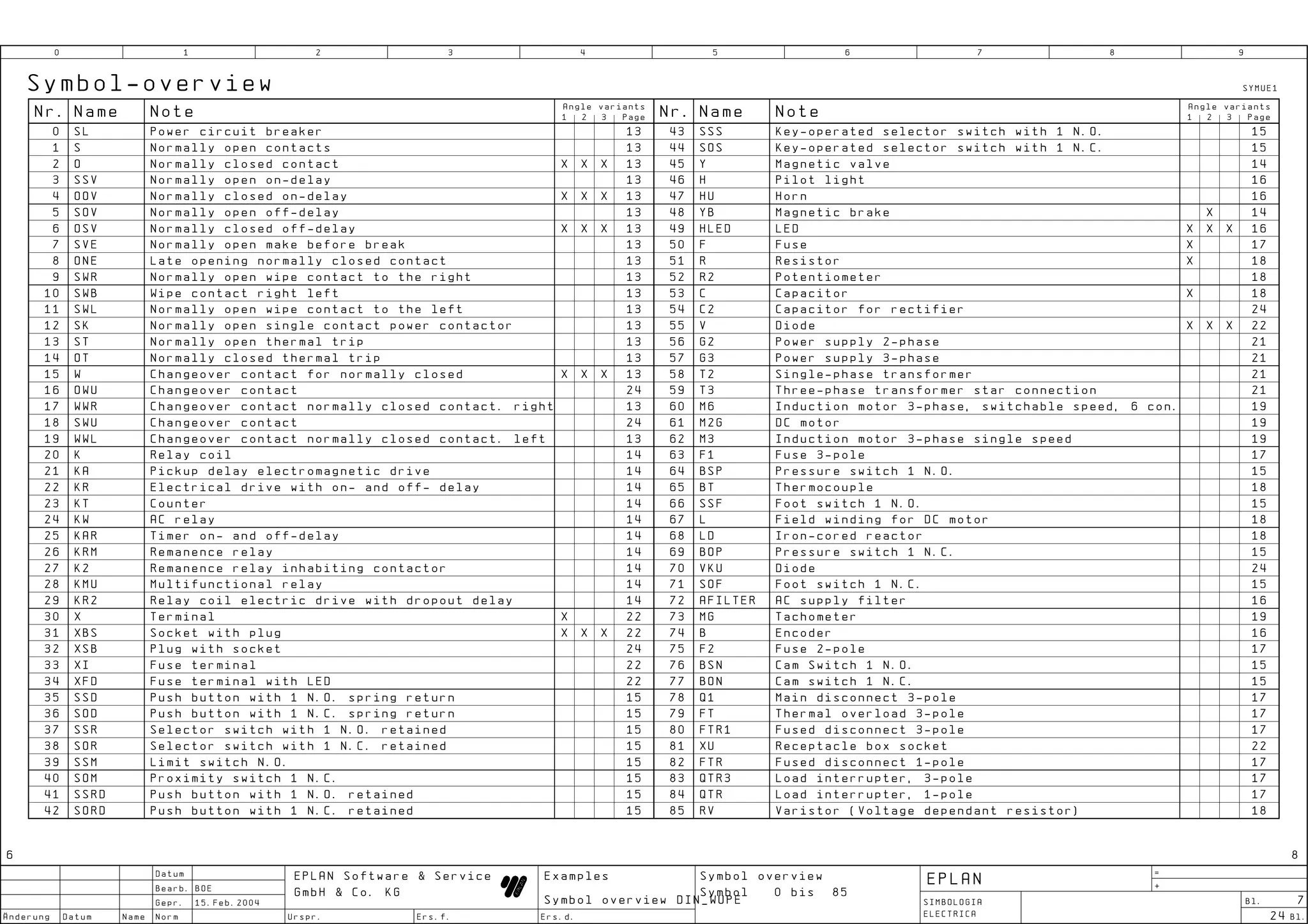
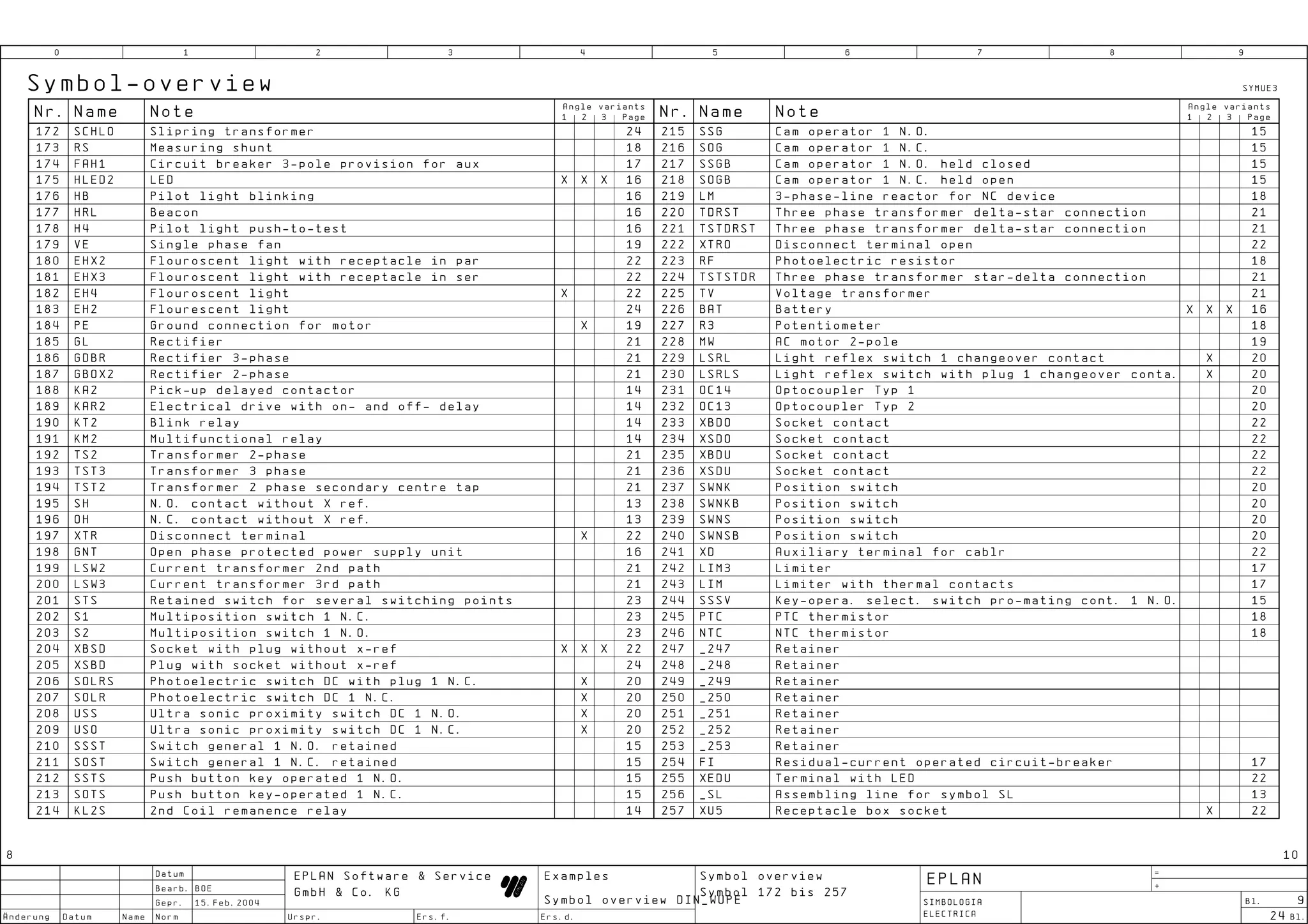
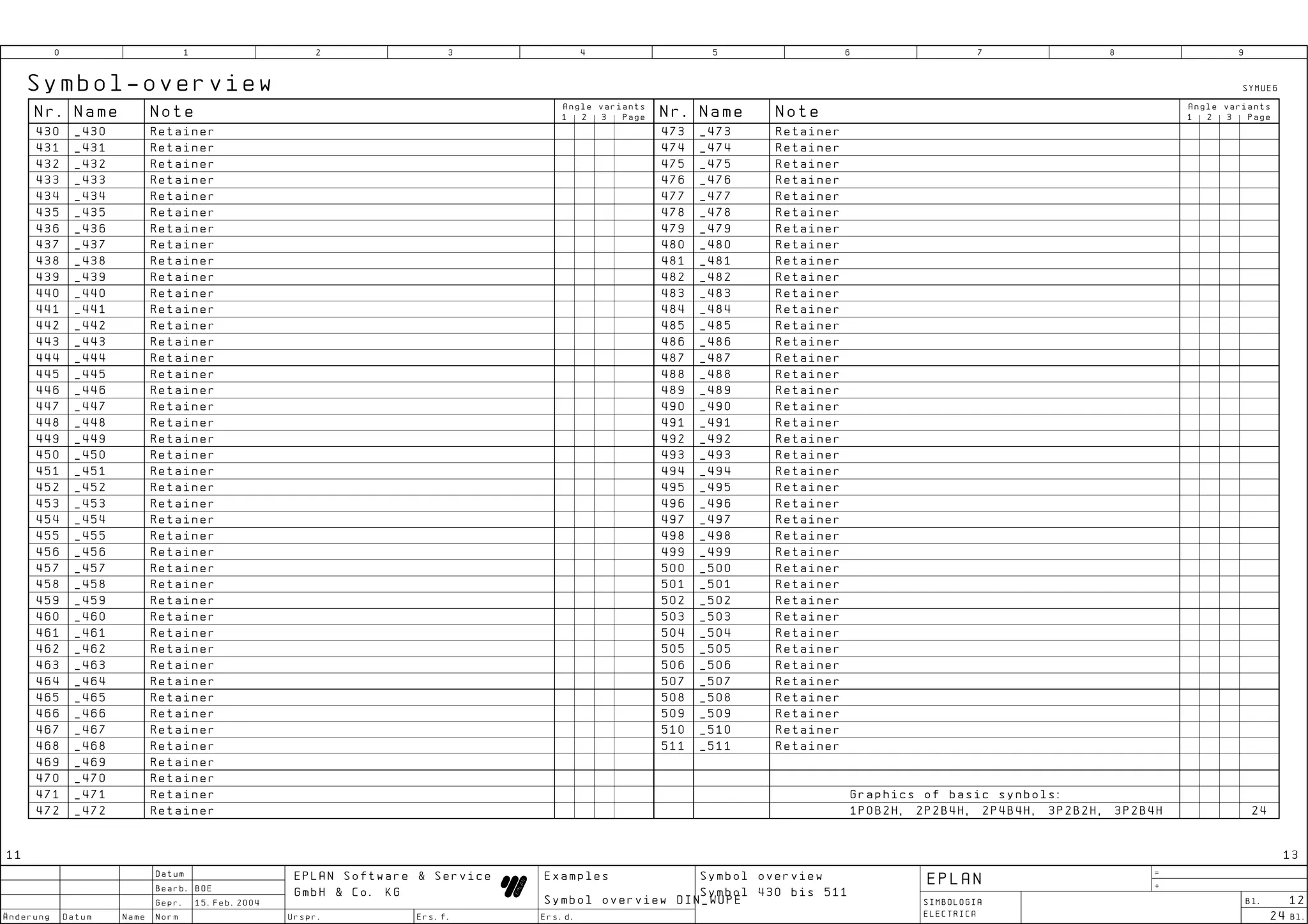
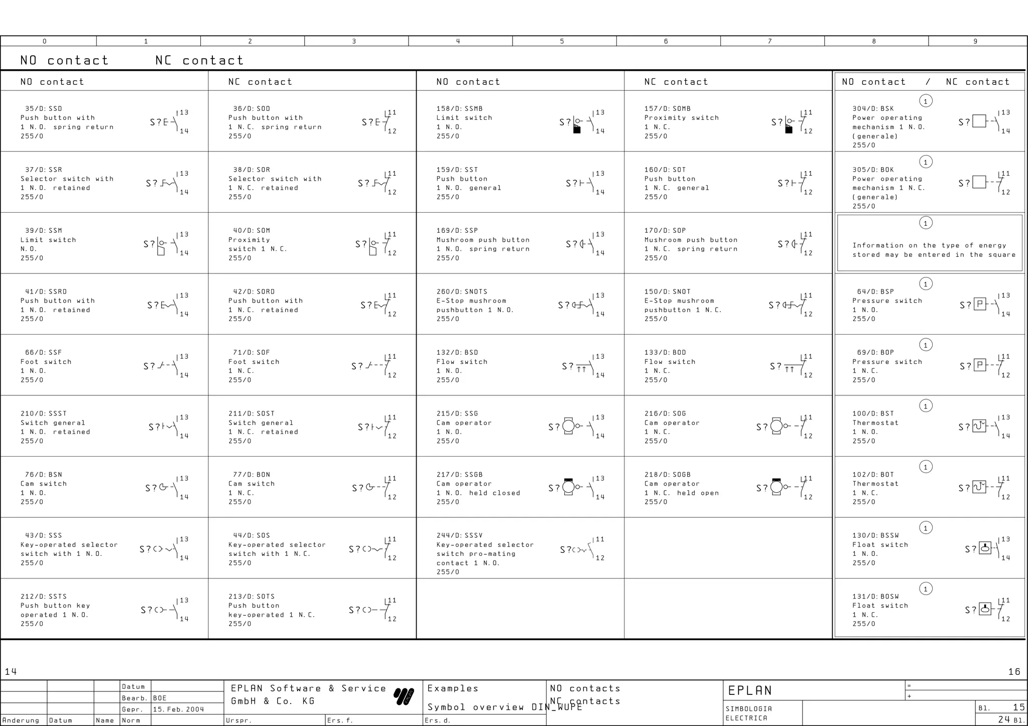
This document provides a symbol overview from a project file for an electrical control system. It includes a title page with project details, a page overview listing the pages and their designations in the file, and a symbol overview table showing electrical component symbols numbered from 0 to 511 along with their names and notes. Modification pages also document changes made to symbols in prior versions of the file by date and editor. The document aims to indicate the structure and content of the symbol file for the DIN_WUPE electrical standards.


