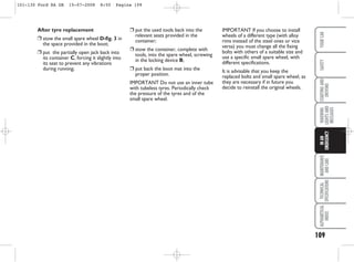
The document is an owner's handbook for a Ford Ka that provides information about:
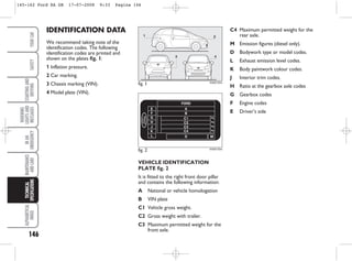
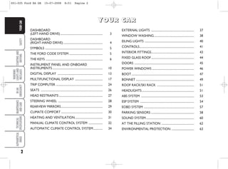
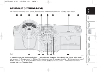
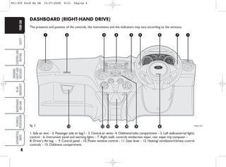
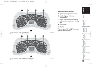
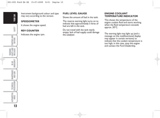
1. The dashboard layout and controls for left and right-hand drive versions.
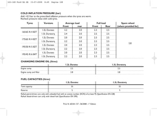
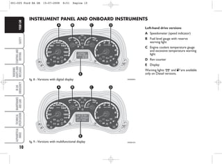
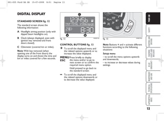
2. Instrument panel displays including the speedometer, fuel gauge, temperature gauge, and odometer/trip computer.
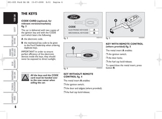
3. Ignition switch positions and remote key functions.
It offers descriptions of features and instructions for operating vehicle systems to familiarize owners with the vehicle.

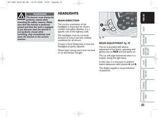


![110
WARNING
LIGHTS
AND
MESSAGES
MAINTENANCE
AND
CARE
TECHNICAL
SPECIFICATIONS
ALPHABETICAL
INDEX
YOUR
CAR
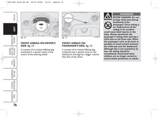
SAFETY
STARTING
AND
DRIVING
IN
AN
EMERGENCY TYRE REPAIR KIT
Your vehicle may not have a spare tyre.
In this case it will have an emergency
tyre repair kit that can be used to
repair one flat tyre.
The tyre repair kit is located in the
spare wheel well.
GENERAL INFORMATION
Depending on the type and
extent of tyre damage,
some tyres can only be partially
sealed or not sealed at all. Loss of
tyre pressure can affect vehicle
handling, leading to loss of vehicle
control.
WARNING
Do not use the tyre repair
kit if the tyre has already
been damaged as a result of being
driven under inflated.
WARNING
Do not try to seal damage
other than that located
within the visible tread of the tyre.
WARNING
Do not try to seal damage
to the tyre’s sidewall.
WARNING
Compressed air can act as
an explosive or propellant.
WARNING
Never leave the tyre repair
kit unattended while in use.
WARNING
Do not keep the compressor
operating for more than
10 minutes.
WARNING
The tyre repair kit seals most tyre
punctures [with a diameter of up to six
millimetres (1/4 inch)] to temporarily
restore mobility.
Observe the following rules when using
the kit:
❒ Drive with caution and avoid
making sudden steering or
driving manoeuvres, especially if
the vehicle is heavily loaded or you
are towing a trailer.
❒ The kit will provide you with an
emergency temporary repair,
enabling you to continue your
journey to the next vehicle or tyre
dealer, or to drive a maximum
distance of 200 kilometres (125
miles).
❒ Do not exceed a maximum speed
of 80 km/h (50 mph).
❒ Keep the kit out of the reach of
children.
❒ Only use the kit when the ambient
temperature is between –30°C (-
22°F) and +70°C (+158°F).
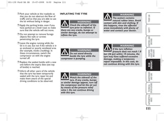
USING THE TYRE REPAIR KIT
Note Use the tyre repair kit only for
the vehicle with which it was supplied.
101-130 Ford KA GB 15-07-2008 8:50 Pagina 110](https://image.slidesharecdn.com/enusacg3549kaaog200807-230811193053-228369e2/85/ENUSA_CG3549_KAA_og_200807-pdf-111-320.jpg)