The illustrations, technicalinformation, data and descriptions contained in this publication, were correct at the time of going
to print. We reserve the right to make any changes necessary in line with continuous development and improvement/
This publication may not be duplicated, reprinted, stored in a data processing system or transmitted by electronic,
mechanical, photographic or other means, or recorded, translated, edited, abridged or expanded without prior written
consent of Ford Otomotiv San A.S. The same also applies for parts of this manual and their use in other applications.
Although due care has been taken to make it as complete and accurate as possible, it can stilll be subject to alterations.
This publication describes options and trim levels available throughout the Ford model range in every country, and therefore
some of the items covered may not apply to your vehicle.
Important: Ford genuine parts and accessories have been specifically designed for Ford vehicles. They are dedicated for
your Ford vehicle.
We would like to point out that other parts and accessories than mentioned above have not been examined and approved
by Ford unless explicitly stated by Ford. In spite of continuous market product monitoring, we cannot certify the suitability
of such products. Ford is not liable for any damage caused by use of such products.
Issued by Ford Otomotiv San. A.S., Ford Customer Service Division
Copyright 2019
3.
Contents
1
1- INTRODUCTION Braking95 6- SPECIFICATIONS
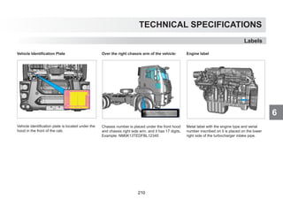
Accessories and Parts 4 Shifting 104 Labels 210
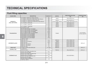
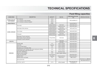
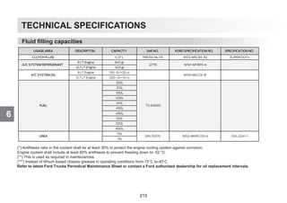
Dashboard 6 Power take off 114 Fluid filling capacities 211
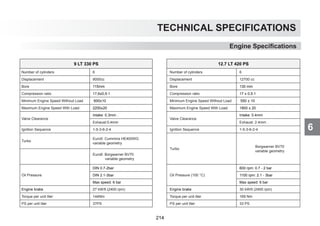
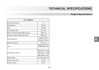
While driving 116 Engine Specifications 214
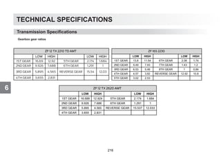
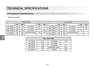
2- SAFETY ECAS Transmission Specifications 216
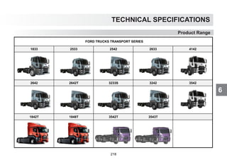
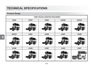
Seat Belts 9 (Electronically Controlled Air Suspension) 119 Product Range 218
Park Brake Control 11 Air Suspension Mechanical Installation of Upper structure 220
Tires and Wheels 12 Level Adjustment 122
General Safety Warnings 14 Tag Axles 123
EBS - ESP 126
3- CONTROLS AND INDICATORS Differential Lock 128
Instrument Panel 18 Lane Departure Warning System 131
Trip Computer 29 Emergency braking system 134
Control Buttons 36 Useful Information 139
Multi-functional Handles 38
Tachograph 41 5- MAINTENANCE AND SERVICE
Attaching and Detaching a Trailer 144
4- OPERATION Fuel Quality and Refueling 154
Opening and closing of the vehicle 49 Cleaning of Exhaust Filter 156
Cab Ventilation 54 Urea System 159
Seats and Beds 55 Tires and Rims 162
In-cab storage compartments 65 Driver Cab 171
Steering 68 Engine 175
Mirrors 69 Steering 186
Lighting 71 Towing the Vehicle 187
Window Washing and Heating Systems 76 Electrical Systems 189
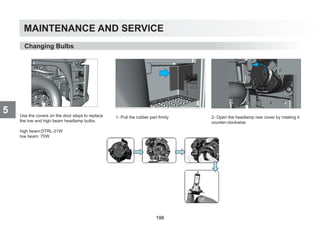
Circuit Breakers 78 Changing Bulbs 198
A/C and Heater 80 Suspension Systems 203
Driving 91 Locations of the Tools in the Vehicle 205
Questions and Remedies 206
4.
About This Manual
ABOUTTHIS MANUAL
Thank you for choosing Ford. We recommend that you take some time to get to know your vehicle by reading this manual.
The more that you know about it, the greater the safety and pleasure you will get from driving it.
Also some features may be explained although they are not introduced because of the time periods between the dates of issue.
Regular servicing of your vehicle helps maintain both its roadworthiness and its resale value.
More than 100 Ford Authorized Dealerships around the world will offer you help with their professional service experience.
Authorized Dealerships provide you the best expert service with their specifically trained personnel. Moreover, they are supported with a wide range
of tools and equipment specially developed for applying service on Ford vehicles.
Note: Remember to pass on the Owner’s manual when reselling the vehicle. It is an integral part of the vehicle.
All technical information and data included in this manual are valid in the issue date of this manual. However, we reserve the right to make changes
without prior information due to our continuous product development policy as FORD OTOSAN.
Some features described in the user handbook may not be present in your vehicle depending on the vehicle model.
Regards,
FORD OTOMOTİV SANAYİ A. Ş.
For Diesel Vehicles
CAUTION !
Use only EN590 compliant, high quality fuel (Eurodiesel) with low ratio of sulphur. Faults that may be caused by the failure to use EN590 compliant,
high quality fuel (Eurodiesel) with low ratio of sulphur shall be considered out of warranty cover. Fuel-related faults that may occur when EN590
compliant, high quality fuel (Eurodiesel) with low ratio of sulphur is not used shall be considered out of warranty cover.
FORD OTOSAN
2
1
INTRODUCTION
PARTS AND ACCESSORIES
YourFord has been built to the highest
standards using high quality Ford Original
Parts. You may enjoy driving your vehicle for
years.
We advise you to use Ford Original Parts only
when an unexpected situation occurs and a
part should be replaced.
The use of Ford Original Parts ensures that
your vehicle is repaired to its pre-accident
condition and maintains its maximum residual
value.
Ford Original Parts complies with the strictest
safety conditions and highest safety standards
of Ford. Thus, they offer the best total repair
cost including the costs of parts and labour.
Now it is much easier to understand if the part
offered to you is a Ford Original Part. Ford
Original Parts listed below have a Ford logo on
them. Inspect whether the part has a Ford logo
in case of a repair, and make sure that Ford
Original Parts are used.
Symbols on your vehicle
When you see these symbols, refer to the
relevant section of this manual before touching
any part or attempting an adjustment of any
kind.
SYMBOLS GLOSSARY
Symbols in this manual
WARNING
You risk death or serious injury to yourself and
others if you do
CAUTION
You risk damaging your vehicle, if you do
not follow the instructions highlighted by the
caution symbol.
Accessories and Parts
4
7.
1 INTRODUCTION
ACCESSORIES, PARTSAND MODIFICATIONS ON YOUR FORD TRUCKS VEHICLE
Today, there are many non-original parts and accessories are being sold in the market for FORD TRUCKS vehicles. Using these types of non-
original FORD TRUCKS parts and accessories (even these parts are authorized by some institutions in your country) may have an adverse effect
on the safety of your vehicle. Therefore, non-original FORD TRUCKS parts and accessories and problems likely to result from the usage of these
are not considered under warranty and this does not put FORD TRUCKS under any liability.
No modifications should be performed on this vehicle. Any modification on your FORD TRUCKS could effect your vehicle’s performance,
safety, and durability, and it might also be against legal regulations. Additionally, any damage and performance problems due to the modification
of your vehicle are not considered under warranty cover.
FORD OTOMOTİV SANAYİ A. Ş.
5
Safety
2
Seat belts providedwith your vehicle are the
most important on-board safety equipment.
Seat belts minimize the risk of injury by
reducing the movement of the occupants in
the direction of impact and their contact with
the interior in case of a crash.
Always fasten your seat belts while driving.
Seat belt shall not loose or bent or shall not be
blocked by another occupant or load.
WARNING
Seat belt cannot provide its protection function
if you do not fasten it correctly or ensure that
the belt lock is engaged properly. Otherwise,
you may get seriously or fatally injured in case
of an accident. Ensure that all occupants of
the vehicle have properly fastened their seat
belts to prevent this.
CAUTION
While you are fastening your seat belt, ensure
that,
- it does not pass through your belly that it
passes through your hip, e.g. your thighs
- it is tight
- it is not twisted any way
- it passes through the middle of your
shoulders
- it does not pass through your neck or armpits
- it is strained on your hips by pulling it
upwards from the chest .
Do not fasten the belt with heavy items and
avoid wearing thick clothes.
Do not fasten the seat belt over fragile objects
in or on your clothes such as glasses, keys,
pens etc.
Use a seat belt for only one person.
Never travel with your children on your lap and
do not fasten the seat belt over them.
WARNING
Seat belts provide safety inside the vehicle
when the occupants are seated in vertical
position while the backrests of the seat are in
vertical position.
Avoid seating position that prevents correct
operation of the seat belts.
Do not drive while the backrest is leaned
backwards excessively.
Seat Belts
9
12.
Safety
2
WARNING
Seat belt cannotprovide proper functionality
when the belt or lock of the seat belt is
damaged. To prevent this, check the seat
belts for damage or jamming periodically.
Otherwise, seat belt may be torn in case
of an accident and cause serious or fatal
injuries.
Fastening the seat belt
Pull the seat belt continuously from the reel.
Seat belt may be locked when it is pulled too
fast or when the vehicle is on a slope.
In this case, relieve the seat belt and allow it to
retract a little, then try again.
Hear the locking click when you are inserting
the latch of the seat belt to the buckle.
Otherwise, seat belt is not locked.
Press the red button on the buckle to release
the seat belt. Then, release the belt slowly to
allow that it is wound on the reel fully.
Seat belt shall pass through the middle of your
shoulder. And, the waist part shall be seated
firmly on your hips, not on your stomach.
Seat Belts
10
13.
Safety
2
WARNING
Park brake isspring type. If there is not
enough pressure in the air tanks, park brake
will not be released from the control lever.
There shall be enough air pressure on the
tanks to release the brake. If there is not
enough pressure, the brake can be release
by turning the setting mechanism of the
adjustment bolt located on the park brake
bellows.
Before releasing the park brake spring,
ensure the safety of your vehicle by
chocking the wheels. Do not drive the
vehicle if any park brake circuits are not
working.
Bellows may be frozen if the brakes cannot
be released while the lever is released on
winter. Spring is shrunk by rotating the
bellows installation bolt in the tightening
direction. To ensure that the emergency
spring is fully installed, installation bolt shall
be tightened until it does not turn anymore.
Park Brake Control
Park brake is placed on the front console.
Always apply the park brake after parking the
vehicle. Chock the tires if the vehicle is parked
on a slope.
Park position:
Bring the park brake lever to 1 position.
Red
P
illuminates on the indicator when
the park brake is applied.
• TEST POSITION:(TRACTOR VEHICLES)
After taking lever to
position 1, check whether the vehicle with
semi-trailer moves by pressing on the
lever and pulling the lever down (position
3). Then, bring the lever to park position
(position 1) again.
• Then, get off the vehicle and apply the trailer
park brake.
Drive position:
Bring the park brake lever to 2 position.
WARNING
Do not apply the park brake while the brake
drums or disks are very hot, wait for them
to cool.
11
14.
Safety
2
One of themost important safety elements
on your vehicle is the tires. Check the tire
pressure and condition periodically. Do not
drive your vehicle with worn tires. -When
the tire pressure is very low, tires may get
extremely heated, worn and these may cause
excessive fuel consumption.
-When the tire pressure is very high, this may
cause longer braking distance, worse handling
and excessive wear on tires.
-If the pressure loss happens continuously, this
may be caused by external damages, cracks,
foreign material in the tires and faulty tire
valves leaking air.
WARNING
Please, observe the prescribed tire pressure
for your vehicle.
Very low tire pressure may cause blow-out
of the tire at high speeds and loads. You can
cause an accident and thus injuries to others
due to this.
Tire profiles
A minimum profile depth is prescribed for tires
by law. Observe the legislation for the relevant
country.
For safety reasons, change your tires before
reaching the legally advised minimum profile
depth.
WARNING
An excessively low tire profile may cause
loss of handling at high speeds in case of
rain or snow mud conditions. You may loose
your handling and cause an accident in
these conditions.
The Condition of the Tires
Check the following conditions regularly every
2 weeks and before a long haul to inspect the
condition of the tires:
- External damage
- Cracks and bulges on the tires,
- Foreign material in the tire profile,
- Irregular wear of the profile.
WARNING
Do not forget that the external damages,
bulges and cracks on the tires may cause
blow-out of the tire. You may cause an
accident in these conditions.
Tires and Wheels
12
15.
Safety
2
Tires and Wheels
TheAging of the Tires
- Aging of the tires reduces the operation and
traffic safety of the tires. Even unused tires are
aged.
- Always replace your tires if they are aged
more than 6 years.
Tire Damages
Tire damages are usually caused by the fol-
lowing reasons:
- Aging of the tire
- Foreign material
- Usage conditions of the vehicle
- Weather conditions
- Oil, fuel, grease etc. Contact with materials
- Dragging on the sidewalks
- Low or high tire pressure
WARNING
When your vehicle passes over the sides of
the sidewalks or objects with sharp edges,
this may cause damages that cannot be
seen externally.
These damages can only be noticed in the
future and cause a flat tire.
Do not park your vehicle with some part of
the tire on the sidewalk.
13
16.
Safety
2 General SafetyWarnings
WARNING
Failure to observe following conditions may
cause accidents which may result in serious
injuries.
- Using a mobile phone while driving may
distract you.
- Do not adjust the seat and steering wheel
while driving.
- Occupants travelling on any other place
than seats (e.g. on the bed) may cause seri-
ous injuries while braking.
- Do not put any objects on the beds inside
the cab; this may cause serious injuries
while braking.
WARNING
Make sure the heater is off before refuelling
of the vehicles with additional fuel tank for
additional cab heater.
WARNING
Do not carry or store material harmful to the
health inside the driver cab.
Examples of these materials are:
- Fuel
- Acid
- Lubricants and grease
- Cleaning agents
Vehicle Tracking Safety System
Fleet tracking systems are also used for find-
ing the location of the vehicle in case of car
theft. However if the vehicle tracking module
is removed, the location of the vehicle cannot
be found.
Vehicle Tracking Safety System eliminates this
problem which is the weak point of the fleet
tracking systems, since the module cannot be
removed and prevents the stolen vehicle from
being driving away.
In vehicles with optional vehicle tracking safety
system, starting may be last up to 35 sec-
onds when the disconnecting switch shut off
because of the safety package.
After the ignition is on, wait for the red immobi-
lizer light to dim out before starting.
Vehicle tracking safety system warning indica-
tor
If the instrument panel and FMS cannot com-
municate while the ignition is on, the vehicle
cannot be started.
This prevents the starting of the vehicle with-
out GPS tracking.
Vehicle cannot be started and indicates a
warning in this case.
WARNING
Items that you may place on the toolbox
compartment shall not exceed 8 kg. Also,
precautions shall be taken against the risk
of items moving and damaging the toolbox
compartment when the vehicle is moving.
14
17.
Safety
2
CAUTION
When there arepersonnel on the step at
the rear of garbage trucks, vehicle speed
is limited to 30 km/h and vehicle can not
reverse.
General Safety Warnings
The “ERA” mode:
Backlight of buttons “SOS”,”Service” – white light
The “Emergency Call” Mode:
Backlight of button “SOS” – red light,
Backlight of button “Service” – white light.
Backlight of the LED:
-Switching on – red light 5 sec, then green flashing;
-The “ERA” mode – green light;
-Data transfer in the “Emergency Call” mode – green light;
-Malfunction – red light.
1- Service Buton
2-Microphone
3-Protective cover
4-SOS Buton
5-Led
ERA-Glonass
Cleaning of Exhaust Filter
The exhaust filter found in Euro 6 vehicles
retains the smut coming from the exhaust gas
and decreases the emission values. With the
exhaust filter cleaning operation which can be
performed automatically or manually, the smut
retained in the filter is burned with regular
intervals so that the filter is emptied before
filling up and being clogged. In this operation,
the exhaust gas is heated by the engine and
smut is burned. Driver is informed about the
exhaust filter cleaning of the vehicle through
the messages displayed on the indicator panel
and explained in detain in the Exhaust Filter
Cleaning section
Since the exhaust gas shall heat up during the
exhaust filter cleaning; ensure that the vehicle
is not in the same place with flammable,
inflammable and explosive materials or in
enclosed space
Ensure that vehicle exhaust cleaning is not
performed in locations like hazardous material
loading and unloading places or fuelling
stations. When necessary, activate the exhaust
filter cleaning prevention using exhaust filter
cleaning prevention button
Using exhaust filter cleaning prevention for
prolonged time may cause the exhaust filter to
be clogged and rendered unusable. Please
observe the warnings provided in the indicator
panel and do not use manual filter cleaning
prevention unless necessary.
15
CONTROLS AND INDICATORS
3FUNCTION SYMBOL COLOR CONTROL BUTTON BUZZER
Left Signal Lamp Green
Multi-functional handle (left) yes
Right Signal Lamp Green
Low brake air pressure Red Instrument yes
EBS Red / Amber Automatic n/a
ABS Amber Automatic n/a
High Beam Blue Multi-functional handle (left) n/a
Alternator Red Automatic n/a
Park Brake Sign Red Park brake control n/a
Cab Lock Sign Red Cab lifting mechanism yes
Instrument Panel
19
22.
CONTROLS AND INDICATORS
3
InstrumentPanel
FUNCTION SYMBOL COLOR CONTROL BUTTON BUZZER
Oil Pressure Warning Red Automatic yes
Cold Starting Aid Amber Automatic n/a
Height Engine Water
Temperature
Red Automatic yes
Trailer ABS/EBS Amber Automatic n/a
Trailer right/left turn
signal warning
Green Multi-functional handle (left) n/a
Engine Warning Lamp Amber Automatic n/a
Cruise Control Green Multi-functional handle (right) n/a
Front Fog Lamp Green Headlamp switch n/a
20
23.
CONTROLS AND INDICATORS
3FUNCTION SYMBOL COLOR CONTROL BUTTON BUZZER
Rear Fog Lamp Amber Headlamp switch n/a
Fuel Level warning Amber Automatic n/a
Air Pressure 1 Green
Air pressure control button on the indicator n/a
Air Pressure 2 Green
Seat belt warning red Automatic yes
ESP Amber control button on the control panel n/a
Immobilizer Red Automatic n/a
MIL (malfunction
indicator lamp)
Amber Automatic n/a
Instrument Panel
21
24.
CONTROLS AND INDICATORS
3
InstrumentPanel
FUNCTION SYMBOL COLOR CONTROL BUTTON BUZZER
Intarder Amber Automatic n/a
Oil level warning Red Automatic n/a
Engine brake Amber Multi‐functional handle (right) n/a
Information warning Amber Automatic n/a
Lane departure warning system Amber Control button on the control panel yes
Emergency braking system Amber Control button on the control panel yes
Icing warning Red Automatic n/a
Park lamp indicator warning Green Headlamp switch n/a
Exhaust Filter Cleaning Green Automatic n/a
High Exhaust Temperature Amber Automatic n/a
Amber Control button on the control panel n/a
ESP OFF
22
25.
CONTROLS AND INDICATORS
3
25
CONTROLSAND INDICATORS
3
Instrument Panel
Instrument Panel
Display warnings and error warnings.
SYMBOL WARNING W ARNING DESCIRPTION
Drive with fixed speed to
clean exhaust filter
Exhaust smut filter saturation is above the expected level. This might be caused by the style of driving or the driving time. For the vehicle to be
able to conduct automatic filter cleaning, it is advised that you drive the vehicle with a fixed speed above 30kph when you see the green exhaust
filter cleaning symbol. If the road conditions are not suitable, it is recommended to perform manual exhaust filter cleaning.
Park the vehicle. Perform
exhaust filter cleaning
using the button
Exhaust smut filter is filled to the extent that the vehicle cannot perform automatic cleaning. In this case; park the vehicle to a safe location and
make sure that the vehicle is not in contact with any flammable material, and then perform manual cleaning using the manual cleaning button. You
can find manual cleaning conditions in the manual exhaust filter cleaning section.
Exhaust filter excessively
full. Drive to a workshop.
Exhaust smut filter is filled to the extent that the vehicle cannot perform manual or automatic cleaning. In that case; it is recommended that you
immediately drive to the nearest service and have the exhaust smut filter cleaned before it is damaged. Drive vehicle under light load to prevent
excessively full exhaust filter from being damaged.
Remove the cancellation
of exhaust filter cleaning
when possible
Exhaust filter started to fill up excessively while the manual exhaust filter cleaning prevention is active. It is recommended that you lift the exhaust
filter cleaning prevention before the filter is overloaded or allow manual filter cleaning. You can remove the filter cleaning block by keeping the filter
cleaning prevention button for 3 seconds or shutting off and restarting the engine.
Exhaust filter is being
cleaned.
Remainder: X minutes
Manual exhaust filter cleaning is active During exhaust filter cleaning, the exhaust gas temperature is increased to burn the soot inside the exhaust
filter. Time remaining to the end of operation is shown in minutes.
Conditions are not
suitable for cleaning of
the exhaust filter
Conditions are not suitable for manual exhaust filter cleaning. In this case, you have to ensure that the conditions written in the manual exhaust
filter cleaning section are met
Exhaust filter is not being
cleaned. Drive to a
workshop.
An error in the vehicle or the exhaust system automatically prevents the vehicle from performing exhaust filter cleaning. In this case, you should
drive to the nearest service and have necessary checks performed. Otherwise, the exhaust filter will fill excessively and be damaged.
Exhaust filter cleaning
prevented by the driver.
Exhaust filter cleaning prevention is activated by the driver. You can activate the exhaust filter cleaning prevention while loading hazardous
materials or while driving the vehicle in an environment with flammable materials like grass, hay, petroleum products etc. Please keep in mind that
the exhaust filter will be damaged in long blocking durations.
Exhaust gas is hot, pay
attention during parking.
This warning is for the purpose of informing the driver. Exhaust gas temperature is high due to driving under heavy load or exhaust filter cleaning.
This warning is activated when the exhaust gas temperature is high and the vehicle speed is low. It is normal to see this warning during exhaust
filter cleaning. When the warning is active, please ensure that the vehicle and exhaust fumes are not in the same environment as flammable
materials like grass, hay, petroleum products etc. and that the vehicle is not in an enclosed space. Otherwise, fire risk may occur!
Defective
Urea detected
Material not conforming to ISO22241-1 standards detected in urea tank. Please discharge the urea tank and add urea conforming to standards.
Please remove the error to prevent power cut off.
23
26.
CONTROLS AND INDICATORS
3
InstrumentPanel
SYMBOL WARNING WARNING DESCIRPTION SYMBOL WARNING WARNING DESCIRPTION
Depress the
clutch pedal.
Change the gear lever to neutraland
depress the clutch pedal tostart the
engine.
Rear axle did not raise.
Rear axle did not raise. First raise the front
axle.
N/A AEBS failure AEBS failure, drive to workshop
Rear axle did not
lower.
Rear axle did not lower. Vehicle speed is
high
N/A Radar obstructed Front radar sensor is obstructed.
Front axle did not
raise.
Front axle did not raise. Vehicle loaded.
N/A Front camera failure Front camera failure,drive to workshop
Front axle did not
raise.
Front axle did not raise. Vehicle speed is
high
N/A low camera resolution low camera resolution.Clean the screen.
Front axle did not
lower.
Front axle did not lower.Vehicle unloaded
Rear axle did not raise. Rear axle did not raise.Vehicle loaded.
Front axle did not
lower.
Front axle did not lower. Vehicle speed is
high
Rear axle did not raise.
Rear axle did not raise.
Vehicle speed is high
Front axle did not
lower.
Front axle did not lower, first lower the rear
axle.
Rear axle did not raise. Rear axle did not raise. Handbrake applied.
Rear axle did not
lower.
Rear axle did not lower. Vehicle loaded.
Trailer brake system
problem
AEBS do not support
trailer brake system
LIM
30 km/h
Speed Limit
Speed limiter will be
active after 60s
Tachograph Break
Time
4.5 hours driving time
is over Give a break
40 km/h Overspeed Warning
40 km/h speed exceeded
Slow down
Lifting Damper Active Lifting Damper Active Battery failure Battery failure, drive to service.
24
27.
CONTROLS AND INDICATORS
3
InstrumentPanel
SYMBOL WARNING WARNING DESCIRPTION
SYMBOL WARNING WARNING DESCIRPTION
Rear axle did not
lower.
Rear axle did not lower.
Handbrake applied.
Oil level warning Add oil to engine
Front axle lowered. Front axle lowered. Vehicle loaded. ECAS Air suspension warning active
Low idle shutdown
Soon press any pedal to cancel
(only manuel transmission vehicles)
oil change warning Engine oil renewing time
VGS active VGS active
Blocked air cleaner
warning
Air cleaner must be changed as soon as
possible. Drive to workshop
Clutch lining failure Warning, clutch overheated
Low steering oil
pressure
Oil level must be controlled when lit. If
there is a leakage, request road
assistance. If there is no leakage, drive to
nearest workshop without exceeding 50
km/h speed.
Clutch lining failure Warning, clutch protection active Fuel filter blocked Drive to workshop
Cab raising active Cab raising active
Low engine cooling
water level warning
Add engine cooling water, if warning
light does not go out, drive to workshop
as soon as possible.
Door open warning One of the doors is open Water in fuel warning
Discharge the water in pre fuel filter
drain, if warning light is still active,
drive to workshop as soon as possible.
Hill holder active Hill holder active
autodrop failure..see
manuel
autodrop failure..see manuel
(page 141)
brake pedal
demand
Brake pedal test shall be performed
(page 120)
Critical emission
error
Error detected in systems related to
emission.Please drive to service to prevent
power cut off.
Urea dosage
error
Error detected in urea dosing system.
Please drive to service to prevent power
cut off.
Refill the urea tank
There is not enough level of urea in the urea
tank. Please add urea that conforms to the
standards in order to prevent power cut off.
Low urea level
Urea level low in urea tank. Please add urea
that conforms to the standards in order to
prevent power cut off.
25
28.
CONTROLS AND INDICATORS
3
Odometer
Indicatesthe road speed (kilometer/hour).
Tachometer
Indicates the engine rpm. Operate your vehicle
so that the indicator dial remains in the green
zone as much as possible.
Drive your vehicle considering the engine
speed. Keeping engine speed in the green zone
provides economy.
Avoid excessive speeds in the red danger zone.
Otherwise, your engine may get damaged.
Ensure that the speed does not increase up to
red danger zone, especially while driving down
the hill.
Green zone: economy zone
Blue zone: zone where engine brake is
activated
Red zone: Danger zone
Buzzer sounds when you exceed the
maximum allowed engine speed. Lower the
engine speed when you hear that warning.
Engine brake is shut down over of 2400 rpm.
Instrument Panel
12.7Lt vehicles
9 Lt vehicles
26
29.
CONTROLS AND INDICATORS
3
Enginecoolant temperature gauge
Indicates engine coolant temperature.
If the dial of the indicator is in the red area,
engine may overheat.
Red warning light is illuminated on the
indicator, and the buzzer sounds at 110 °C on
vehicles with regulated air compressor. Red
warning light is illuminated on the indicator,
and the buzzer sounds at 104 °C on vehicles
with non-regulated air compressor. Torque
reduction values : 110 °C in vehicles with
adjustable air compressor, 104 °C vehicles
without adjustable air compressor.
Perform the following when the red warning
lamp is illuminated:
• Stop the vehicle and operate the engine in
idle.
• Apply park brake, check for water leaks
under the vehicle (do not get under the
vehicle.) check from the side.)
• Open the hood and check for the water level
in the engine auxiliary water tank.
• If the water temperature does not drop, stop
the engine and tilt the cab. Inspect whether
the engine belt is broke.
• Check for water leaks in the thermostat area
on the front of the engine.
• Ask the support of a Ford Trucks authorized
dealership, if required.
Fuel gauge
Indicates the fuel level in the tank.
0: empty
½: half full
1: full
Amber warning lamp indicates low fuel level
in the tank. Refill fuel immediately. System will
take air if the fuel is lowered.
Icing Warning
Icing warning lamp will light up if
outside temperature is between
0 and 4 degrees. If the outside
temperature is below 0 degrees, icing
warning lamp will blink with short
intervals.
Instrument Panel
27
30.
CONTROLS AND INDICATORS
3
Airpressure indicator
There are 2 independent air system circuits
that supply for the front and rear brake
systems. You can read the pressures of these
systems from a single air pressure indicator.
Indicator shows the pressure value of the line
with low pressure automatically.
If the indicator 1 indicates the circuit air
pressure, light is illuminated.
If the indicator 2 indicates the circuit air
pressure, light is illuminated.
Air pressure indicator always shows the air
pressure of the circuit with the lowest air
pressure. Press the button on the indicator if
you would like to view the air pressure of the
other circuit. Indicator will display the pressure
of the circuit with the lowest air pressure
automatically after a specified time.
Normal operating pressure of the system is
10.5 bars.
If any warning is displayed on the screen, the
key on the instrument shall lose the function for
tank selection as it will be used for conforming
these warnings. If you would like to view
the 2nd tank, you can do this by moving to
another page from the information page.
Air pressure audible warning
If the air pressure goes below 6.5 bars, low
pressure audible warning will be activated.
Buzzer is turned off when system pressure
reaches the normal operating pressure at both
pressure circuits.
Do not drive your vehicle before the audible
warning is deactivated!
If you hear the audible warning while driving
stop your vehicle immediately. Block the
wheels. Place road safety signs and call a
Ford Trucks authorized dealer.
Oil pressure indicator
Indicates engine oil pressure in bars.
Oil pressure varies depending on the oil
temperature and engine speed.
Operating pressure: 3 bar @ 90 °C, 2500rpm
Idle pressure: 1.5 bars @ 90 °C, 550rpm
The warning lamp will be illuminated when the
oil pressure is low.
Perform the following when the red warning
lamp is illuminated:
• Park the vehicle in a secure place, stop the
engine.
Contact a Ford Trucks authorized dealership.
Instrument Panel
28
31.
CONTROLS AND INDICATORS
3
TripComputer
SYMBOL
DESCRIPTION Prove out Summary
It is recommended to you
to drive to an authorized
workshop in this case.
29
32.
CONTROLS AND INDICATORS
3
TripComputer
SYMBOL
DESCRIPTION
1-Mileage
2-Engine operating hours
Engine total operating hours
1-Average speed
2-Distance that may be
covered
with the remaining fuel
30
33.
CONTROLS AND INDICATORS
3
TripComputer
SYMBOL
DESCRIPTION
1-Instantaneous fuel
consumption
2-Average fuel consumption.
Oil level Functions
31
34.
CONTROLS AND INDICATORS
3
TripComputer
SYMBOL
DESCRIPTION Language Selection
Remaining brake lining
percentage is displayed
for each wheel.
Oil status indicator
32
CONTROLS AND INDICATORS
3
Tripcomputer shows information and
warnings.
Trip computer may be changed by pressing
the menu button on the right multi-functional
lever.
WARNING
As changing trip computer display settings
while driving may adversely affect the driving
attention, it may cause serious
risk of accident. Settings shall always be
performed
while the vehicle is parked.
You may reset trip computer information,
which are allowed to be reset, by pressing
the button on the lower right of the instrument
panel.
Trip Computer
Note: The screen display for the information
that will be reset shall be selected via the
menu button on the right multi-function arm.
35
CONTROLS AND INDICATORS
3
Somefeatures may not be available depending on the vehicle version.
Control Buttons
RESİM NO SEMBOL AÇIKLAMA RESİM NO SEMBOL AÇIKLAMA
1 A/C ON/OFF 13
2 RECIRCULATION 14 SEMI-TRAILER BRAKE
3 MIRROR HEATING 15 REAR AXLE LIFTING
4 WINDSHIELD HEATER 15 FRONT SUSPENSION CONTROL BUTTON
5 ASR CANCEL/ ASR ACTIVE 15 TAG AXLE LIFTING II SWITCH
5 ASR CANCEL/ ASR ACTIVE 16 DIFFERENTIAL LOCK
6
POWER
ROCKING
AUTOMATIC TRANSMISSION MODE SELECTION 17 FRONT AXLE LIFTING
6
OFF-ROAD
ROCKING
AUTOMATIC TRANSMISSION MODE SELECTION 17 INTERMEDIATE SHAFT LOCKING
7 AUTOMATIC HYBRID BRAKE 17 FRONT SUSPENSION LIFTING
8 HILL LAUNCH ASSIST 17 TRACTION HELP SWITCH
9 DIESEL PARTICULATE CLEANING ACTIVE 18 TIPPER LIFTING
9 DOME LAMPS (OPT) 19 EMERGENCY BRAKING SYSTEM
10 DIESEL PARTICULATE CLEANING DEACTIVED 20 LANE DEPARTURE WARNING SYSTEM
10 SIREN BUTTON (OPT) 21 WARNING SWITCH HAZARD FLASHER
11 ROOF ON/OFF 22 ELECTRICAL CIRCUIT BREAKER (OPT)
12 INTERIOR LIGHTING 23 HANDBRAKE
TRAILER AXLE LIFTING
37
40.
CONTROLS AND INDICATORS
3
Multi-functionalhandle (left) It is placed on the left side of the steering.
Switch positions are as follows.
1. Horn
2. Right Direction Indicator
3. Left Direction Indicator
4. Windshield Water Spray
5. Wipers
5a. Wipers off
5b. Low speed wiping (long interval)
(This position activates the automatic wiper
function on vehicles with a rain sensor.)
5c. Normal speed wiping
5d. High speed wiping
6a- High Beam (Flasher)
Flasher is operated by pulling the handle
briefly and releasing it.
6b- High Beam (Continuous)
High beam is operated continuously when the
handle is released after being pulled at full
stroke.
Multi-functional Handles
38
41.
CONTROLS AND INDICATORS
3
Multi-functionalhandle (right)
It has 5 steps in vehicles with Intarder.
It has 2 steps in vehicles without Intarder.
This handle has the following functions:
• Cruise control, increasing the speed, and
decreasing the speed
• Engine brake and Intarder
1- Activation of the cruise control and
increasing the speed
2- Decreasing the speed
3- Deactivation of the cruise control
4- Activation of the engine brake
5- Resuming cruise control
On vehicles without Intarder
2 step engine brake
Engine Brake
1. Range Low Brake Power
2. Range High Brake Power
1 step engine brake
1st stage 100% engine brake
in addition while it is in 0 position, blending
function is used in the vehicles with ebs.
Multi-functional Handles
39
42.
CONTROLS AND INDICATORS
3
Multi-functionalHandles
Vehicles with Intarder:
Activation of the gradual continuous
braking operations
Bring the gradual braking lever from 1 to max.
position.
The vehicle is continually decelerated
according to the selected position.
Position 1 = low deceleration
Max. position = more deceleration.
Deactivation of the gradual continuous
braking operations
• Gradual brake lever:
• OFF position or position 1 = BREMSOMAT
function.
Engine Brake Intarder
Bremsomat Reduced Brake Power Bremsomat (0%-100%)
Intarder 1 Reduced Brake Power 25% Max. Brake Power
Intarder 2 Reduced Brake Power 50% Max. Brake Power
Intarder 3 High Brake Power 75% Max. Brake Power
Intarder 4 High Brake Power 100% Max. Brake Power
40
43.
CONTROLS AND INDICATORS
3
CONTROLSAND INDICATORS
3
Tachograph
Operational elements
(1) Display
(2) Menu buttons
/ Select function / selection
Confirm function / selection
Exit, abort menu
(3) Card slot 1
(4) Combination key Driver 1
Setting of activities and ejection
of the driver card
(5) Combination key Driver 2
Setting of activities and ejection
of the driver card
(6) Card slot 2
(7) Cutting edge
(8) Printer drawer
(9) Download interface
(a) Symbol for ADR variant
1
4
3
2
9
5 6 7
8
a
Standard display(s) during trip
왘 Press any menu key, change to the desired display.
(1) Time (with = set local time)
(2) Operational mode
(3) Speed
(4) Activity, driver 1
(5) Card symbol, driver 1
(6) Total odometer
(7) Card symbol, driver 2
(8) Activity, driver 2
(1) Driving time Driver 1 since a valid
break time.
(2) Valid break time , in accordance with
regulation (EU) no. 561/2006.
(3) Time of driver 2; availability time .
The option VDO Counter allows another standard display; for details
refer to the operating instructions.
12:50 75km/h
123456.7km
1 2
4 8
3
5 6 7
(a)
101h21 00h15
202h05
1
3
2 (b)
41
44.
CONTROLS AND INDICATORS
3
25
1
IntroducingYour Vehicle
Indicators
Tachograph
Calling up menu functions
Possible only when the vehicle is stationary!
왘 Use the buttons / to select the desired display.
왘 Use button to call up the main menu.
왘 Use / to select the listed functions step by step.
Print daily value:
왘 [printout driver 1] ... [24h day] ... [25.10.2017] ...
[printout in UTC yes/no]
Enter Out of scope beginning / end:
왘 [entry vehicle] ... [OUT begin] or [OUT end]
Enter Beginning of ferry / train:
왘 [entry vehicle] ... [ ferry/train]
왘 Set the current activity.
Set Local time:
왘 [entry vehicle] ... [ local time] ...
왘 Set Local time in steps of ± 30 minutes.
103h46 00h15
125h57 00h21
12:40 0km/h
123456.7km
201h10 00h36
215h00 00h21
select
language?
call main menu?
UTC 29.09.2017
10:40 +02h00
printout
driver 1
language
english
1. Main menu
... others see operating
instructions
VDOi 9h 2
∆|19h58 10h 1
VDO 00h44
11h00 03h23
Option: VDO Counter, for
details see operating
instructions.
42
45.
CONTROLS AND INDICATORS
3
46
CONTROLSAND INDICATORS
3
Tachograph
Tachograph
Insert paper roll
왘 Press the unlocking surface on the printer panel, the printer drawer
opens.
왘 Pull the printer drawer out of the DTCO.
왘 Insert new paper roll according to the illustration and guide it via the
pulley (1).
왘 Push printer drawer into the printer compartment until it engages.
왘 The printer is ready for operation.
You can start a printout.
Make sure that the paper roll does not become jammed in the
printer drawer and the start of the paper (1) extends beyond the
edge of the printer drawer!
1 2
Messages
(1) Pictogram and plain text of the message
! = Event, example [! driving without card]
x = Fault, example [x sensor fault]
= Driving time warning [1 break!]
Operational note, example [o no paper]
(2) Error code
For further messages and measures refer to the operating instructions.
Acknowledge message:
왘 Press key 2 times, the message disappears.
x1 internal
fault xx
1
2
Times of the driver card(s)
.
(1) Driving time since a valid break
time.
(2) Valid break time , in accordance
with regulation (EU) no. 561/2006.
(3) Driving time over two weeks .
(4) Duration of the set activity.
103h46 00h15
125h57 00h21
1 2
3 4
43
46.
CONTROLS AND INDICATORS
3
Tachograph
Insertdriver card / Manual entries
왘 If necessary, switch on the ignition in case of the ADR variants.
왘 Keep the combination key Driver 1 for more than 2 seconds.
The card slot is opened.
왘 Open the card slot cover.
왘 Insert driver card into the card slot.
왘 Close card slot and push it in.
왘 Follow the menu guidance.
Always keep the card shafts closed – except for the insertion or
removal of your driver card!
Driver 1 who will drive the vehicle inserts his
driver card into slot 1.
16:00 0km/h
Card!
last withdrawal
15.04.17 16:31
1M entry
addition? yes
continue with example:
A / B / C
The set local time 07:35 and the UTC
time 05:35UTC appear (time offset = 2
hours).
The date and time of the most recent card
withdrawal will be displayed in local time
(symbol ).
Please ensure the continuous recording
of the activities on your driver card!
Make manual entries with Yes.
If you do not want to add any activities/rest
periods, select No.
welcome
07:35 05:35UTC
Withdrawal (15.04.2017) Insertion (18.04.2017)
16:31 Local time 07:35 Local time
Example A:
M 15.04.17 16:31
18.04.17 07:35
왘 Press and hold key .
왘 Automatic jump to the last entry field
(minutes blink).
왘 Release button and press it again.
Appears when End country was entered
during the last withdrawal.
왘 Acknowledge entry.
M 15.04.17 16:31
18.04.17 07:35
1M confirm
entry? yes
begin country
:UK
07:36 0km/h
123456.7km = Trip can be started.
44
47.
CONTROLS AND INDICATORS
3
Tachograph
1Mconfirm
entry? yes
M 24.02.09 23:32
25.02.17 00:20
M 24.02.13 23:32
25.02.17 02:30
M 24.02.17 23:32
25.02.17 02:30
M 25.02.09 00:20
25.02.17 02:30
M 25.02.17 00:20
25.02.17 02:30
02:31 0km/h
123456.7km
왘 Set, acknowledge activity .
왘 Set, acknowledge day, hours, minutes.
왘 Set, acknowledge the next activity .
왘 Press and hold key (the minutes
blink).
왘 Release button and press it again.
왘 Acknowledge entry.
Example B: Withdrawal (24.02.2017) Insertion (25.02.2017)
23:32 Local time
00:20 Local time
02:30 Local time
M 14.11.13 12:10
? Begin country
begin country
:UK
1M confirm
entry? yes
Example C: Withdrawal (05.11.2017) Insertion (14.11.2017)
17:50 Local time
18:45
14:00 Local time
12:10
?
M 14.11.17 12:10
? beg. country
M 05.11.17 18:45
? end country
M 05.11.13 17:50
05.11.17 18:45
M 05.11.17 17:50
14.11.17 14:00
14:01 0km/h
123456.7km
M 28.10.11 18:45
? 14.11.17 12:10
M 05.11.17 18:45
14.11.17 14:00
? end country
:UK
? beg. country
:UK
M 28.10.11 17:45
14.11.17 14:00
M 14.11.17 12:10
14.11.17 14:00
Use key in order to ...
– abort the entry of a country,
– select the possible variables
(backspace) directly in the entry
block.
begin country
:UK
45
48.
CONTROLS AND INDICATORS
3
Tachograph
Withdrawingdriver card
왘 If necessary, switch on the ignition in case of the ADR variants.
왘 Press the corresponding combination button for more than 2 seconds.
왘 Follow the menu guidance.
end country
E AN
end country
:E
15:05 0km/h
123456.7km
왘 Select, acknowledge the country.
왘 If present, select region, acknowledge.
왘 With button you can abort the entry
of a country if you, for example, want to
continue your work shift.
왘 The card shaft is opened to withdraw
the driver card.
왘 Withdraw driver card
왘 Close card slot and push it in.
Setting activities
왘 Driver 1: Press the combination key Driver 1 repeatedly for a short time
until the desired activity ( ) is shown in the display.
왘 Driver 2: Press the combination key Driver 2 repeatedly for a short time
until the desired activity ( ) is shown in the display.
Automatic setting after ignition on/off (option):
= Driving time (automatic when driving)
= All other working times (Automatically when the vehicle is stopped,
for driver 1)
= Availability: Waiting times, co-driver time, sleeper-cab time during
the trip (Automatically when driving or when the vehicle is stopped,
for driver 2)
= Break times and rest periods
At the end of a shift or during a break, always set activity !
Signalled by flashing of the activity or
activities for approx. 5 seconds in the
standard display (a). Then, the previous
display will appear again.
왘 As required, change the activity accordingly!
Symbol after ignition off means: IMS function (Independent Motion
Signal) available.
Symbol after ignition off means: The recording of position and vehicle
data is switched on.
18:01 0km/h
123456.7km
46
4
OPERATION
2 keys aresupplied with the vehicle, one for
your use, and one as a spare.
• Door locks
• Ignition
• Front Hood
• Fuel tank
• Urea tank (only on Euro 5 and Euro 6
vehicles)
WARNING
Ignition key has an immobilizer feature
against vehicle theft.
New keys shall be programmed by Ford
Otosan authorized dealerships.
Keys
Opening and closing of the vehicle
Door Control:
You can lock and unlock doors with the remote
control.
1- Locking button
2- Unlocking button
Central locks are opened when the open button
of the control is pressed. They are closed when
the close button is pressed.
If the direction indicators are illuminated for 2
seconds: Doors are locked.
When any of the doors are not closed for
any reason (mechanical or electrical), error is
detected and both doors are brought to open
position.
However, central locking function on manual
opening and closing is temporarily disabled until
central locks are brought to the same position.
Error is removed when doors are completely
closed.
49
52.
4
OPERATION
Opening and closingof the vehicle
WARNING
New remote controls shall be introduced
to the vehicle when a new control is
purchased. Please visit a Ford authorized
dealer for the introduction of the controls.
Doors are locked again if the central lock is
opened with remote control and doors are
not opened physically.
Doors are locked automatically when vehicle
speed exceeds 10 km/h.
WARNING
Module switches to protection mode if
opening and closing operation is performed
successively for 8 times in central locks both
manually and via the remote control.
System stops manual operation and
operations by the control for 7 seconds. It
performs the operations received after those
7 seconds later.
This condition ends if you wait for 1 minute
without any intervention.
Opening the Window with Remote Control
Doors are unlocked and windows are lowered
to the minimum level when opening button on
the remote control is pressed for more than 3
seconds.
This feature also includes the opening of
sunroof with the windows on vehicles with
power roof.
Closing the Window with Remote Control
Doors are locked and windows are closed
automatically when closing button on the
remote control is pressed for more than 3
seconds.
This feature also includes the closing of
sunroof after the doors on vehicles with power
roof.
Window closing operation is not performed if
the “Quick Window Closing” feature is not set
on the windows.
Doors are locked automatically when the
speed of your vehicle exceeds 10 km/h.
You may deactivate this feature if
required. To do this, reading lamp button
shall turned on and off 8 times
within 10 seconds when the door is open
and ignition is at position 2.
Reading lamps shall flash 4 times if the
operation is successful. Automatic
locking feature when the vehicle speed
exceeds 10 km/h is deactivated after this
procedure.
Perform the same procedure while doors
are closed to reactivate the automatic
locking feature.
Note: Wait for 10 seconds if the
procedure fails and then try the
procedure chain.
50
53.
4
OPERATION
Outer Handle
Pull thelatch towards you to open the door.
Door is locked when key is turned clockwise,
and unlocked when it is turned counter-
clockwise.
Door Inner Latch
Pull the latch towards you to open the door
from the inside. (1)
Push the latch outwards of the vehicle to lock
from inside (2)
Getting In and Out Of the Vehicle
Use the 3 points principle while getting in and
out of the vehicle. Do not hold the steering
wheel while getting in the vehicle.
Don’t:
Do not try to get in the vehicle by holding the
steering wheel instead of the handle.
Do not get off the vehicle facing outwards.
Do not get off the vehicle by jumping from the
steps.
Opening and closing of the vehicle
51
54.
4
OPERATION
Opening and closingof the vehicle
Windows
1- Driver side window regulator button
2- Passenger side window regulator button
Window moves to opening or closing direction
while the opening/closing buttons are pressed.
Operation is stopped automatically when the
window reaches uppermost or lowermost
position.
Buttons are active while the ignition is on and
for an additional 30 seconds after the ignition
is turned off.
Quick Window Raising
Window is closed automatically when the
window closing button is pressed once for a
short time.
If jamming is detected while raising the
windows, power windows are opened again to
a specified level.
CAUTION
If the window is jammed thrice in a row while
quick closing, window quick raising feature is
deactivated.
Window learning procedure shall be started
when the doors are closed and lock is open.
First, bring the window half way or at least one
quarter closed position.
Then lower the window to the bottom level and
press the button until flasher signal is received.
When the flasher signal is received, bring the
window to the top level with a single press
and hold the button until off/on feedback is
received from the locks.
Window learning operation shall be performed
separately for driver window and passenger
window.
These operations shall not be performed
together.
Quick Window Lowering
When the on/off switch is pressed down for
a short time and released, quick lowering
feature is activated, and windows are lowered
completely automatically.
System switches to self protection mode
automatically when the window operating
switch is pressed frequently.
CAUTION
52
55.
4
OPERATION
Opening/closing the fronthood
To open:
It can be opened by the ignition key. Turn the
key anticlockwise. Raise the hood slightly,
pistons shall open the cover.
To close:
Push to the cover to its original position and
press on the locking areas.
WARNING
Hold and press the middle of the hood while
opening and closing the hood.
Do not press on one side of the hood.
Opening and closing of the vehicle
53
56.
4
OPERATION
Cab Ventilation
Manual RoofFlap
Switching on: Push the cover up by tightly
holding the front and rear rods. Opening
the cover from rear or front is applied in two
different steps. Open front side or rear side
or both sides until required level is reached to
obtain the required ventilation.
To close: Pull the cover down by holding the
rod tightly.
Power Roof Flap
Power roof is controlled by a control switch
located in the centre console.
Power roof moves to opening or closing
direction while the opening/closing buttons are
pressed.
Operation is stopped automatically when the
power roof reaches uppermost or lowermost
position. Buttons are active while the ignition
is on.
Power roof is closed automatically when the
control switch is pressed once for a short
period while it is open.
Power roof is opened automatically when
the control switch is pressed once for a short
period while it is closed.
Air vent with diaphragms
Your cab has a ventilation feature by the vent
with 2 diaphragms on the back of the lower
bed.
54
57.
4
OPERATION
Seats
Seats and Beds
1Height adjustment
2 Shock absorber adjustment
3 Fast lowering
4 Horizontal yield
5 Fore and aft adjustment
6 Resting position
7 Seat inclination adjustment
8 Seat depth adjustment
9 Armrest
10 Armrest inclination adjustment
11 Heater
12 Backrest adjustment
13 Lumbar support
55
58.
4
OPERATION
Seats and Beds
Fastlowering
Seat may be lowered to the lowest position
by pressing the button and securing it (before
getting off the vehicle).
Seat shall be lifted to the drive position when
the button is pressed and released (after
getting on the vehicle).
Height adjustment
Height adjustment is applied in 8 steps.
By pulling or pressing the height adjustment
latch, the seat height is changed one step up
or down.
When the seat height is changed up or down,
lever is released before each step.
Shock absorber adjustment
The absorbing harshness of the seat may be
adjusted without any steps between soft and
hard using the harshness adjustment button.
1: Soft absorbing
2: Middle absorbing
3: Hard absorbing
56
59.
4
OPERATION
Horizontal yield
Operating thehorizontal yield may be helpful
in some operating conditions. Then, the
impacts on the movement direction of the
vehicle may be absorbed better.
0: Horizontal yield OFF
1: Horizontal yield ON
Fore and aft adjustment
Fore and aft adjustment is performed by
moving the seat forward or backward while
pulling the lock lever.
Seat shall be locked with an audible click
when the lever is released.
Seat may be moved completely forward or
backward.
Do not perform the fore and aft adjustment
when the seat is lowered. Seat shall always
be lifted for the fore and aft adjustment.
Seat inclination adjustment
Pull the button on the left upwards to adjust
the seat inclination. Seat may be adjusted to
the desired position by applying your weight
forward or backward at the same time.
CAUTION
Risk of accident!
Do not operate the lock lever while driving.
Seats and Beds
57
60.
4
OPERATION
Seats and Beds
Seatdepth adjustment
Pull the button on the right upwards to adjust
the seat depth. Desired position may be
achieved buy pushing the seat surface forward
or backward at the same time.
Armrests
Armrests can be raised when required.
Armrest inclination adjustment
The inclination of armrests on the fore-aft
direction can be changed by rotating the
button.
The front end of the moves upward when
you rotate the button outwards (+ direction),
and downwards when you rotate the button
inwards (- direction).
58
61.
4
OPERATION
Heater
Electrical heaters onthe backrest and seat
cushion are operated in two steps by pressing
the seat heater switch.
Backrest adjustment
To unlock the backrest, pull the lock lever
upwards. Do not press on the backrest while
opening the lock.
You can adjust the backrest by applying or
releasing your weight simultaneously.
Release the lever to lock again.
Backrest shall be secured so that it cannot
be moved to another position when it is
locked.
Seats and Beds
59
62.
4
OPERATION
Seats and Beds
Lumbarsupport
Front arch adjustment of the backrest can be
customized to the driver by using the front and
rear switches (1 and 2).
Air chambers are filled when the “+” end of this
switch is pressed, and discharged when the “-”
end of the switch is pressed.
If the back cushion is not inflated when the “+”
of the switch is pressed, this means that the
front arch adjustment of the back cushion side
supports is complete; release the switch.
Maintenance
Dirt may hinder the operation of the driver
seat. Keep your seat clean to prevent this!
Trims are not required to be removed from the
seat frame for maintenance.
CAUTION
There is a risk of injury if the backrest
bounces forward!
Press the backrest by your hand if the
backrest adjustment mechanism is
operated while cleaning the backrest trim.
WARNING
Discharge the air by pressing the rapid
lowering button when you are getting off the
vehicle. This would increase the service life of
the seat mechanism.
If the seat is used without air charge,
this would damage the internal mechanism
of the seat and render the seat out of
warranty cover.
CAUTION
60
4
OPERATION
Seats and Beds
DRIVER
SEAT
PASSENGER
SEAT
1-Seat inclination adjustment: Inclination of the seat can be adjusted between 2° and 12°. YES N/A
2- Shock absorber adjustment: Shock absorbers can be set in 4 positions from soft to hard
with the adjustment button. Absorbers are adjusted to a softer setting when the button is
pulled up and a harder setting when the button is pushed down.
YES N/A
3- Height adjustment: You can adjust the height up and down for 100 mm without any step restriction. YES N/A
4- Rapid lowering: Makes getting in and off the vehicle easier. When the driver pulls up the button while
he is getting off the vehicle, seat is lowered to the bottom position (by the discharging of air). When the
driver gets back in the vehicle, he should push down the button to charge the air bellows of the seat
foresetting the seat to the driving position. If the seat is used without air charge, this would damage the
internal mechanism of the seat and render the seat out of warranty cover.
YES N/A
5- Seat backrest inclination adjustment: Lean on the seat backrest. Pull the lever up, bring the
backrest to the desired position and release the lever.
YES YES
6- Fore and aft adjustment: It is possible to adjust the seat to fore and positions with steps of 10 mm
within a limit of 210 mm.
YES YES
7- Seat depth adjustment: 60mm . Allows the setting of the depth of the seat within 60 mm in 5 stages. YES N/A
8- Seat heating: On/off button can be used to turn on the seat heater. Heater is deactivated after the seat
is heated by switching off the button.
YES N/A
9- Lumbar support adjustment: It may be set to the desired position without any stages. YES N/A
10- Armrest adjustment:
· Armrest can be raised when required.
· Armrest height may be set to the desired position without any stages.
YES N/A
WARNING
Discharge the air by pressing the rapid lowering
button when you are getting off the vehicle.
This would increase the service life of the seat
mechanism.
If the seat is used without air charge,
this would damage the internal mechanism
of the seat and render the seat out of
warranty cover.
CAUTION
62
65.
4
OPERATION
Seats and Beds
1.Seatback support can be adjusted by
front button, seat lumbar support can be
adjusted by rear button.Support zones
can be inflated by ‘+’ and deflated by ‘-‘
2.Seat cushion angle can be adjusted
by adjustment lever.Pull it to adjust
and release.
3.While getting off from the vehicle, seat can be taken to the
bottom position.All air will be sent out by pushing the latch.
Seat will be turn to the previous position by deactiving the
latch.It is reccomended to use the seat by air during the
drive to prevent seat mechanism from damage.
4.Vertical impact absorption can be adjusted in different levels by the
shock absorber latch for different road conditions.It is recomended to
use the seat shock absorber at hard level on bumpy roads in order to
provide control on the vehicle and to use soft level at smooth roads in
order to increase comfort. Levels increase from upward to downward
(from rearside to frontside).
1-Softer Shock Absorber Level
2-Soft Shock Absorber Level
3-Hard Shock Absorber Level
4-Harder Shock Absorber Level
63
66.
4
OPERATION
Seats and Beds
SingleBed Upper bed
* Upper bearing is optional for high roof cabs.
Upper bed is tied with a belt.
* This belt shall be unfastened to open the bed
(to bring it to horizontal position).
* Raising the bed: Bed is raised to the upper
position and tied with a belt. Bed is raised to
the upper position and tied with a belt.
CAUTION
Do not carry load or occupants while the
vehicle is moving.
There is a risk of injury for both the driver and
the passenger as it will be scattered around
during braking and manoeuvring.
CAUTION
Upper bed shall be folded while driving.
64
67.
4
OPERATION
Upper Console
(Vehicles withhigh roof)
There are covered storage compartments on
the right and left side of upper console. Press
on both sides of the central button to open
these covers.
CAUTION
Do not put heavy items on upper console.
Glove box
It is placed on the right side of the center
console, in front of the passenger seat. Pull
the latch towards you to open it.
Shelves
In the rear part of the vehicle, there are 2
shelves and 1 compartment with net both on
the right and left. Total weight of the material
placed on each shelf shall not exceed 2 kg.
In-cab storage compartments
65
68.
4
OPERATION
In-cab storage compartments
Centreconsole
The multifunctional center console placed
between the driver's seat and the passenger
seat includes and storage compartments
for maps, glasses, plastic bottles and other
material.
Ashtray
Ashtray is placed on the center of the console.
Removable ashtray mechanism provides ease
of use in the desired position for the driver.
Cigar lighter
Hold the heated cigar lighter only from its
handle.
Only use the lighter when the traffic allows you
to; otherwise it may distract you and cause an
accident.
CAUTION
24V lighter/power outlet shall be used for
operation of the devices other than the lighter.
66
69.
4
OPERATION
CAUTION
Do not touchthe cigar lighter end when it is
hot.
CAUTION
Do not hold the cigar lighter element pressed
in after it is released.
12 V outlet
12 V outlet may provide power for devices up
to 100W.
In-cab storage compartments
Power required for devices may be taken
from 24V outlet.
24 V outlet
67
70.
4
OPERATION
You can adjustthe steering angle and height
in the most comfortable position for you while
driving.
1. Turn the knob on the steering column
anticlockwise. Thus, power assist to the
system shall be activated and setting
shall be allowed.
2. Adjust the steering to a proper position by
moving it back and forth.
3. Rotate the knob clockwise without
changing the position of the steering.
CAUTION
A minimum of 7 bar air pressure is required to
adjust the steering mechanism. If the vehicle
air pressure is low, operate the vehicle to fill up
to the air tubes.
Steering
68
71.
4
OPERATION
Mirrors
There are 4different types of mirrors on your
vehicle:
1- Reversing mirror
2- Wide angle mirror
3- Kerb mirror
4- Front view mirror
WARNING
Check the settings before operating your
vehicle.
Adjust the rear view mirror (no. 1) by the
rotating knob on the driver's door armrest.
Bring the knob to 1 position for the
adjustment of the driver’s side mirror.
Adjust the mirror by moving the knob forward
and backward and left and right, then bring the
knob to 0 position.
For setting the passenger side mirror:
Bring the knob to 2 position.
Adjust the mirror by moving the knob forward
and backward and left and right.
Bring the knob to 0 position.
Mirrors
69
72.
4
OPERATION
Mirrors
Mirror Heater Mirrors1 and 2 have heaters. Use the heater
for ease of view on winter days.
To activate the heater: Press “mirror heater’’
switch on the control panel while the ignition
switch is at position 2.
To deactivate the heater: heater shall be
deactivated automatically after 10 minutes.
70
73.
4
OPERATION
Headlamp Switch
Headlamp switchis placed on the console to
the left of the steering.
0 – Headlamps off
1 – Park lamps and indicator illumination
2 – Park lamps, indicator lamps and low
beam head lamps Low beam bulbs
3 – Automatic
4 – increasing the interior lighting brightness
5 – decreasing the interior lighting brightness
CAUTION
Operating park lamps for a long time while the
ignition off causes the battery to discharge.
Headlamp levelling adjustment
Press the knob in the middle for headlamp
levelling adjustment. Knob shall come out as
shown in the figure. When you rotate the knob
to the left (counter-clockwise) headlamp level
shall be lowered, and when you rotate the
knob to the right (clockwise) headlamp level
shall be raised.
Press the button on the headlamp switch to
make it come out.
Rotate the button to set it to the required
headlamp levelling adjustment.
Press the button on the headlamp switch to
bring it to the closed position.
Headlamp levelling shall be performed as per
the load of the vehicle.
WARNING
Headlamp levelling shall be adjusted before
getting on the road to prevent dazzling the
eyes of the drivers of the vehicles in the
upcoming traffic in different road conditions.
CAUTION
The current capacity of the switch may
only cover for the available system. Any
additions may cause faults on the switch. If
an additional illumination system is installed,
additional lamps shall have wiring with relay
control. Switch shall only control the relay.
Audible warning signal is heard when the
door is opened when the ignition is off and
headlamps are on.
Lighting
71
74.
4
OPERATION
Lighting
Autolamps (If Equipped)
WARNING
Theautolamps switch position may
not activate the headlamps in all low
visibility conditions, such as daytime
fog. Always ensure that your headlamps
are switched to auto or on, as appropriate,
during all low visibility conditions. Failure
to do so may result in a collision
When the lighting control is in the autolamps
position, the headlamps automatically turn on
in low light situations.
Note: When the lighting control is in the
autolamps position, while passing through
viaducts or under bridges, under varying light
conditions or during inclement
weather conditions headlamps may
automatically turn on and off.
Note: It may be necessary to switch your
headlamps on manually in severe weather
conditions.
Note: It may be necessary to switch your
headlamps on manually while entering some
tunnels.
Note: If you have autolamps on, you can only
switch the front fog lamps on once autolamps
has switched the headlamps on.
Direction Indicator Lever
It is placed on the left side of the steering.
Switch positions are as follows.
1 – Right Direction Indicator
2 – Left Direction Indicator
3a – High Beam (Flasher)
Flasher is operated by pulling the handle
briefly and releasing it.
3b – High Beam (Continuous)
High beam is operated continuously when the
handle is released after being pulled at full
stroke.
If the direction indicator lever is moved halfway
to the 1 and 2 positions, direction indicators
are illuminated for 6 seconds and then
automatically turned off. This would increase
attention on the road, especially when you are
changing lanes.
72
75.
4
OPERATION
Front fog lamp
Frontfog lamp is placed on the headlamp
control panel.
Turn this switch on to obtain better visibility
and be visible to the incoming traffic in foggy
conditions and where the visibility is low.
Front fog lamp icon is displayed on the
indicator when the switch is pressed.
Rear fog lamp
Rear fog lamp is placed on the headlamp
control panel. Turn this switch on to obtain
better visibility and be visible to the incoming
traffic in foggy conditions and where the
visibility is low.
Rear fog lamps are illuminated when the
low and high beam headlamps are activated
only. Rear fog lamp icon is displayed on the
indicator when the switch is pressed.
Lighting
73
76.
4
OPERATION
Lighting
Interior lamp
Interior lampis placed over the windshield
on the center area. It is turned on/off by the
switch on it.
1 – Position: Continuously lit.
2 – Position: Lamp does not turn on.
3 – Position: Turns on with any door open.
Dome (pilot) Lamps
There are 2 pilot lamps, one on the driver side
and the other on the passenger side, in the
dome of the vehicle interior.
These lamps are illuminated by a switch
located in the centre console.
Reading lamp
It is placed on the passenger side of bed area.
There are 2 buttons on it;
1 – Turn on/off the round lamp
2 – Turn on/off the square lamp
Button no. 1 on the lower side controls round
moveable lamp, and button no. 2 on the
upper side controls the square lamp on the
left side.
74
77.
4
OPERATION
Lighting
Interior lamp Dome(pilot) Lamps
High roof vehicles
Interior lamp is placed over the windshield
on the center area. It is turned on/off by the
switch on it.
1 – Position: Continuously lit.
2 – Position: Lamp does not turn on.
3 – Position: Turns on with any door open.
There are 2 pilot lamps, one on the driver side
and the other on the passenger side, in the
dome of the vehicle interior.
These lamps are illuminated by a switch
located in the centre console.
75
78.
4
OPERATION
Water spray
Press onthe upper side of the multi-functional
handle towards the steering column to spray
wiper liquid to the windshield. Water spray
function shall be stopped when you release
the lever.
Windshield Washer Reservoir
Windshield washer reservoir is placed on the
front of your vehicle. You may access it by
opening the hood.
Add water and cleaning agent regularly before
you run out of washer liquid.
Autowıpers (If Equipped)
The autowipers feature uses a rain sensor.
You will find it on the lowe center part of the
windscreen. The rain sensor monitors
the amount of moisture on the windshield
and automatically turns on the wipers. It
will adjust the wiper speed by the amount
of moisture that the sensor detects on the
windshield.
Wiper switch “Autowipers” position
When you choose the autowipers
position on the wiper switch, wipers will make
a single wipe to show you that autowipers
are activated. Then, wipers will operate
automatically depending on the amount
moisture detected on the windscreen.
Window Washing and Heating Systems
76
79.
4
OPERATION
Window Washing andHeating Systems
Note: Once you choose a different speed or
park position on the wiper switch, autowipers
feature will be deactivated, and wipers will
operate according to the selected switch
position.
Note: Fully defrost the windscreen before
switching on the windscreen wipers.
Note: Make sure the windscreen wipers are
switched off before washing your truck.
Note: Clean the windscreen and wiper blades
if they begin to leave streaks or smears. If that
does not resolve the issue, install new wiper
blades.
Note: During driving, if the autowipers operate
the wipers slower or faster than you expect,
choose most suitable wiper speed manually
on the wiper switch.
Note: Keep the outside of the windscreen
clean. Sensor performance will be affected if
the blackened areas on the lower center part
of the windscreen is dirty. The rain sensor is
very sensitive and the wipers may operate if
dirt, mist or flies hit the windscreen.
Note: Wet or winter driving conditions with ice,
snow or salty road mist can cause inconsistent
and unexpected wiping or smearing.
In these conditions, you can do the following to
help keep your windshield clear:
• Switch to normal or high-speed wipe.
• Switch the autowipers off.
Windshield Heating (Available on vehicles
with Cold Climate pack only)
To activate: press the button on the control
panel while the engine is on.
To deactivate: The resistor will automatically
be disabled after 5 minutes. Press the button
again to deactivate the heater when it is
activated.
77
80.
4
OPERATION
Use the circuitbreakers to disconnect the
electrical current in your vehicle.
Vehicles with ADR
An ADR switch shall be available on
vehicles that transport flammable, explosive,
combustible material. ADR switch cuts all
electricity of the vehicle off.
There are 2 ADR switches on your vehicle;
one is inside the cab, and one is outside. Both
switches have the same function. To cut the
circuit off, it is adequate to turn off one.
Using the internal switch
To cut the circuit off:
Raise the safety cover and raise the switch.
To re-activate the electricity supply of the
vehicle:
Put the switch down.
Close safety cover.
Using the external switch
To cut the circuit off
Lift the safety cover.
Raise the switch.
To re-activate the electricity supply of the
vehicle:
Put the switch down
Close safety cover.
CAUTION
Using this switch frequently may damage
electronic devices on the vehicle.
Vehicles without ADR
Circuit Breakers
When any one of the cab interior and exterior
breaker switches is activated, some electrical
loads are deactivated within 1 second. After
10 seconds, all electrical connection shall be
disconnected.
78
81.
4
OPERATION
Circuit Breakers
Turn theswitch counter-clockwise to cut the
circuit off. Turn the switch clockwise to re-
activate the electricity supply of the vehicle.
CAUTION
Use the circuit breaker at least 2 minutes
after you have stopped your vehicle.
Otherwise, engine electronic control unit
(and Denox control unit, if available) may be
damaged.
WARNING
Disconnect the battery terminals in case
of any welding operation on your vehicle.
If it is not possible to disconnect terminals,
electricity supply shall be cut off with circuit
breakers.
79
82.
4
OPERATION
Air conditioning
1 –Blower speed setting
2 – Heat control (hot/cold setting)
3 – Blower direction setting
To operate the A/C of your vehicle, bring the
heat control
To cold (blue) position while the engine is on.
Press the A/C and recirculation buttons on the
front panel.
You can adjust the fan speed in 3 steps.
0: Off
1: Low speed
2: Middle speed
3: Fast
A/C and Heater
Adjust the blowing direction
blows to the windshield.
blows from opposite direction.
blows to the leg level and from
opposite direction.
blows to the windshield and to
the legs.
On hot days, we advise you to open the
windows for a few minutes to equalize the
temperature inside and outside of the vehicle
before turning the A/C on and take some cold
air inside the vehicle if the vehicle is moving to
obtain better efficiency.
80
83.
4
OPERATION
A/C and Heater
NOTE:To get a better performance from your
vehicle's A/C, turn it on even in winter for 5
minutes every 15 days. It is not required to
set the knob to cold position during this us-
age. Mist that forms on the windshield in cold
weather conditions may be cleaned much
more easily if the A/C and hot air is operated
for a few minutes. Then turn the A/C off.
The gas type and amount of the gas used in
A/C is printed on the sticker. (Adding oil to the
A/C compressor is not necessary unless all
gas drains from the A/C.
Your vehicle's A/C will not require maintenance
under normal conditions. However, we may
advise you to remove and clean the fly screen
located in front of the radiator periodically to
obtain a better efficiency.
And replacing the filter that dries air every 3 or
4 years will increase the performance of A/C.
Auxiliary heater
Dry Type Heater
Eberspacher airtronic D2 dry type heater is used.
This device is placed under the lower bed inside
the cab. Control panel is placed on the center
console.
Auxiliary heater can also be operated when the
ignition is off.
CAUTION
On vehicles with dry type cab heaters, air
may enter to the fuel line and prevent system
operation when the fuel level in the fuel tank is
decreased to a certain level.
Cabin Air Filter Replacement
Cabin air filter catches the particles in the
air incoming to the cabin and ensure that
the cabin is free of said particles. If the air
flow to the cabin is decreased, the filter
shall be replaced before the periodic
maintenance intervals. Filter shall be
replaced rather than having been cleaned
CAUTION
81
84.
4
OPERATION
When error codesF01 / F02 /F07 are read on
the cab heater digital indicator, fill the fuel level
and turn the cab heater switch off and on.
Repeat this procedure until the air inside
the cab heater fuel system is completely
eliminated, and cab heater operates normally.
(Do not turn the heater switch off and on
before filling the fuel tank)
When any error code is repeated less than
3 times, cab heater continues to operate
normally. However, when (an) error code(s)
are repeated more than 3 times successively,
cab heater switches to protection mode and
indicates an F12 error. In this case, circuit
breaker shall be turned off and on again, and
thus cab heater shall be reset after refilling
the fuel tank. (See Page 95). When the reset
procedure is completed, cab heater switch
shall be turned off and on.
Error F12 may be indicated 1 or 2 times as
per the air amount in the cab heater fuel line.
In this case, resetting procedure shall be
repeated.
CAUTION
Pump is delicate. High quality diesel
fuel shall be used against freezing.
Fuel consumption: 0.7 l/h during the initial
start-up when the temperature inside the cab
is low; and 0.4 l/h for the operating
phase.
Blowing temperature from the nozzle is 75°C.
Thermostat operates between +5°C
and -28°C.
Do not cover the blower and the intake nozzle
inside the cab. This is important as it affects
the service life and the speed of the motor.
CAUTION
In-cab auxiliary heater hot air outlet is behind
the driver’s seat. Therefore, dangerous
material such as flammable or explosive
material shall not be placed between the
driver's seat and bed.
Wet type heater
Eberspacher hydronic M2 is used. Cab is heated
by heating the engine coolant with diesel
fuel.
This unit is placed under the right step on the
vehicle.
A/C and Heater
82
85.
4
OPERATION
A/C and Heater
Wettype fuel tank
This device has hoses on its own for exhaust
and combustion air requirements.
Operates with diesel fuel. There is
a separate fuel tank on the vehicle. This unit
adjust the cycle automatically and takes fuel
from dosage pump with the help of an element
sensible to the in-cab temperature.
Controls
It is controlled by the digital control unit display
panel or by the switch on the reading lamp
side of the lower bed.
CAUTION
The unit intakes fuel supply from the specially
designed fuel tank that houses the freezing-
proof (Arctic Diesel, kerosene etc...) fuel.
Turn off additional heating system(s) when
refuelling.
CAUTION
Heater should not be operated in enclosed
areas as it produces exhaust gas.
Malfunction
If the heater has a fault, check the fuse
harness for safety. Contact a
dealership if the precautions below do not
solve the problem.
CAUTION
The auxiliary heater digital control
programming feauture is deactivated for safety
reasons for the vehicles (with ADR) carrying
hazardous substances
83
86.
4
OPERATION
Auxiliary Heater (EBERSPÄCHER)
Mainfunctions of the buttons
With the button, you may operate the
heater or confirm the inputs.
With the button, you may turn off the heat-
er or stop the functions.
With keys , you may select the func-
tions and perform settings.
Operating the heater immediately
Heating starts immediately if you press the
key 2 seconds.
All functions are ended if you press the
key 2 seconds.
auxiliary unit function It may be activated
by Eberspaecher authorized services.
ventilation symbol is displayed only if the
operating unit is connected to heaters that
support this function (dry type heaters).
Heating
Starting the heating operation immediately
by pressing the button for a long time
Press the key for 2 seconds.
Starting the heating operation by pressing
the button for a short time
Press the key.
§ Set the desired ambient temperature value
(only for dry type heaters) and operating time
with keys, and confirm by pressing
the key.
Press the key to confirm the values en-
tered.
Ending the heating operation by pressing
the button for a long time
Press the key for 2 seconds to end all
functions.
Ending the heating operation by pressing
the button for a short time
When the heater symbol is selected on the
screen;
Press the key; heating shall be ended.
Ventilation
Starting the ventilation
With keys, select symbol from the
menu and confirm with the key,
set the operating time with keys, and
confirm by pressing the key.
Confirm the settings by pressing the key.
CAUTION
A/C and Heater
84
87.
4
OPERATION
A/C and Heater
Endingthe ventilation operation by press-
ing the button for a long time
Press the key more than 2 seconds, all
functions shall be ended.
Ending the ventilation operation by press-
ing the button for a short timeWhen the
ventilation symbol is selected on the screen;
Press the key; ventilation shall be ended.
Auxiliary unit
Starting the heating operation with the
auxiliary unit
With keys, select symbol from the
menu and confirm by pressing the key.
With keys, select symbol and
confirm by pressing the key.
§ Set the desired ambient temperature value
(only for dry type heaters) and operating time
with keys, and confirm by pressing
the key.
Press the key to confirm the settings.
Ending the heating operation with auxiliary
unit by pressing the button for a long time
Press the key for 2 seconds, all functions
shall be ended.
Ending the heating operation with auxiliary
unit by pressing the button for a short time
Select the auxiliary unit symbol on the screen,
Press the key, auxiliary unit shall end the
heating operation.
Starting the ventilation operation with the
auxiliary unit
With keys, select symbol from the
screen and confirm by pressing the key.
With keys, select symbol and
confirm by pressing the key.
Set the operating time with keys, and
confirm by pressing the key.
Confirm by pressing the key.
Ending the ventilation operation with aux-
iliary unit by pressing the button for a long
time
Press the key more than 2 seconds, all
functions shall be ended.
Ending the ventilation operation with auxil-
iary unit by pressing the button for a short
time
Select the auxiliary unit symbol on the screen.
Press the key, auxiliary unit shall end the
ventilation function.
Program
Programming
With keys, select symbol on the
screen and confirm by pressing the key,
Select one of P1, P2 or P3 programming me-
mories with the keys and
confirm with the key.
85
88.
4
OPERATION
Activation of thesaved program
With keys, bring the program to “ON”
and confirm with the key.
Cancellation of a selected program
With keys, bring the program to “OFF”
and confirm with the key.
Changing the settings of a selected pro-
gram
With keys, select symbol from the
menu bar and confirm with the key.
Selecting the weekly program mode or day
With the keys, select one of the week-
ly modes, e.g. Mon – Fri, Sat – Sun,
Mon – Sun; or select a day, e.g. Mon, Tue,
Wed, Thu, Fri, Sat, Sun and confirm with the
key.
Setting travel dates or starting time
Set the hours with keys and confirm
with the key.
Set the minutes with keys and confirm
with the key.
Selecting the operation mode
With keys, select the heating symbol
or the ventilation symbol and confirm
with the key.
Setting the cab temperature (only for dry
type heaters)
Set the desired cab temperature with
keys and confirm with the key.
Setting the heating level (only for
wet type heaters with the automatic operat-
ing time function activated)
With keys, select one of the ECO
(economical) or HIGH (high) heating levels
and confirm with the key.
Setting the operating time
Set the operating period with keys
and confirm with the key.
Settings
With keys, select symbol from the
menu bar and confirm with the key.
Setting the time
Select symbol and confirm with the
key.
Set the hours with keys and confirm
with the key.
Set the minutes with keys and con-
firm with the key.
A/C and Heater
86
89.
4
OPERATION
A/C and Heater
Settingthe date
With keys, select symbol and
confirm with the key,
Set the date with keys and confirm
with the key.
Setting the time format
With keys, select symbol and
confirm with the key.
With keys, select the time format and
confirm with the key.
CAUTION
The auxiliary heater digital control
programming feauture is deactivated for safety
reasons for the vehicles (with ADR) carrying
hazardous substances
You may select operating period of your heater
as you desire; you do not need to turn on the
ignition for unlimited operation. Heater may
be operated for the desired period even if the
ignition is off.
The main switch button shall not be
switched off before the auxiliary heater is
halted. If the button is turned off before the
heater goes through a certain re-operation
period, it may be damaged.
87
90.
4
OPERATION
A/C and Heater
Inthe event of a fault the followıng dısplays are possıble
DISPLAY DESCRIPTION REMEDY / CUSTOMER
Automatic detection is active.
The EasyStart Timer has been discon-
nected from The power supply and then
reconnected.
Wait until the automatic detection has
finished, then set the time and weekday.
No communication.
Check and if necessary renew the heater fuse.
Visit your vehicle workshop.
1st heater fault. Visit your vehicle workshop.
2nd heater fault. Visit your vehicle workshop.
Voltage too low. Charge battery, if necessary visit your vehicle workshop.
Temperature sensor is defective Visit your vehicle workshop.
88
91.
4
OPERATION
A/C and Heater
CAUTION
Ifyou cannot resolve the fault by yourself,
please contact your authorized service.
Enteringtheservicemenutolearntheerrorcode:
With the keys, navigate to symbol on
the start screen, and enter the settings menu
with the key.
Press and hold the key for more than 5
seconds in the settings menu. Code shown in
the menu no. 1.1.1 on the screen is the error
code for heater no. 1. If there is a 2nd heater in
the vehicle, navigate to menu no. 1.1.2 with the
key to see the error code for heater no. 2.
WARNING
Service menu shall only be used for displaying
the error code. Changing the settings on
the service menu may damage your heater.
Please use the service menu for displaying the
error code only.
Heater Turns Off By Itself
Fault Description Remedy
Does not ignite during operation Turn the heater off and on once
Flame goes off during operation Turn the heater off and on once
Heater overheats Check for blockage in the air input and output
channels. Then cool down the heater and turn
the heater off and on once.
Voltage value of the vehicle is inadequate Check the heater. Turn the heater off and on
once.
89
92.
4
OPERATION
Heater
Bring the heatcontrol to red position for hot
air flow.
You can adjust the fan speed in 3 steps.
0: Off
1: Low speed
2: Middle speed
3: Fast
Adjust the blowing direction
blows to the windshield.
blows from opposite direction.
blows to the leg level and from
opposite direction.
blows to the windshield and to
the legs.
A/C and Heater
90
93.
4
OPERATION
Driving
Before taking off:
Checkthe air pressures on the brake circuits.
Starting the engine
Turn the ignition on.
• Turn the ignition switch to position 2 Wait
until the engine warning lamp is turned off.
refer to maintenance and service chapter
MIL lamp
• When gear idle , (press clutch for manuel
transmission vehicles) and. Start the engine
by turning the ignition switch to position 3
(max. 10 seconds)
• Wait for 15 seconds if the engine does not
start and repeat the same procedure in the
same order.
CAUTION
Wait for the period determined by the
electronic control unit (10 to 40 seconds)
before starting again after a start failure. Do
not attempt to start in this period.
Cold Start
• Turn the ignition on. (position 2 ). Cold
starting lamp will be continuously on
• Start the engine (position 3 ) when the cold
start lamp turns off,
- We advise you to apply the clutch pedal to
lower the load on the engine.
• If the engine does not start, switch the
ignition off, wait for 1 minute and repeat the
steps above.
91
94.
4
OPERATION
Starter Protection System
StarterProtection System is a system that
prevents the burning of the starter due to
unnecessary starting operations.
Electronic control unit calculates the maximum
appropriate duration of a starting operation by
gathering many data via the sensors on the
engine to protect the starter. When the user
exceeds the specified maximum start duration,
he is prevented from starting again.
The system allows starting again at the end of
the period determined by the electronic control
unit.
Please follow the instructions below in such a
case.
CAUTION
If your engine is not started after some
attempts, there may another problem
in another system of your engine. First
complete the other checks, and attempt to
start again.
To stop the engine
Do not stop the engine immediately when the
vehicle is stopped. Wait until the turbo speed
is decreased by operating the engine in idle.
If the engine is stopped immediately when
the vehicle is stopped, the turbo which is
rotating in high speed shall not be adequately
lubricated.
Air deflector
Adjust the air deflector on the cab according to
the trailer.
Note: A correctly adjusted air deflector reduces
the fuel consumption.
There is a risk of falling down from the cab and
being injured while adjusting the air deflector.
We advise you on that adjustments on the
air deflector shall be performed by FORD
OTOSAN authorized dealership with the
required expertise and special equipment.
Smart acceleration feature:
Acceleration of the vehicle is controlled by
limiting the engine acceleration profile to a
specified percentage of the maximum weight
that can be carried by the variant for trucks,
and maximum load that can be drawn for the
tractor trucks.
Abrupt and unintentional accelerator
responses of the unloaded vehicle have been
prevented, and thus driveability of the vehicle
is improved besides providing fuel economy.
Smart acceleration function is deactivated
especially in uphill start and climbing
manoeuvres and it is optimized to prevent
adverse effect on the vehicle performance.
Driving
Applies for Tractors and Road Trucks. Fixed
spoilers are provided on Construction
series.
CAUTION
92
95.
4
OPERATION
Driving
Cruise Control
Pull thelever towards you to activate. (position
1 ) shall be displayed on the indicator.
1 – Increasing the speed
2 – Decreasing the speed
3 – Deactivation
4 – Engine brake and retarder
5 – Resuming cruise control
Driving speed is set by the multifunction lever
on the right of the steering. Engine electronic
control unit adjusts the throttle setting required
for driving the vehicle at the set speed. Vehicle
is driven in the set speed without the need for
the driver’s applying the accelerator pedal.
When the cruise control is activated, it is
automatically deactivated in the following
conditions:
• Applying the brake
• Applying the clutch (in vehicles with
manual transmission)
• In case activating the engine brake, cruise
control is deactivated automatically
CAUTION
Vehicle cuts throttle if the set speed is
exceeded, and engine brake is activated if
the engine speed is over 1000 rpm.
• Cruise control cannot be activated for
vehicle speeds under 30km/h.
• Cruise control cannot be activated for
vehicle speeds over the speed limit.
• Cruise control is deactivated automatically
if it is active when speed limit is exceeded.
• For convenience of use, cruise control
remains active until gear is changed when
the clutch is applied for 5 seconds in
vehicles with manual transmission.
When cruise control is activated, it is shown
as figure depicted below on the cluster information
menu.
93
96.
4
OPERATION
Hill holder
On Vehicleswith Manual Transmission:
1- Stop the vehicle with service brake.
2- Activate the hill launch assist by pressing
the button on the center console.
3- Depress the clutch pedal.
4- Engage proper starting gear.
5- Release the brake pedal, brakes of the
tractor and semi-trailer holds automatically.
6- Release the clutch pedal to drive off the
vehicle and press the accelerator
7- Hill holder feature,
• is deactivated automatically when the
clutch is released or engine torque reaches a
specified value.
On Automated Manual Transmissions:
1- Stop the vehicle with service brake.
2- Activate the Hill holder by pressing the
button on the center console.
3- Release the brake pedal.
4- Hill holder holds the brakes for a maximum
of 2,5 seconds. If the engine torque
reaches the specified level earlier, Hill
holder assist is deactivated before 2,5
seconds
hill start assist active warning is displayed
on the instrument when the hill start assist is
active
Driving
94
97.
4
OPERATION
Braking
Weared lining informationis shown on the
display. On which axle the brakes shall be
replaced can be seen on the display. Linings
of both left and right brakes on the relevant
axle shall be replaced at the same time.
An indicator lever is available on the brake
to allow monitoring of the lining thickness
besides the percentage indication on the
display. Linings shall be replaced when the
indicator lever is fully worn. As the service life
of the lining shall differ greatly due to causes
such as vehicle load, operating conditions
etc., monitor the lining thickness periodically
from the display or check it every month with
the indicator lever on the brakes when it is not
possible to monitor it from the display.
50% Wear
25% Wear
75% Wear
Fully Worn
Disc brake system
Brake System: Arvin Meritor Elsa 225H air
disc brake with sliding brake calliper.
Disc: 430 mm anti-conical disc with air ducts.
System Air Pressure: 10,5 bar
Brake friction pads
The thickness of the new linings is 19mm.
Linings shall be replaced when the thickness
becomes lower than 3 mm. On vehicles
with disc brakes, a sensor that continuously
measures the wear ratio is available on each
brake. Remaining ratio of each brake lining
is displayed in percents (%) on the indicator
display. Driver is informed with a warning light
when a lining on any brake is about to wear
off. The vehicle should be taken to the nearest
workshop and the problem shall be resolved
when the warning light is illuminated.
The difference up to %25 between
left and right brake lining is acceptable.
If the difference is greater than %25, braket
warning ligth is on.Brakes should be controlled
at the service in this case.If the thickness of
brake lining is less than %20, the value of the
thickness of brake lining blinks on the screen.
If the thickness of the brake lining is less then
%6, the brake warning indicator is on on the
screen. Please drive to the authorized dealer
for brake lining change.
95
98.
4
OPERATION
Disc brake system
Thethickness of the new discs is 45 mm.
Discs shall be replaced when the thickness
becomes lower than 39 mm. Check the disc
thickness every three months as the service
life of the disc shall differ greatly due to causes
such as vehicle load, operating conditions etc.
Inspect the disc surface against cracks during
thickness inspection.
Replace the disc if the cracks on the surface
has reached air ducts or grown up to 25% of
the lining pressure surface. Cracks that have
not grown up to 25% of the surface do not
affect the performance, you may continue to
use the disc.
Blue areas on the disc surfaces indicate that
they have been subject to excessive heating.
We recommend you to machine the disc
as the structure of these areas have been
deformed. Linings that have been subject to
excessive heating shall also be replaced.
Drum Brake System
Z-cam brake system is a lining-drum type
braking system. Brake lining wear is inspected
from 4 holes on the brake plate.
Remove the plugs on the plate for inspection,
and replace them after inspection.
*Z-cam brake system is optional.
Braking
96
99.
4
OPERATION
Braking
Lining wear inspectionmay also be performed
visually from the inspection holes on the brake
dust plate.
If the thickness of the lining remaining on the
brake pad is less than 8mm, we recommend
that you shall have your lining replaced in a
Ford Trucks authorized service immediately.
CAUTION
Even if one of the mutual linings is worn,
replace both linings.
CAUTION
Install the plugs again after lining inspection.
Otherwise, dust and dirt ingress between the
lining and drum may cause premature lining
wear and damage to the drum.
97
100.
4
OPERATION
Emergency brake bellows
Brakeair bellows on the drive axle of your
vehicle have emergency feature. Emergency
bellows are activated in 2 conditions:
• When the park brake is applied
• When there is not enough air in air tubes to
brake the vehicle
Discharging the emergency bellows
To discharge the emergency bellows, turn the
bolt behind the bellow in tightening direction
(clockwise) completely.
CAUTION
No braking shall be available to hold the
vehicle in place when the emergency bellows
are discharged. Do not discharge the bellows
before taking necessary safety precautions.
CAUTION
To start park brake mechanism again, please
contact to the authorized workshops or refer to
the repair catalogue. If the vehicle is going to
be parked for more than one month, perform
the following to protect the linings and drums.
- Park the vehicle, chock the wheels and
release park brake lever.
- Drain air tanks completely.
- Release the park brake unit as specified
depending on the vehicle model.
- Run park brake unit and refill the system with
air when you will drive the vehicle again.
Braking
98
101.
4
OPERATION
Braking
Engine brake (Standard)
Figure-1Figure-2
Your engine provides the engine brake feature
as standard.
At the end of the compression cycle (Fig. 1),
before several degrees from the Top Dead
Center, a special equipment in engine pistons
opens the exhaust valves a little and releases
the pressure grown inside the cylinder (Fig. 2).
Thus, braking torque of the compression cycle
is used.
Activation of the engine brake
Engine Brake
1. Range Reduced Brake Power
2. Range High Brake Power
Engine brake is activated by the lever on the
right of the steering.
warning is displayed on the indicator.
Intarder / optional
Intarder is a special brake system for
decelerating the vehicle and maintaining the
speed in downhill travels, and also known in
the market as drive shaft brake.
systems. Intarder provided in your vehicle has
a hydrodynamic braking system also known in
the market as fluid type.
• Braking Moment: 3.500 Nm
• Braking Power: 600 kW
• Weight: 70 kg .
• Operating principle: Hydrodynamic braking
• Fully compliant with ABS-EBS system
Intarder is activated by the 5 step lever on the
right of the steering.
warning is displayed on the display when
the intarder is activated. Bring the intarder
lever to 0 (off) position when the required
speed is reached.
When the intarder lever is pulled, rear brake
lamps are turned on when the vehicle reaches
a specified braking power. (-0.7 m/s2).
Engine Brake Intarder
Bremsomat Reduced Brake
Power
Bremsomat (0%-
100%)
Intarder 1 Reduced Brake
Power
25% Max. Brake
Power
Intarder 2 Reduced Brake
Power
50% Max. Brake
Power
Intarder 3 High Brake Power 75% Max. Brake
Power
Intarder 4 High Brake Power 100% Max. Brake
Power
99
102.
4
OPERATION
Bremsomat:
When the retarderlever is pulled 1 step while
driving downhill, intarder is activated in the
required amount so that the vehicle speed
hold constant.
Bremsomat feature turns off when the lever is
brought to 0 or any position from 2 to 5.
CAUTION
Intarder braking force has a technical limit.
In Bremsomat position, force acting downhill
due to the road inclination and load status may
exceed maximum braking force of the intarder.
In this case, vehicle shall be accelerated.
CAUTION
Intarder requires maintenance. The oil
filter should always be changed at every
replacement interval of the transmission oil.
WARNING
Intarder oil is cooled with the engine coolant.
Check whether the coolant is heated
excessively from the coolant temperature
indicator especially when the intarder is used
in long intervals.
When the coolant has reached 105 °C,
intarder is deactivated automatically to prevent
excessive heating of the engine.
CAUTION
Using Intarder for any type of deceleration will
extend service life of the brake linings.
Braking
100
103.
4
OPERATION
Braking
Automatic hybrid brakemode
When the “AUTO” button on the center
console is pressed, intarder and engine brake
may be activated by the foot brake. Thus,
when the brake pedal is applied, intarder* and
engine brake is applied as proportional to the
pedal travel besides the service brakes.
*intarder is not provided in standard vehicle
package; it is optional.
CAUTION
If the right multifunction lever is brought to any
position other than (0), automatic hybrid brake
mode is deactivated until the lever is brought
to position (0) again.
Air tubes
Drain the water in the tanks every day.
Pull the ring attached to the cock until all air is
discharged to drain the water inside the tanks.
When the air tanks are drained, low pressure
warning should sound as the ignition is
switched on. If the warning system is not
operated due to a fault on the warning circuit,
the fault on the system should be repaired
immediately. Do not drive your vehicle until
the normal pressure is displayed on the air
pressure indicators.
Air drier filter may be not operating if greasy
mud deposit is seen during the air tank
draining procedure. Replace the filter of the
air dryer.
Air tubes used in your vehicle
volume are indicated in the labels
101
104.
4
OPERATION
Air Dryer (APU)
Theair drier unit on your vehicle includes
air heating, separating the oil in the air, air
discharge and 4-way relief valve functionalities
besides the air drying function. A tire inflation
port is available on the air drier inside the
chassis.
CAUTION
Air drier filter shall be replaced in periodical
maintenance intervals. If the drier filter does
not operate properly, it may cause damage to
itself and the air valves.
Auxiliary Air Line
When air bleeding is required for special
functions (e.g. air horn, air gun), connection
shown in the figure shall be used.
CAUTION
Do not take air directly from the tubes.
Braking
102
105.
4
OPERATION
Braking
Reverse test request
Thereare some kind of failures which
can’t be detected by EBS directly, only via
monitoring of the behavior of the vehicle
and the brake system. These monitoring
functions are called plausibility checks. If a
plausibility failure is detected by the EBS, it
can be restored according to the legal
requirements only if EBS carries out system
test (called reverse test) and the result of the
test is positive (operation of the brake system
is correct). It means when the cause of the
failure is eliminated (it was just a temporary
failure, or the vehicle is repaired), than a
reverse test has to be carried out.
To make EBS to be able to carry out the
reverse test, the driver has to activate the
brake pedal once under a defined condition.
When EBS requires such a pedal activation to
restore the failure, it will send a request with
the following failure code:
Path: 253 (Vehicle brake system)
Type: 201 (Press brake pedal request)
(SPN 64969)
It is highly recommended to give a clear text
on the instrument cluster to the driver when
this pedal activation requested and the user
manual of the vehicle should describe clearly
the conditions how to do it.
The pedal activation has to be carried out on
the following way:
After fault detection, the ignition must be
switched off and on in order to reset EBS:
• The ignition-off phase must be at least 5
sec., to allow power-down of EBS, and
• During ignition-off phase the brake pedal
must be released, to avoid braking in
wake-up mode without reset of EBS.
• After ignition is switched on, for at least
7 sec.:
• The vehicle must be in stillstand, and
• Brake pedal must be released.
• Supply voltage EBS sufficient for
electronically controlled braking.
• Parking brake should be released in case
of TCM failures.
• Warning lamp is on, system restriction is
active.
• Brake pedal actuation, with the following
features:
• During standstill, the driver is instructed
via dashboard symbol braking to do a
braking.
• Pedal actuation does not start before 7
sec. after ignition is switched on.
• Pedal actuation must increase to full
brake position, without any condition.
• Full brake position must be hold for at
least 3 sec..
• Pedal decrease until fully release, without
any condition.
• Brake pedal must be fully released for at
least 3 sec..
• Warning lamp is on. System restriction
is not active during braking. Braking is
controlled by electronic pressure control.
Brake pedal test is successful:
• No fault is detected during the braking.
• Warning lamp is switched off, system
restriction remains not active.
Brake pedal test is not successful:
• A fault is detected during the braking, or
• Maximum braking time of 25 sec. is
expired, or
• The vehicle starts moving.
• Warning lamp remains on, system
restriction is activated.
• An ignition reset is needed to start brake
pedal test again.
103
106.
4
OPERATION
16S 2230 Manualtransmission and shifting
High range 5-6-7-8
Manual gear
Half gear
(boost)
Low range 1-2-3-4
There are 16 forward and 2 reverse (in high and low
ranges) gears. All gears other than the reverse gears
have synchronizers. Shifting from low to high range and
selection of half (boost) gears is made via the latches on
the gear knob. As shown in the diagram below, the latch
in the front side of the gear knob allows selection of the
low range (1-2-3-4) and the high range (5-6-7-8). When
the latch is down, the transmission is in the low range;
and when the latch is up, the transmission is in the high
range. The latch on the side of the gear knob allows
selection of half (boost) gears. When the latch is down,
the transmission is in boost gear; and when the latch is
up, the transmission is in normal gear.
Note: To shift from low range to high range during
acceleration in transmissions with 1H gear system:
1. Press the latch upwards in the 4th gear.
2. Depress the clutch pedal.
3. Select neutral.
4.Shifttheleverfromneutralto½rangeandthen1/5gear.
Transmission will shift to 5th gear when it is in high range.
5. Slowly release the clutch pedal.
6. Leave the latch in high range.
16 S 2230 transmissions have a shift prevention
mechanism to protect the transmission against
incorrect shifts when the vehicle has reached a certain
speed. These mechanisms prevent shifts to ½ range in
certain speeds for low and high ranges, and shifts from
high range to low range.
Below are the cases reflecting the above mentioned
circumstances and where the protection mechanisms
are activated for errors likely to be experienced when
driving:
1- Driver wants to shift from 4th to 5th, but forgets
the switch the latch to high range (upwards) when
the vehicle is accelerating: The gear knob cannot be
moved to 1/2 position, changing to an incorrect gear is
prevented by the system.
2- Driver wants to shift from 6th to 5th, but switches
the latch to low range inadvertently when the vehicle
is decelerating: As the transmission will try to shift to
1st in this condition, the shift prevention mechanism is
activated and prevents the shift operation, and moves
the shift lever to the ¾ range, and changing to an
incorrect gear is prevented by the system.
3- Trying to shift from 8th to 5th when the vehicle is
moving with a certain speed: Selector lever 1
The gear knob cannot be moved to 1/2 position,
changing to an incorrect gear is prevented by the
system.
4- Trying to shift from low range to high range when the
vehicle is moving with a certain speed: System denies
the shift to the low range. Driver is not allowed to shift
to low range.
Prevention mechanisms of the 16 S 2230 transmission
specified above are intended to protect the gear and
synchronizer mechanisms in the transmission, and
these are not error modes.
CAUTION
Service life of the clutch is proportional with its correct
usage.
Incorrect usage of the clutch reduces its service life
and clutch is damaged because of overheating in a
short period of time.
Do not hold the vehicle on slopes with semi-applied
clutch.
Shifting
104
107.
4
OPERATION
In order toshift into gear, fully press the clutch
pedal before shifting and remove your foot
when shifting occurs.
Do not hold your foot on the clutch pedal on
driving conditions where operation of clutch is
not required.
Choose a lower gear during take-off to ensure
that your clutch has a longer service life. In
case of any load, take off with low range 1 on
hills, and high range 1 gear on straight roads.
CAUTION
Do not take off with your vehicle when the
vehicle is loaded and the transmission is in
high range. Stop the vehicle completely to
engage reverse. Wait for 8 to 10 seconds, and
shift into reverse. Your vehicle’s transmission
may be damaged if you try to shift to reverse
when the vehicle has not come to a complete
stop.
Do not shift to neutral while driving down a
slope.
Do not take off with your vehicle when the
transmission is in high range
Do not use reverse gear when the
transmission is in high range.
Do not use your vehicle in neutral.
Transmission may be damaged as the
lubrication inside the transmission while the
vehicle is moved in neutral for a long time will
be inadequate.
Eaton ESO14409
Manual transmission and shifting
It has 9 gears: 8 forward + 1 crawler gears.
First 4 gears are called
as low range, and the remaining 4 gears are
called as high range.
Switching between low and high ranges is
provided by the up and down movements
of the latch on the gearshift lever. As shown
below, the transmission will operate in the low
range when the latch is pressed downwards,
and in the high range when the latch is
pressed upwards.
• During the acceleration, to switch from the
low range to high range:
1. Press the latch upwards in the 4th gear.
2. Depress the clutch pedal.
3. Select neutral. (Planetary gear set will be disabled
then, and the transmission will shift to high range)
4. Shift the lever from neutral to ½ range and then 1/5
gear. Transmission will shift to 5th gear when it is in
high range.
5. Slowly release the clutch pedal.
6. Leave the latch in high range.
• Transmissions have a shift
prevention mechanism to protect the
transmission against incorrect shifts when the
vehicle has reached a certain speed. These
mechanisms prevent shifts to ½ range in
certain speeds for low and high ranges, and
shifts from high range to low range.
Shifting
All gears are synchromesh
105
108.
4
OPERATION
• The situationsthat the driver may experience
with the prevention mechanisms are listed
below:
1. Driver wants to shift from 4th to 5th, but forgets the
switch the latch to high range (upwards) when the
vehicle is accelerating: Shift lever cannot be shifted
to ½ range and the driver is warned about this.
2. Driver wants to shift from 6th to 5th, but switches
the latch to low range inadvertently when the vehicle
is decelerating: As the transmission will try to shift to
1st in this condition, the shift prevention mechanism
is activated and prevents the shift operation, and
moves the shift lever to the ¾ range, and driver is
warned about this.
3. Trying to shift from 8th to 5th when the vehicle is
moving with a certain speed: Shift lever cannot be
shifted to ½ range and the driver is warned about
this.
4. Trying to shift from low range to high range when
the vehicle is moving with a certain speed: System
denies the shift to the low range. Driver is not allowed
to shift to low range.
• Prevention mechanisms of the
transmission specified above are intended to
protect the gear and synchronizer mechanisms
in the transmission, and these are not error
modes.
Transmission Information on the display:
Engaged gear is displayed on the upper left
corner of the trip computer.
D: forward gear
R: Reverse
Example: D4 Forward 4th gear
Downshift
Downshift 2 gears
Shift up warning: engaged gear is
smaller than required by the engine speed.
Shift up.
CAUTION
Driving in lower gears than required increases
fuel consumption. As the engine speed shall
be higher in smaller gears, it will tire the
engine more.
Shift up when warning is displayed on
the display.
Shifting
On vehicles with a manual transmission, do
not travel by keeping your hand on the gear
lever, the pressure applied on the gear lever
may slightly damage the gear internal
mechanism.
CAUTION
106
109.
4
OPERATION
Automated transmission andshifting
A transmission with 12 forward and 2 reverse
gears is provided in Ford Trucks vehicles with
automated transmission*. **
No clutch pedal is available in the vehicle.
Clutch release/clutch operation is performed
by the mechanism controlled by the electronic
control module.
System components
D: forward gear
N: N/A
R: Reverse Gear
DM: Forward Manoeuvre (only used while
coasting)
RM: Reverse Manoeuvre (only used while
coasting)
* : Automated transmission is not provided in
standard vehicle package; it is optional.
** : Transmission model code can vary according to
the features such as PTO and/or intarder.
Shift Lever:
Information Display:
In automatic mode
Engaged gear is displayed on the upper left
corner of the trip computer.
D: forward gear
R: Reverse
Example: D4 Forward 4th gear
In Manual mode
Downshift
Downshift 2 gears
Automatic and Manual Operation:
Automatic: Transmission electrical control unit
selects the best gear according to the engine
and load status. Gear selection and shifts are
performed automatically. False gear selection
is not possible.
• Transmission decides take-off gear and gearshifts.
Shifting
Up/Downshift will be done with +/-
buttons where is on the shift knob.
Drive –Manual toggling will be done
whether driver pushes the minus or
plus button more than 1 sec.
Locking mechanism enables to have
secure shifting movement between
each gates, prevent to shifting N to D
or N to R mistakely.
107
110.
4
OPERATION
Shifting
Automatic and ManualOperation:
Automatic: Transmission electrical control unit
selects the best gear according to the engine
and load status. Gear selection and shifts are
performed automatically. False gear selection
is not possible.
Transmission shifts to most economical mode
if engine brake is not activated (low engine
speed)
If the engine brake is activated, transmission
shifts down to increase engine speed
Clutch movement and shifts are performed
automatically
Gears may be corrected manually.
False shifting is not possible.
Initial operation (lifting the vehicle) Moving
the Vehicle
Make sure that the air is filled up
adequately. You can tell whether the air is filled
or not by the air pressure section of the
instrument panel. Or you may wait until the
driver's seat is completely filled with air. If the
driver's seat is filled with air, this means that
there is enough air for the transmission.
AL warning shall be displayed on the screen
if the air in the vehicle is inadequate.
Shift to D for moving forward
When you shift to D, the transmission shall
start in automatic drive mode and shall select
the starting gear itself, depending on load and
inclination. D shall be displayed on the screen,
indicating that the vehicle is started in
automatic mode.
In some cases, the transmission software may
not be able to calculate the starting gear (when
the vehicle is started recently, when no
information received or due to calculation
errors). If you think that the transmission can
not select the appropriate gear according to the
vehicle load and the inclination of the road, you
may change the take-off gear with the + and -
commands on the shift knob. (Max. 5th gear
may be selected for take-off)
Before moving, observe that the transmission
has selected the gear on the display
Release the park brake and press on the
accelerator slowly. Transmission shall slowly
release the clutch and allow the vehicle to
move.
If the vehicle is on a slope when you release
the park brake, it may slip backwards or
forwards if you do not press the accelerator.
Keeping the vehicle uphill and slightly
depressing the accelerator pedal shall cause
the transmission to half-clutch,
the clutch shall start to slip and it shall warm
up.
CL shall be displayed on the screen if the
clutch is overheated. If you see this warning,
either press on the accelerator a little to allow
the vehicle to move or press on the brake to
hold the vehicle. Otherwise, clutch may burn
out on early mileages.
If you see the CW warning on the screen, this
means that the clutch is worn out. Vehicle shall
not move in such a case. Call the authorized
workshop.
Using in Manoeuvre Mode
The automatic transmission has manoeuvring
modes to move the vehicle forward and
backward precisely.
When in the manoeuvre mode, the
transmission does not close the clutch fully or
closes the clutch in a very a long time
than normal. This prevents the vehicle from
moving forward abruptly and provides driving
108
111.
4
OPERATION
Shifting
4
safety in approachingmanoeuvres that require
precise movement
Switch to DM to use the vehicle in forward
manoeuvre mode, and to RM to use the
vehicle in rearward manoeuvre mode.
Manoeuvre modes are not auxiliary shift
modes, they may cause damage to the clutch
by overheating the clutch when the vehicle is
operated under load or on a slope for a long
period of time.
Initial Movement Downhill or Uphill
-If the gear is shifted and brakes are released
while the engine is operated
- If the gear is shifted to D or DM and the
vehicle is downhill, transmission closes the
clutch slowly and vehicle starts to move slowly.
- If the gear is shifted to R or RM and the
vehicle is uphill, transmission closes the clutch
slowly and vehicle starts to move backwards
slowly.
- If the gear is shifted to D or DM and the
vehicle is uphill, transmission does not close
the clutch, vehicle slips a little backwards and
transmission starts to open and close the
clutch and to shake the vehicle in order to warn
the driver.
- If the gear is shifted to R or RM and the
vehicle is downhill, transmission does not close
the clutch, vehicle slips a little backwards and
transmission starts to open and close the
clutch and to shake the vehicle in order to warn
the driver.
Driving
Automatic Driving Mode
Automatic transmission detects the road and
load conditions and calculates and selects the
appropriate gear according to the driver's
pressing on the accelerator. When you think
that the automatic transmission does not select
the appropriate gear, you may upshift or
downshift by pushing / pulling the gear lever in
the + / - direction.
M shall be displayed on the screen temporarily
if the gear is upshifted or downshifted with the
gear lever. After some time, transmission shall
return to automatic mode again, and D shall be
displayed on the screen.
On automatic drive mode (D), the transmission
adjusts the shifting speed
according to the pressing level on the
accelerator. Shifts gear at low speeds for
economy when the accelerator is pressed
lightly, and
shifts gear at high speeds for performance
when the accelerator is pressed strongly
When the accelerator is pressed fully, it finds
another level that can be sensed with the foot,
too. If you press beyond this level,
transmission downshifts for higher power and
allows the engine to reach a higher speed. This
feature, called as “kick-down”, helps the
vehicle to accelerate while overtaking another
vehicle or when power is required.
109
112.
4
OPERATION
Shifting
CAUTION
DM and RMmodes shall only be used for
coasting, and only as it is required.
CAUTION
DM and RM modes are not ‘boosts.’
The duration of DM and RM modes is limited
by the transmission control unit.
Manoeuvre mode (DM and RM) puts a strain
on the clutch lining when it is used for a long
time, then warning is displayed on the
display; shift the transmission to neutral and
wait for a while.
STOP Transmission is faulty. Stop the
vehicle and contact a Ford Trucks authorized
dealership.
Manual Use:
• Take-off gear is automatically determined.
• Clutch movement and shifting operation is
automatic when the gear is shifted manually
with the shift lever.
• False shifting is not possible.
• Manoeuvre operation is available in
automatic mode only.
If the vehicle is driven in manoeuvre mode
despite the warning on the display,
transmission shifts to gear automatically. In
this case, vehicle may be accelerated.
CAUTION
Do not to exceed the maximum engine speeds
allowed during manual operation.
Display warnings:
Transmission warnings are displayed as 2 digit
abbreviations on trip computer.
CH System Check: System checks itself
whenever the ignition is switched on.
DM Forward Manoeuvring Mode. This
shall be used while coasting only.
N Neutral Gear
Pn shift to neutral.
110
113.
4
OPERATION
When the vehicleis left in D while being par-
ked for a long time, this applies a load on the
clutch. When NS warning is displayed, trans-
mission control unit indicates that the vehicle
is left in D without moving for a long time. Shift
to neutral.
Transmission oil temperature has reached
upper limit. Stop the vehicle. Please contact a
Ford Trucks authorized dealership.
Shifting
rh Reverse, high range
RL Reverse, low range
rm Reverse Manoeuvring Mode.
This shall be used while coasting only.
AL Air pressure low: A separate air tube
is available for the automated transmission in
your vehicle. If the air pressure in the trans-
mission air line goes below 5.8 bar, AL warning
shall be displayed.
WARNING
Attempting to shift while the air pressure is
low may cause shifting of the transmission
to neutral. In this case, exhaust brake shall
not be active.
When the air pressure drops, it is not pos-
sible to disengage the clutch.
CC Clutch Control
Clutch position cannot be calculated by the
system.
CL Clutch is overloaded.
This is displayed when you attempt to take off
the vehicle with a gear higher than required in
manual mode. Select a lower gear and take off
the vehicle in this condition.
Clutch lining wear
Clutch lining wear has reached limit value. Ple-
ase visit a Ford Trucks authorized dealership in
the shortest possible time.
Electronic fault.
Communication error between the instrument
cluster and transmission electronic control unit.
Please visit a Ford Trucks authorized dealers-
hip in the shortest possible time.
Accelerator Pedal:
Remove your foot from the accelerator when
this warning is displayed. If the warning is not
removed, there is a fault in the system. Please
visit a Ford Trucks authorized dealership.
Shift to neutral.
111
114.
4
OPERATION
Shifting
High speed drivemode
Tractor and Road series vehicles may some
times require to operate at high speeds
continuously.
When high speed and power are required, you
may turn on the power mode of the
transmission, and
allow the transmission to shift quicker at
higher speeds.
To activate the power mode, press the power
rocking switch on the front panel
once. Press on the switch again when you
want to deactivate it.
PWR flashes on the information display when
the power mode is active
Off-road driving mode
Construction series vehicles may require to
operate at high speeds continuously on off-
road
conditions and to prevent unnecessary
shifting.
On off-road conditions where unnecessary
shifting shall be prevented, or where quick
shifting or operating at high speeds are
required, you may turn on the
off-road mode of the transmission and 4
ensure that transmission shifts as per the soft
ground and rough terrainconditions.
To activate the power mode, press the off-
road/Rocking switch on the front panel
once. Press on the switch again when you
want to deactivate it.
OFR flashes on the information display when
the off-road mode is active
112
115.
4
OPERATION
Shifting
Oscillation mode
All vehicleswith automatic transmissions
feature
an oscillation function that oscillates the vehicle
to recover it when the drive wheels
are stuck on soft ground.
To activate the oscillation mode, press the off-
road/Rocking switch on the front panel
for 3 seconds. Press on the switch again for 3
seconds when you want to deactivate it.
ROC flashes on the information display when
the oscillation function is active.
Differential locks are also activated
automatically when the oscillation function is
activated.
To oscillate the vehicle after activating the
oscillation function, press on the accelerator
and release it quickly and allow the vehicle to
oscillate forwards and backwards.
113
116.
4
OPERATION
Power Take Off
Illustrationis for informational purposes only. There
are no adaptors or pumps on the vehicle.
PTO is the unit connected to the transmission
to operate the equipment that will be operated
by taking power from the transmission (such
as pumps). It transmits the power it takes from
the transmission to the pump.
PTO installation is optional and can be perfor-
med on both manual and automated transmis-
sions during production in the factory.
Contact a Ford Trucks authorized dealership
for the retrospective PTO installations.
Engine electronic control unit on your Ford
Trucks vehicles allows that the engine is ope-
rated at a constant speed when PTO is activa-
ted. Speed parameter on the control unit may
be set by the Ford Trucks authorized dealers.
PTO on Vehicles with Manual Transmission
Operating speed can be 2 different speeds
according to the half gear latch on the shift
lever. Set the half gear latch up or down
before activating PTO. Do not tamper with the
latch while PTO is operated.
Pump shall operate with higher speed when
the latch is up, and with lower speed when the
latch is down.
Activating the PTO
• Stop the vehicle and apply the parking brake.
• Shift to neutral, set the engine to idle
• Depress the clutch pedal and hold it pres-
sed.
• 10 seconds later, press the switch on
the center console. Yellow light on the switch
shall be illuminated.
• Take your foot off the clutch pedal.
Deactivating the PTO
• Fully depress the clutch pedal for 10 se-
conds without taking your foot off (on vehicles
with clutch pedal)
• Press the switch on the center conso-
le, yellow light shall be turned off.
• Take your foot off the clutch pedal (on vehic-
les with clutch pedal).
PTO on Vehicles with Automated
Transmission
• PTO can only be activated when the vehicle is
stationary and rotating knob is at position N.
PTO is activated by pressing the PTO on the
console.
• Shifting is not possible when PTO is
activated and vehicle is moving.
• PTO cannot be activated when the vehicle
is moving.
Power take off
114
117.
4
OPERATION
PTO valve switch..
Controlunit is used for lowering the bed in
dump trucks. Button #12 is used for slow
lowering, button #13 is used for fast lowering
operation. Use the 'PTO (power take-off)'
button in the panel to raise the bed.
Power take off
Symbol shall be illuminated on the
functions section of instrument when PTO is
active.
115
118.
4
OPERATION
WARNING
The driving, brakingand manoeuvring
behaviour of the vehicle varies according to
the type, weight of the load, and the location of
the center of gravity.
Make sure that the vehicle is loaded in
balance and avoid an unbalanced weight
distribution.
Secure the load to prevent sliding when
required. Otherwise, you may loose the control
of the vehicle and cause and accident.
CAUTION
Observe the allowed axle loads, wheel loads
(half of the axle load) and maximum total
weight of the vehicle. Otherwise, damage to
the tires, chassis and axles may occur.
Otherwise, damage to the tires, chassis and
axles may occur. Observe the indicators on
the instrument panel while driving.
WARNING
Make sure that the driven wheels are held on
the road while driving, and especially on the
off-road.
Prevent the spinning of the driven wheels
(Differential damages).
Activate the differential lock.
CAUTION
Driving the too much off-road may cause
damage to the vehicle.
The obstacles may not be noticed in time
and the structure of the ground may not be
assessed properly.
E.g. deep tracks formed before may damage
• Axles
• Driveshafts
• Fuel tanks
• Compressed air reservoir
• Engine
• Transmission
May damage it.
Therefore, always drive slowly off-road. If you
need to drive over the obstacles, co-driver
should provide directions.
Always observe the height of the vehicle
from the ground. Avoid obstacles whenever
possible.
WARNING
In the vehicles with engine driven power
output (Engine-PTO), Trucks Concrete Mixer
series in particular, the angle of the shaft
mounted at this point by the superstructure
manufacturer with respect to engine shall
not exceed the value of 3°. Make sure that
the superstructure of your vehicle was
constructed accordingly. Otherwise, it may
result in vibration, balance and thus serious
engine and superstructure problems.
CAUTION
You may not observe the obstacles in time or
assess the structure of the ground properly.
Always drive slowly off-road to prevent
damages to the vehicle. Vehicle may slip
sideways or turned over. Never drive the
vehicle in direct angle to the slope, always
drive in parallel to the slope.
Do not manoeuvre in the opposite direction.
If your vehicle cannot take a slope, drive in
the reverse gear.
You may lose the control of the vehicle when
you shift to neutral or press the clutch or try to
brake the vehicle with the service brake only
in slopes. Do not let your vehicle to move in
neutral or with the clutch activated.
While driving
116
119.
4
OPERATION
While driving
If youload your vehicle excessively, this
would increase the risk of turning over. Do
not exceed the maximum permissible axle
load. Maintain the center of gravity as low as
possible when you are loading your vehicle.
Materials that lower that the effect of braking,
such as sand or water mixed with oil, may
enter the brakes if you drive your vehicle on
muddy or swampy areas frequently. This may
cause excessive wear and a decrease in the
braking effect. A risk of not being able to use
the braking effect fully in emergency conditions
is present.
Test the brakes after any off-road drives. If the
braking effect is lowered or that rubbing noises
are present in this test, make sure that your
brake system is checked by a FORD OTOSAN
authorized dealership.
WARNING
Acceleration forces act on your body from all
directions due to the improper nature of the
ground. There is a risk of bouncing off the seat
and injuring yourself. Always fasten your safety
belt in the off-road drives, too.
Drive systems for off-road driving
Driving systems and equipment described
below allows you to drive your vehicle safely
off-road:
• Disengagement of the ASR.
• Differential locks.
WARNING
The steering wheel may strike back and
cause injuries on the thumbs of your hands
when driving over obstacles or the tracks
formed over the road. Hold the steering wheel
tightly with your both hands.
Consider the high forces occurring for a short
period of time while driving over the obstacles.
• Stop the vehicle and engage a lower gear
before driving off-road.
• Always drive the vehicle with the engine
running and a gear engaged while driving
off-road.
• Drive slowly and with a stable speed. Drive
with the crawling speed if required.
• Make sure that the wheels are always held
on the road.
• Activate the differential lock.
• Drive with extra care in an unknown or a
non-visible area. Get off the vehicle first, and
inspect the terrain for safety reasons.
• Check the depth of the water before driving
through the water.
• Observe the obstacles like rocks, holes,
trunks and trenches.
• Avoid skirts of the ground that the ground
may be torn.
Before driving off-road
• Engagement of the differential lock
• Disengagement of the anti-skid control
• Equipment specified below should be
available on the vehicle:
• Shovel
• Climbing hawser with bolted Y anchor .
After driving off-road
WARNING
Faults caused by off-road driving may
cause accidents or prevent some parts from
operating.
Clean and check your vehicle after driving
off-road. Have the fault repaired before next
operation of the vehicle.
• Disengage the differential lock
• Engage the anti-skid control (ASR)
• Clean the vehicle
• Check the vehicle for any damage.
117
120.
4
OPERATION
Fuel consumption
Fuel consumptiondepends on the conditions
below:
• Model of the vehicle
• Driving style
• Operating conditions
• Tire dimensions, tire profile, tire pressure,
condition of the tires
• Upper structure, air deflector
• Drive train for the drive applications
• Auxiliary applications (A/C and heater,
auxiliary power outlet, viscous fan)
Fuel consumption information may be
displayed on the standard on-board computer.
Driving style
To lower the fuel consumption:
• Avoid frequent acceleration and braking
• Drive carefully by paying attention on the
road
• Drive within the economic engine speed
limits
Workstations
Fuel consumption depends on the conditions
below:
• Highland conditions
• Traffic in cities and short distances
• Vehicle load
• Operation while the vehicle is parked
• Frequent starting when the engine is cold
Thus, it is not possible to provide a certain
value for the fuel consumption of the vehicle.
While driving
118
121.
4
OPERATION
Manual Control Unit(In Vehicles with Air
Suspension )
Chassis height of the vehicles with 4 air
bellows on rear axle may be adjusted by the
control.
ECAS control is placed on the left of the
driver's seat over the fender.
WARNING
Do not change the chassis height of your
vehicle by the manual control unit when driving.
Use the manual control unit when your vehicle
is stationary and parking brake is applied.
This is important for the safety of you and your
vehicle.
Using Manual Control Unit (Only In Vehicles
with Air Suspension )
1- N/A
2- Rear axle activation light
3- N/A
4- Driven axle selection button
5- M1 Memory button
6- M2 Memory button
7- Normal drive height button
8- Lifting button
9- Lowering button
10- Stopping button
1. Ignition switch should be in position 2
to activate the air control system by the
manual control unit.
2. Functions desired can be performed after
pressing the 4 driven axle selection
button .
3. Press the STOP button if you need to
stop the operation during any procedure.
4. If you want to record a certain chassis
height, press the STOP+M1 or M2
buttons for 2 seconds at the same time.
This would record the height to the
system. In the future, when you want to
adjust the vehicle to this height, press M1
or M2 button after you press the front
selection - rear axle button.
NOTE: marked buttons are not active.
Symbol is illuminated on the
instrument when the vehicle is not at driving
height
ECAS (Electronically Controlled Air Suspension)
119
122.
4
OPERATION
Manual Control Unit(In Vehicles with
6 x 2 Air Suspension)
Chassis height of the vehicles with 6x2 air
suspension may be adjusted. ECAS control is
placed on the left of the driver's seat.
1- N/A- This button is not active.
2- Rear axle activation light
3- N/A- This button is not active.
4- Driven axle selection button
5- M1 Memory button
6- M2 Memory button
7- Normal drive height button
8- Lifting button
9- Lowering button
10- Stopping button
11- Lifted axle selection button
1. Ignition switch should be in position 2 to
activate the air control system by the manual
control unit. work has been performed.
2. Functions desired can be performed after
pressing the 4 driven axle selection button or
11 lifted axle selection button.
3. Press the STOP button if you need to stop
the operation during any procedure.
4. If you want to record a certain chassis
height, press the STOP+M1 or M2 buttons
for 2 seconds at the same time. This would
record the height to the system. In the future,
when you want to adjust the vehicle to this
height, press M1 or M2 button after you press
the front selection - rear axle button.
In the future, when you want to adjust the
vehicle to this height, press M1 or M2 button
after you press the front selection - rear axle
button.
WARNING
Do not tamper with the rear suspension load
detection sensor connections of your vehicle
and do not have ECAS values changed.
ECAS (Electronically Controlled Air Suspension)
120
123.
4
OPERATION
ECAS (Electronically ControlledAir Suspension)
Front Axle Height Adjustment Mechanism
Front axle lifting system shall be deactivated
when the ignition is switched off and vehicle
shall be lowered to drive level. In this case,
use care for the relationship of the parts of
the vehicle approaching the ground with the
surroundings.
Operating Instructions for Front Axle
Height Adjustment Mechanism (Only for
Vehicles that the height of the 5th wheel is
lowered)
Ignition switch should be in position 2 to
activate the air control system by the Lifting
Switch.
When the front axle lifting switch is
pressed, front suspension bellows start to
raise the front chassis of the vehicle. While
the system is active, on vehicles with Manual
transmission: An audible warning signal with
a gong sound is heard. On vehicles with an
automatic transmission:
An audible warning signal with a gong sound
is heard and symbol is displayed on
the indicators.
When the rear axle lowered drive level control
button is pressed, symbol is
displayed on the indicator. This allows lowering
of 5th wheel level by lowering the rear axle
that is taken to drive level in ECAS manual
control.
Front axle lifting system shall be deactivated
when 30 km/h speed is exceeded and the
vehicle shall automatically be adjusted to driving
height
121
124.
4
OPERATION
32XX S SelfSteering In Vehicles with
Air Suspension
In 32XXS four axle vehicles the second axle
is self-steered and has an air suspension.
This axle facilitates vehicle's manoeuvring
by complying with the turn of the front axle in
forward and backward manoeuvres.
When the vehicle is shifted to reverse, the
caster mechanism allows the axle to perform
a backward manoeuvre by automatically
adjusting the axle's caster angle. Additionally,
the self-steered axle can be lifted by a control
switch in the cab.
CAUTION
In reverse manoeuvres you should wait 8 to 10
seconds after the forward manoeuvre to allow
the wheels turn in the opposite direction.
CAUTION
Do not perform a reverse manoeuvre when
the gear is in neutral.
Air Suspension Mechanical Level Adjustment
122
125.
4
OPERATION
System description
Axle raisingfeature in 6x2, 8x2C and 8x2S
Series trucks with mechanical suspension is
controlled by the equipped AutoDrop
(Automatic
Axle Lowering) System. Axle positions are
checked by the system in terms of vehicle
safety and performance in case of driving
conditions of your vehicle such as ignition on,
park brake, vehicle speed conditions.
Pressing the Button While Axle is Lowered
If the system allows, relevant axle is raised,
icon is displayed on the Function menu of the
instrument panel and the light on the button is
illuminated.
If the system does not allow, relevant axle is
not raised, warning message is displayed on
the Information menu of the instrument panel
and the light on the button is not illuminated.
Not allowed conditions:
Park Brake
In order to improve the performance of park
brake, system lowers the tag axle if it is raised
or does not allow it to be raised if it is already
on the ground while the park brake is active.
A warning message shall be displayed on the
instrument panel in this case.
WARNING
This applies to tag axle only, it does not apply
to self-steered axle.
WARNING
Air pressure available in the vehicle shall be
over 6 Bars in order to release the park brake.
Vehicle Speed
Axle raising functions are cancelled for safety
reasons if the vehicle speed is over 30 km/h.
Axle raised is lowered again for traction assist.
In this case, when the button is pressed
to raise the axle, the axle positions do not
change and a warning message is displayed
on the instrument panel.
Axle Weights
When the vehicle is loaded over the limits
allowed for axles loads, axle(s) which have
been raised before are automatically lowered
or if they are lowered, they are not allowed to
be raised.
System calculates the weights per axles as
per the information taken from the sensors
connected to the vehicle. Therefore, weight
limits specified for each axle are controlled
Tag Axles
123
126.
4
OPERATION
Tag Axles
by thesystem. Therefore, you should avoid
unstable loading of the truck in order to use
the axle raising system better and to obtain a
better efficiency.
System Error
System has the feature to detect any faults
that may occur in electronic components such
as axle raising valves. In such a case, a
warning message and the symbol are
displayed, and the axles are brought to ground
position for safe driving. Take your vehicle
to an authorized workshop to have the fault
repaired in such a case.
Pressing the Button While Axle is Raised
If the system allows, relevant axle is lowered,
icon disappears from the Function menu of the
instrument panel and the light on the button is
turned off.
If the system does not allow, relevant axle is
not lowered, warning message is displayed on
the Information menu of the instrument panel
and the light on the button is not turned off.
Not allowed conditions:
Vehicle Speed
Axle lowering functions are cancelled for
safety reasons if the vehicle speed is over 30
km/h. In this case, when the button is pressed
to lower/raise the axle, the axle positions
do not change and a warning message is
displayed on the instrument panel.
Unloaded Vehicle Condition (For 8x2S only)
In 8x2S vehicles, is automatically raised and
not allowed to be lowered again in unloaded
vehicle condition - until live and tag axles have
been loaded up to 12 ton approximately in
total - in order to improve the handling, braking
and life-cycle performance of the self-steered
axle. A warning message shall be displayed
on the Information Menu in this case.
Axle Weights
When the vehicle is loaded over the limits
allowed for axles' loads, axle(s) which have
been raised before are automatically lowered
according to the loading amount and a warning
message is displayed on the Information
Menu.
124
127.
4
OPERATION
WARNING
Axle load limitsare increased 30% up to a
speed of 30 km/h to obtain a better traction
during take-off. After a speed of 30 km/h, limits
return to original values, so the system may
activate and lower the axles!
WARNING
As shown in the figure, the tag axle shall
not raised when the self-steered axle is on
the ground, or the self-steered axle shall not
lowered when the tag axle is raised. To control
these situations, system rejects the relevant
requests and a warning message is displayed
on the Information Menu.
Sensor positions and maintenance
System includes displacement sensors in
order to send vehicle weight information to
the Electronic Brake System (EBS). Positions
of the sensors used for calculating the axle
weights on the vehicle are shown in the
figure. There are 4 sensors in total on the
vehicle, these are 1 for each of right and left
chassis arm on the tag axle, 1 for live axle
crossmember connection and 1 for front axle
right chassis arm.
WARNING
Sensors are calibrated during production,
do not tamper with sensor connections to
ensure safe driving. Remember that brake
system shall also be affected in this case.
We recommend you to visually inspect the
mechanical connections of the sensors in
weekly intervals.
WARNING
Never raise the tag axle when the vehicle is
loaded.
Tag Axles
125
128.
4
OPERATION
CAUTION
ESP is anauxiliary brake system.
Always remember that no system can
change the physical laws. Driving safety is
responsibility of the driver despite all auxiliary
systems.
EBS (Electronic Brake System)
EBS (Electronic Brake Control) is an
integrated braking system that includes sub-
systems.
1-Braking power control:
EBS control unit adjusts the braking power
on the wheels automatically based on the
information from the load sensor and the brake
pedal travel applied by the driver.
2-Automatic braking power distribution
between axles:
EBS adjusts the braking power that will be
applied to the axles based on the axle load.
3- ABS:
ABS maintains steering control by preventing
the locking of wheels during brakes.
4-Automatic Traction Control:
Main purpose of this function is to prevent
skidding of driven axle wheels.
a) Braking power control: The speeds of the
wheels of the driven axle are equalized by
decelerating the skidding wheel by braking.
b) engine torque is automatically limited to
ensure that the vehicle moves stably.
5-Inertia torque control:
Wheels may skid due to the engine inertia
in slippery surfaces. Especially, when the
transmission is downshifted and/or intarder is
activated,wheelsmayhaveaninclinationtoskid.
Inertia torque control system sends a signal
to engine control unit and adjusts the engine
torque to overcome the inertia of the engine.
CAUTION
Intarder may cause the vehicle to skid in
slippery road conditions.
6-Emergency brake assist system:
System senses the braking operation and
increases braking power according to the
pedal travel.
CAUTION
Emergency brake assist cannot increase the
maximum capacity of braking power. Vehicle
shall be braked in the limits of maximum
braking power.
7-Tilt prevention system:
System senses the risk of tilting automatically
when the brake is applied and decreases the
braking power of front wheels and increases
the braking power of rear axle. Thus, vehicle is
prevented from tilting.
EBS - ESP
126
129.
4
OPERATION
ASR Deactivation Mode:
Youmay want to disable ESP on soft road
conditions. In this case, press the ESP cancel
switch located in the centre console.
light is illuminated on the display when
this mode is active.
EBS-ESP
127
130.
4
OPERATION
Differential Lock
What isdifferential lock?
Differential lock is a system that increases
the capacity of transmission of power to the
surface. Lock gear is consists of the yoke that
moves the gear and an air operated piston.
Engine torque transmitted to the left and
right sides of the vehicle and wheel speeds
are equalized when the differential lock is
engaged. Activate the differential lock in bad
and slippery road conditions where high and
stable traction power is required.
Engagement of the differential lock
1) Activate the differential lock before running
into worsening road conditions. Ensure that
the road is not slippery and any wheel is not
skidding or slipping. Ensure that the wheels
are not on slippery surface and stop the
vehicle completely.
Engage the differential lock button(s) in the
instrument cluster. 4x2, 6x2 and 8x2 vehicles
have optional one differential lock; 6x4 and
8x4 vehicles have front differential locks (FDL),
rear differential locks (RDL) and inter-axle
differential locks (IADL) as standard.
On X2 vehicles, light will be illuminated
on the instrument panel when differential lock
is engaged, and a warning buzzer shall sound
if available.
On X4 vehicles both FDL light and
RDL light will be illuminated when differential
lock is engaged and a warning buzzer shall
sound if available.
CAUTION
If the differential lock is not used properly,
there is a risk of heavy damage to the
differential unit and/or a serious risk of
accident. Differential faults caused by using
improper use of differential lock are out of
warranty cover
128
131.
4
OPERATION
Differential Lock
The pointsto be considered when the
differential lock is activated:
If required, the differential lock shall be
engaged prior to go through the rough surface
at the required distance and its engagement
and disengagement shall be monitored via
the illuminated warning sign on the instrument
cluster.
Vehicle may move outward of the curve in
turns while the DCDL is completely activated.
Do not use differential lock on paved roads,
and never perform turns when the locks are
engaged.
When turning, make sure the differential lock is
disengaged. Otherwise the differential of your
vehicle may be damaged severely and you
may have to call for AAA.
The maximum speed shall be 20 km/h when
differential lock is engaged.
Deactivating the differential lock:
1) When it is safer to drive above certain
speeds as soon as road conditions become
normal, differential lock must be deactivated.
Vehicle shall be stopped and differential lock
shall be disengaged after making sure that
the vehicle moved far away from the slippery
surface. Ensure that the wheels are not on
slippery surface first and stop the vehicle
completely.
2) Deactivation of the differential lock is
performed when the warning light on the
instrument panel is turned off and this may
take about 500 meters sometimes. Turn the
differential lock switch(es) on. Drive the vehicle
very slowly by applying the accelerator slowly
to deactivate the differential lock.
3) The differential lock will disengage once
the illuminated warning sign on the instrument
cluster and the warning buzzer, if any, will
stop.
4) You can continue driving observing the legal
speed limits according to flow of the traffic.
CAUTION
Vehicle should always be decelerated in sharp
curves, and it is advised that the differential
lock is deactivated in sharp curves. User is
informed by buzzer on that differential lock is
activated.
CAUTION
Deactivate the differential lock when driving the
tractor vehicles down the slopes. Trailer may be
folded due to the loss of the vehicle dynamics.
129
132.
4
OPERATION
Differential Lock
Usage ofthe driver controlled inter-axle
differential lock (IADL):
Ford-Otosan Inter-Axle Differential Lock
(IADL) is driver controlled system operated by
the pressurized air; it allows that the traction
torque is distributed evenly to the front and
rear axles and ensures that the axles speeds
are equal.
It is available on 6x4 and 8x4 models only.
IADL button is on the centre instrument cluster.
It is also known as Inter-differential power
distributor or 3rd differential.
WARNING
IADL shall be disengaged in standard road
conditions i.e. when the tyres are not slipping.
Activate all differential locks to evenly distribute the
traction to the front and rear axles in slippery and
snowy road conditions. Deactivate the IADL when
the vehicle is returned to normal road conditions.
130
133.
4
OPERATION
WARNING
LDWS is onlya warning system and does not
interfere with dynamics of the vehicle. Always drive
attentively and do not try to test the system on the
road.
LDWS will not warn if emergency lights are
active
LDWS will not warn if LDWS warning lamp
is constantly on, meaning that system is not active
due to driver deactivation or an error.
In order not to get lane departure warnings for
the intended lane changes, always operate turn
signal to the direction of lane change.
The system does not relieve you of your
responsibility to drive with due care and attention.
At all times driver is responsible for controlling
your vehicle, supervising the system and
intervening if required.
The sensor may incorrectly track lane markings
such as other structures or objects. This can result
in a false or missed warning.
In cold and severe weather conditions the
system may not function. Rain, snow, spray, worn
or dirty lane markings and large contrasts in lighting
can all influence the sensor.
The system may not operate in areas during
roadwork construction.
The system may not operate on
roads with sharp bends or narrow lanes.
Do not carry out windshield repairs in the
immediate area surrounding the sensor.
The system may be impaired or may not
operate properly if:
• Visible lane markings are not continuous
• There is glare due to oncoming traffic, direct
sunlight or reflections or from wet surfaces
• Front camera visibility is low due to insufficient
road illumination or due to snow, rain, fog or
heavy spray
• Lane markings are not detected due to
vehicles driving in front
• The part of the windscreen where front
camera is located is dirty, misted up, damaged
or covered
• No lane markings or several ambiguous lane
markings are present, i.e. lanes branch off,
cross or merge
Note: The system may assist you when driving on
fast main roads and freeways.
Note: The system may operate with a minimum of
one tracked lane marking.
Note: The system may only operate above vehicle
speeds of approximately 60km/h.
Principle of operation
Lane Departure Warning System sensor is
located behind lower part of the windscreen. It
continuously monitors conditions to alert the driver
of unintentional lane drifting at high speeds.
Once vehicle speed is above 60kph, if there are
visible lane markings on each side of the road, lane
markings may appear on the LDWS page of the
cluster display showing that system is active and
ready to warn.
Lane Departure Warning System
131
134.
4
OPERATION
Lane Departure WarningSystem
LDWS icon on cluster display
Warnings consist of audible and visual warnings
with spatial indication about the direction of
unintended drift of the vehicle.
In order to make the warning more audible,
system mutes radio and stops the blowers of air
conditioning system until the end of the warning.
• If unintended lane departure is detected from
left lane marking, LDWS page, shown in the
figure above, will pop-up with a blinking left
lane marking, a blinking LDWS warning lamp
and an intermittent warning sound coming
from left hand side will be activated.
• If unintended lane departure is detected from
right lane marking, LDWS icon shown above
will pop-up with a blinking right lane marking,
a blinking LDWS warning lamp and an
intermittent warning sound coming from right
hand side will be activated.
Once LDWS has issued a warning, further warnings
will only be issued when the vehicle is once again
fully within the lane markings.
Switching the System On and Off
When the ignition is turned ON, LDWS will be
automatically active unless there is no error.
To switch off, press the LDWS button . Then,
LDWS warning lamp will light up constantly on
the instrument cluster.
To switch the system back on, press the LDWS
button once again and visually verify that LDWS
warning lamp on the instrument cluster turns off.
The system is configured to warn on unintended
lane departures only. Driver’s awareness of the
situation is monitored via driver inputs listed below.
If these driver inputs explicitly show that there is
an attentive driver, lane departure warnings are
suppressed.
• Rate of lane departure, i.e. how fast is the
lane being departed
• Brake pedal usage
• Steering wheel turning rate, i.e. how fast the
steering wheel is turned
• Direction indicator activation for the side lane
being departed
Note: If the left / right turn signals are active for a minute
longer, these signals will not prevent the system from
giving a warning
LDWS on/off switch
LDWS warning lamp
Note: In case camera vision is obstructed, driver
may get below message on the cluster display.
Note: The message above is a clear indication that
the sensor view is obstructed in a way that LDWS
operation is negatively affected.
132
135.
4
OPERATION
Note: LDWS mayget deactivated due to blockage,
illuminating the LDWS warning lamp constantly.
When the message above is seen on the cluster
display:
• In case camera vision is obstructed due to
heavy rain or snow, try to activate wipers at a
correct speed or activate Auto-Wipe feature to
enhance LDWS performance.
• In case windscreen is dirty, activate the
washer to remove the dirt.
• In case windscreen is misted up, turn on
the defrosters to remove the mist on the
windscreen.
Note: If the information message below appears on
the cluster display, this means LDWS needs to be
inspected by an authorized Ford Trucks Service,
and LDWS will not be available till the inspection.
Note: If LDWS warning lamp gets constantly
illuminated and stays illuminated for a long time,
there may be an error in the system, causing
deactivation.
Lane Departure Warning System
133
136.
4
OPERATION
Advanced Emergency BrakingSystem
Principle of operation
If your vehicle is rapidly approaching another
stationary vehicle or a vehicle traveling in the same
direction as yours, and if the Advanced Emergency
Braking System (AEBS) detects that a rear end
collision situation gets imminent with a motor
vehicle ahead, the system is designed to provide
two levels of functionality:
1. Collision warning
2. Emergency braking
Collision Warning: If the system determines that a
collision is imminent, AEBS warning lamp flashes,
an intermittent warning tone sounds, and a warning
message pops-up in the information display.
In order to make the warning more audible,
system mutes radio and stops the blowers of air
conditioning system until the end of the warning.
If the system detects that you still do not take
control of your vehicle to avoid the accident and
collision is still found to be imminent, AEBS may
apply partial braking along with acoustical and
optical warnings to further draw your attention.
Emergency Braking: If the collision is still found to be
imminent, the system may apply full braking to reduce
the impact damage or avoid the crash completely.
Note:AEBSisnotactiveifyouaredrivingbelow15kph.
Note: AEBS will not warn or brake if the relative
speed between your vehicle and the lead vehicle is
below 10kph.
Note: Deactivation of the ESP feature via the ESP
switch will deactivate the AEBS as well.
WARNING
6Note: If the AEBS warning lamp is constantly ON,
this means either system is deactivated by the
driver, or AEBS shut off due to an error. In this
case, AEBS is OFF. The system will not warn or
intervene.
WARNING
If you receive an AEBS warning, which means a
rear-end collision is imminent, always apply brakes
yourself to avoid the accident and try to take evasive
action. Failure to take care may result in the loss of
control of your vehicle, serious personal injury or death.
AEBS visual warning on cluster display
AEB System is a collision avoidance system.
However, AEB System is not a substitute for safe
and attentive driving. AEB system has its own
limitations for certain traffic scenarios. Note that
AEB system might not work in all conditions as
expected. The system does not relieve you of your
responsibility to drive with due care and attention.
Failure to take care may result in the loss of control
of your vehicle, serious personal injury or death.
AEBS is not able to guess other drivers’
intentions. Always maintain a safe distance with
the vehicle in front of you. Failure to take care may
result in the loss of control of your vehicle, serious
personal injury or death.
Emergency braking system
134
137.
4
OPERATION
AEB system isdesigned to provide active driver
assistance to avoid rear-end collisions or mitigate
the effects of a possible collision in real traffic
situations in certain frontal collisions only.
AEB System may not always recognize a
collision situation and/or may not be able to avoid
an accident. AEBS is neither designed to recognize
complex traffic situations, nor to avoid all kinds of
accidents. It is your responsibility to drive carefully
at all times. Always pay careful attention to the
traffic situation and be ready to brake. Failure to
take care may result in the loss of control of your
vehicle, serious personal injury or death.
The system does not react to cyclists,
motorcyclists, pedestrians, animals or vehicles that
are driving in a different direction. Failure to take
care may result in the loss of control of your vehicle,
serious personal injury or death.
AEBS is not designed to avoid accidents
against stationary vehicles. AEBS may only reduce
the effect of a rear-end accident with stationary
vehicles on certain conditions.
The system may not operate when driving
around sharp curves and wavy roads. Failure to
take care may lead to a crash or personal injury.
The system may or may not operate or may
operate with reduced function during cold or severe
weather conditions. Snow, ice, rain, spray and fog
can influence the system. Keep the front camera
and radar free of snow and ice. Failure to take care
may result in the loss of control of your vehicle,
serious personal injury or death.
The system may not operate correctly if you
replace the windshield with a non-Ford windshield.
Do not carry out windshield repairs in front of the
sensor. Failure to adhere to this warning may lead
to an accident or injury.
If something hits the front end of your vehicle
or damage occurs, the radar sensing zone may
change. This could cause missed or false vehicle
detections. Contact an authorized dealer to
have the radar checked for proper coverage and
operation.
The system may not detect objects with
surfaces that absorb reflections. Failure to take
care may result in the loss of control of your vehicle,
serious personal injury or death.
System performance may reduce in situations
where the camera's detection capability is limited.
These situations include but are not limited to direct
or low sunlight, vehicles at night without tail lights,
narrow vehicles and unconventional vehicle types.
Do not rely on this system to replace driver judgment
and the need to maintain distance and speed.
AEB System effectiveness depends on many
factors, such as speed, driver input, incremental
precipitation, lead vehicle
behavior, your vehicle’s state and road conditions
AEBS may not work as expected if your vehicle
is not inspected by Ford Trucks Service on regular
maintenance checks.
It is driver’s responsibility to switch off the AEB
system during being towed via AEBS deactivation
switch. Otherwise, AEBS may warn and/or brake
unexpectedly.
AEBS shall be turned off by the driver while
driving off road.
Emergency braking system
135
138.
4
OPERATION
How to maintainAdvanced Emergency Braking
System?
Note: If a message regarding a blocked radar
sensor is shown in the information display, the radar
signals are obstructed. The radar sensor is located
behind a fascia cover integrated to the middle-
bottom of the upper grille. With obstructed radar,
the Advanced Emergency Braking System does not
function and cannot detect a vehicle ahead.
Front Radar Sensor
Blocked, See Manual.
Radar sensor blockage message
Note: It is driver’s responsibility to keep the radar
sensor behind the front grille clean. Make sure that
cover of the radar sensor is free of mud, packed
snow or any other foreign object.
Note: Do not mount any attachments in front of the
radar sensor. Do not cover or paint the cover of the
radar sensor. Any modification on the cover of the
radar sensor could cause AEBS failure or reduced
functionality.
Note: If something hits the front end of your
vehicle or damage occurs, the radar sensing zone
may change. This could cause missed or false
vehicle detections. Contact an authorized dealer to
have the radar checked for proper coverage and
operation.
Radar location to be kept clean
Note: If a message regarding low camera visibility is
seen in the information display, camera sensor view
is obstructed. With the front camera obstructed, AEB
System function may reduce or get deactivated. It is
driver’s responsibility to keep the windscreen area
clean where camera sensor is located to maintain full
functionality. Make sure that there are no stickers or
sunblockingfilmsonthewindscreenblockingthefield
of view of the camera. Have any windshield damage
in the area of the camera's field of view repaired.
Front Camera Low
Visibility Clean
Screen
Camera sensor blockage message
AEBS usage with trailers:
WARNING
After connecting a new trailer to your vehicle, if
ignition is already ON, you shall turn the ignition
OFF and ON to get a fully functional AEBS.
AEBS will get deactivated if a trailer without
ABS/EBS or with a faulty ABS/EBS is detected.
AEBS usage is restricted to vehicle
combinations with one trailer only. It is driver’s
responsibility to switch off the AEBS when more
than one trailer is connected to the vehicle.
Emergency braking system
136
139.
4
OPERATION
Switching the SystemOff and On
Note:AEBSwillbeautomaticallyONeverytimeignition
isturnedon,ifthereisnoerrordetectedbythesystem.
Note: To deactivate or activate the AEBS, press
the AEBS switch on the dashboard shown in the
figure below. When switched off, AEBS warning
lamp on the instrument cluster will light up.
To switch the AEBS on again, short press AEBS
switch. In this case, AEBS warning lamp will turn off
to show that AEBS is operational again.
AEBS deactivation switch
Why AEBS warning lamp may be constantly ON?
• You may have switched off the AEBS via
AEBS switch.
• ESP may be switched OFF.
• If something hits the front end of your vehicle
or damage occurs, the radar sensing zone
may change. This could cause missed or false
vehicle detections. Contact an authorized
dealer to have the radar checked for proper
coverage and operation. In such a case,
AEBS malfunction may be displayed on the
information display as shown below.
• If system emergency braking occurs two times
in one ignition cycle, AEBS will get deactivated
to prevent possible unnecessary interventions.
In such a case, visit an authorized Ford
Trucks Service to activate the system.
AEBS
Malfunction
Service Required
• There may be temporary or permanent errors
on other components of the vehicle that cause
the AEBS to be automatically deactivated. If
theAEBS warning lamp stays illuminated
constantly for a long time, visit an authorized
Ford Trucks Service. This may mean thatAEBS
is deactivated due to an error in the system.
How to override an AEBS intervention
AEBS may warn and brake even if the traffic
situation is not dangerous. Be prepared to suppress
the AEBS.
You can suppress an AEBS warning or stop an
ongoing AEBS warning, if you:
• use left/right turn signal
• depress the brake pedal
• depress the accelerator pedal
• press the AEBS deactivation switch
You can abort an AEBS triggered emergency
braking intervention, if you;
• depress the accelerator pedal beyond the
pressure point (kick down)
• press the AEBS deactivation switch
Emergency braking system
137
140.
4
OPERATION
If you arebrought to a halt via an AEBS triggered
emergency braking, AEBS will keep the brakes until
you override by;
• depressing the accelerator pedal
or
• pressing the AEBS deactivation switch.
WARNING
Important Note: In such a situation, take control
of your vehicle and make sure that you activate the
parking brake before leaving your vehicle. Take all
necessary safety measures to secure yourself and
your vehicle.
Emergency braking system
138
171
4
OPERATION
• You havemade an excellent choice by purchasing a Ford
Trucks vehicle. Congratulations.
• Please consider the following points and read this manual to
obtain best performance and service life from your vehicle.
1. Air and oil filters
• Replace the air filter element when air filter warning light is
illuminated inside the cab. Always refer to the warranty and
service manuals for the main filter element replacement
intervals.
• Use oil and air filters approved by Ford Otomotiv Sanayi only.
2. Adding oil
• Do not add oil until the oil level is reduced to min. line.
• Never add oil over the max. line.
• Add oil to the engine when the oil level warning light is
illuminated.
3. Engine
• Your vehicle is equipped with a system that prevents starting
of the engine while transmission is shifted to a gear.
• Always observe starting instructions provided in the manual.
• Do not increase the engine speed until oil pressure is
increased after starting.
• We advise you to operate your vehicle in the green zone
tachometer to obtain best traction. (1050-1600 rpm)
• Operate your engine at idle for 1 minutes before stopping
the engine in order to allow continued lubrication of the
turbocharger unit.
• We advise you to use the vehicles with automated
transmissions in automatic mode as much as possible.
4. Injector pump
• Injector pump available in your vehicle is completely adjusted
and sealed in factory.
• Do not let tampering of injector pump by any other workshops
other than authorized dealerships.
5. Wheel nuts
• Have the wheel nuts tightened to the specified torque values
after 500 km from the first loading point of your vehicle. This
operation should be repeated after each nut removal. (750 +-
50Nm)
4
Use
Useful Information
140
143.
172
4
OPERATION
4
6. Wheel alignment
•Have the front alignment adjustment of your vehicle checked,
and have it adjusted by service support if needed in the first
1000 to 5000 km.
7 Brake system
• Drain the water in the air tanks every day.
8. Differential lock
• Contact authorized dealership when the differential lock
warning lamps is illuminated while the differential lock switch is
not pressed.
9. Tilting the cab
• Ensure that park brake is applied, transmission is in neutral
and hood is open before lifting the cab.
10. Upper bed
• Do not lower the upper bed while the vehicle is moving.
11. Refuelling
• Turn off the auxiliary cab heater before refilling fuel.
12. Tyre pressures
• Your vehicle is provided with low tire pressures from the
factory. Adjust tire pressures according to the tire pressure
values given in the manual before first loading.
4
Use
Useful Information
4
The maximum speed shall be 20 km/h when
differential lock is engaged.
141
144.
173
4
OPERATION
When your enginehas been idling for a long time, smart engine
off system warns you 30 seconds before turning off the engine
and informs you about the fact that the engine is being turned off
when a predefined time period has expired in idle with the smart
engine off feature. All you need to do to prevent engine from being
turned off is to press any of the clutch, brake or accelerator pedals
within this period. Thus, you shall deactivate this feature until you
restart the engine when you do not want your engine to be turned
off.
Other conditions when this feature is automatically deactivated is
as follows:
- When engine speed control applications (for example: PTO) are
operated
- When the park brake is not applied
- When DPF regeneration is activated
This feature would provide significant fuel saving and you shall
enjoy the privilege of being a Ford Trucks owner.
You may increase or decrease the idling speed using speed
control buttons when your vehicle is stationary. All you need to
do is to bring the speed control handle to resume position and
to activate this feature. After that, you shall simply decide at what
speed the engine will run using Set + or Set - buttons.
You may also use this feature in PTO applications, too. Thus, you
can set the engine speed to the optimum point in various load
conditions and obtain the highest efficiency from the PTO.
PTO applications are used in mixer vehicles, concrete pumps and
in many other similar vehicles today. It is very easy to operate
or turn off the engine or control the engine speed remotely by a
remote control with a similar special applications in vehicles such
as concrete pump. Thus, remote operation is possible without
requiring the operator to work inside the vehicle.
In emergency conditions, you may deactivate the engine speed
control by using the off position in speed control or by pressing
the clutch or brake pedal as specific to application.
4
Use
Useful Information
142
MAINTENANCE AND SERVICE
5
5thWheel (Platform) - Attaching the Semi-
Trailer
(for 5th wheels of SAF HOLLAND brand)
Figure-1
1- Block the wheels of the semi-trailer.
2- Check that 5th wheel lock is open. The port
for the semi-trailer pin should be open. (see
Figure 1)
Figure-2
3-Position the truck in front of the semi-trailer.
(see Figure 1 and Figure 2)
4-Position the vehicle so that there is a
clearance of 20 to 50 mm between the bottom
of the semi-trailer and the 5th wheel platform
(see Figure 1)
Figure-3
5-Lift 5th wheel with the help of the air
suspension until the semi-trailer is slightly
raised. (see Figure 3)
Figure-4
6- Reverse the vehicle slowly until 5th wheel
coupling engages. (see Figure 4) The spring
safety lever should return to its original
position automatically. (see Figure 5)
7- Get off the vehicle and visually check that
5th wheel lock has fully engaged. If the lock is
fully closed, the safety lever should be in the
upper position and the small adjustment plate
on the lock lever should contact 5th wheel
platform. (see Figure 5 and Figure 6).
As shown in Figure 6, the latch on the safety
lever should be in the upper position.
Figure-5
Figure-6
Attaching and Detaching a Trailer
144
147.
5
MAINTENANCE AND SERVICE
Attachingand Detaching a Trailer
8- As shown in Figure 7, carry out the visual
check for fully locking in order (A, B, C).
Check A: Check the safety lever, the latch on
the safety lever and the adjustment plate. The
safety lever and the latch on the safety lever
should be in the position shown in Figure 7-A.
Check B: There should be no gap between
the semi-trailer and 5th wheel.
Check C: The Locking Jaw should cover the
semi-trailer pin securely.
Figure-8
9-Perform a starting test. Apply the brakes of
the semi-trailer and start the truck at low gear;
the semi-trailer should not be detached.
CAUTION
If any of the above conditions are not met,
restart the entire locking procedure from the
2nd step. The starting test is not sufficient
for secure locking. Visual checks should be
performed. If the locking procedure is not
completed successfully, a secure connection
cannot be made (see Figure 9). The tag on
the lock lever should be checked during visual
checks.
Figure-9
10- Connect the supply lines and connection
cables between the truck and the semi-trailer.
11- Complete the procedure for attaching
the semi-trailer as per the instructions of the
vehicle manufacturer.
CAUTION
Attach the cables in such a manner that the
pressure air and hydraulic hoses are not tense,
they are not bent or rubbing and the canopy
can easily follow the trailer in curves, etc. Pay
attention to the voltage of the consumers on
the semi-trailer before connecting the cable.
5th Wheel (Platform) - Detaching the Semi-
Trailer
(for 5th wheels of SAF HOLLAND brand)
1- Park the vehicle on flat and solid ground.
2- Secure and support the semi-trailer as per
the instructions of the vehicle manufacturer.
3- Disconnect the supply lines and connection
cables between the truck and the semi-trailer.
4- Unlock the 5th wheel lock with the opening
lever. (see Figure 10-11)
Figure-10
5- Press the safety lever down with your thumb
-Arrow 1- and rotate the unlocking handle
counter-clockwise - Arrow 2-. Extract the
unlocking handle fully - Arrow 3- and attach the
part near 5th wheel platform.
At this point, the adjustment plate should not
contact 5th wheel platform, there should be a
gap between them. (see Figure 10).
Figure-7
145
148.
MAINTENANCE AND SERVICE
5
Figure-11
6-Make sure that the locking jaw is fully open
for attaching/detaching the semi-trailer pin
and the locking lever can be slid inside. (see
Figure 11)
Figure-12
7- Drive the truck away from the semi-trailer
slowly and straightly. (see Figure 12).
8- Complete the procedure for detaching
the semi-trailer as per the instructions of the
vehicle manufacturer.
Note: Once the 5th wheel lock has been
unlocked, the locking lever is ready to be slid
inside again automatically (the unlocking lever
can be slid inside). (see Figure 13)
Figure-13
Note: Figure 13 shows the unlock position for
the locking lever. At this point, the adjustment
plate is away from 5th wheel body and the
safety lever is down. Figure 14 shows the
closed position of the lock. At this point, the
adjustment plate is contacts 5th wheel body
and the safety lever is up.
Figure -14
CAUTION
If there is a damage/flexion on 5th wheel
locking lever and the safety lever, visit the
workshop and do not attempt to attach a
semi-trailer; a secure connection might not be
established.
Check all parts for wear/corrosion/damage.
5th Wheel (Platform) - Attaching the Semi-
Trailer
(for 5th wheels of JOST brand)
1- Block the wheels of the semi-trailer.
2- Pull the platform locking lever,
the port for the semi-trailer pin will open.
Attaching and Detaching a Trailer
146
149.
5
MAINTENANCE AND SERVICE
Reversethe vehicle until the trailer king pin is
engaged on the seat on the 5th wheel.
Spring release lever will return to its original
position.
CAUTION
Attach the cables in such a manner that
the pressure air and hydraulic hoses are
not tense, they are not bent or rubbing and
the canopy can easily follow the trailer in
curves, etc. Pay attention to the voltage of the
consumers on the canopy/
the trailer before connecting the cable.
Detaching the Semi-trailer
1- Block the wheels .
Lower the legs of semi-trailer so that they are
on the ground.
Disconnect the brake connections and wiring.
2- Pull the 5th wheel (platform) lock lever.
3- Drive the vehicle so that it will leave the
trailer.
CAUTION
If there is a damage/flexion on 5th wheel
locking lever, visit the workshop and do not
attempt to attach a semi-trailer; a secure
connection might not be established.
Check all parts for wear/corrosion/damage.
Trailer brake
Eases the trailer connection or disconnection
operation by braking the trailer while
connecting the vehicle to the trailer or
disconnecting it from the trailer
Attaching and Detaching a Trailer
Attaching the Semi-Trailer:
1- Bring the vehicle close to the trailer at a
distance where you can install the air hoses
and connect the air hoses of the trailer and
vehicle.
147
150.
MAINTENANCE AND SERVICE
5
CAUTION
Systemshall not be activated when the button
is pressed below 8 km/h.
A Dimmed light on the semi-trailer switch
is illuminated continuously is for control
purposes. A yellow light shall be illuminated
when the switch is pressed.
CAUTION
Remove the rear fender upper part when you
use the vehicle with a semi-trailer.
In case of adding or not subtracting functions
to the trailer connectors; check that the
gasket which provides leak tightness in trailer
connectors is fitted correctly in place.
Ignition shall be turned off when the electrical
connection of the trailer is performed.
Greasing (for 5th wheels of SAF HOLLAND
brand)
The surface of the platform should be greased
with a sufficient quantity of durable, high
pressure NLGI Class 2 grease containing
MoS2 or graphite additives prior to the first
attachment of a trailer.
Without detaching the semi-trailer, grease
through the nipple near the platform regularly
at every 10.000 km.
• Clear the used grease on the surface with a
scraper before each lubrication.
• However, the greasing periods should be
adapted to the relevant operating conditions;
shorter or longer intervals are possible.
Attaching and Detaching a Trailer
Greasing (for 5th wheels of JOST brand)
At every 10,000 km:
Apply grease from the grease fitting on
the side of the 5th wheel (platform) without
detaching the trailer. Every 50,000 km for
vehicles used in normal operating conditions
If the icon on the display is
illuminated, this means a fault in the system.
2- After performing the air connections,
press the trailer brake switch on the center
console of your vehicle, trailer brakes shall
be active when you press the switch.
3- Then, perform the connection by aligning
the 5th wheel (tray) of the vehicle to the
trailer connection pin.
148
151.
5
MAINTENANCE AND SERVICE
Every25,000 km for vehicles used in heavy
operating conditions Detach the semi-trailer.
Remove the grease on 5th wheel (platform)
and king pin. Apply grease to the areas
shown with yellow color on the illustration.
WARNING
Attach the cables in such a manner that the
pressure air and hydraulic hoses are not
tense, they are not bent or rubbing and
the canopy can easily follow the trailer in
curves, etc.
Pay attention to the voltage of the consumers on
the canopy/trailer before connecting the cable.
A 15 – 15 pin connector shall be used in
vehicles with ADR
Contact Authorized Workshop when you want
to install Trailer Axle Lifting function on the
vehicle.
WARNING
Upper part of the live axle fender with 3 parts
is advised for operation without trailer.
The upper part shall be removed when the
vehicle is operated with trailer and during the
removal/installation manoeuvres of the trailer
to the vehicle.
FORD OTOSAN will not be responsible for any
damages to occur in the upper part during use
with a trailer.
WARNING
In tractor vehicles, the distance between lower
side of the stop lamp on the rear left fender
and upper side of the license plate's sheet
plate should be 40 mm.
Attaching and Detaching a Trailer
Connection of Trailer
Always have the brake compatibility test
performed at an Authorized brake test
center that is capable of taking
compatibility graphics.
If you shall connect a Trailer to your vehicle
for the first time, have a brake compatibility
test performed to prevent a brake force
difference due to the difference of the
systems. Otherwise, braking system of the
Tractor or trailer may overheat and as a
result, the life cycle of the system
components may be reduced.
CAUTION
CAUTION
149
152.
MAINTENANCE AND SERVICE
5
Attachingand Detaching a Trailer
Trailer Tractor Vehicles - Coupling
Coupling (Rear Drawbar Coupling) is placed
on the chassis rear cross and it shall be used
together with the trailer tractor with rotating
table (Fig. 1) Ford trailer tractors use different
types of couplings.
Figure-1
Check if the coupling is connected before
driving the trailer tractor. Relevant rules are
provided in the text. (Fig. 2 Trailer connected,
Fig. 3 Trailer not connected). Do not use
couplings that you are not sure if it is
connected or not.
Figure-2
Figure-3
VBG 8500 Brand Coupling, Rubber Brace
and Rubber Brace Description Label
Coupling opening lever and the plastic cover to
the right of the coupling is shown in Fig. 4.
Rubber brace and rubber brace description
label on the front face of the coupling is shown
in Fig. 5 and Fig. 6.
Figure-4
VBG 8500 brand couplings, shall be used with
the rubber brace couplings delivered as
installed on the component. Rubber brace has
a hole on one end and the other end offers a
handle and a slot. (See Figure -5)
Opening lever
Plastic cover
CAUTION
150
153.
5
MAINTENANCE AND SERVICE
Attachingand Detaching a Trailer
Figure-5
Figure-6
Connecting the coupling - For Coupling
with VBG 8500 Brand
1. Rubber brace of the coupling is
delivered as installed under a plastic
cover on the right-hand side of the
coupling ex factory as shown in
Fig. 7.
2. There is a rubber brace description
label affixed on the front face of the
coupling (See Fig. 6). Position No.; 1
and 2 can be seen on the label.
Position No. 1 indicates the position
of the rubber brace when the
coupling is open and Position No. 2
indicates the position of the rubber
brace when the coupling is closed.
3. If the brace is not installed under the
plastic cover on the right hand side
of the coupling, it shall be installed
again. Remove the plastic cover on
the right hand side of the coupling
for this purpose (See Fig. 6 and Fig.
7)
4. Engage the holed area of the rubber
brace to the pin under the cover and
push the rubber brace down to the
end of the pin (See Fig. 7).
5. Install the plastic cover back (See
Fig. 7, Position No. 1)
Figure-7
6. Perform the automatic locking of the
trailer drawing eye and the coupling
while the rubber brace is installed
under the plastic plug. Small pin on
the side of the locked coupling
enters its seat after locking. A visual
inspection shall be performed.
Additionally, the larger pin that enter
the drawing eye of the coupling shall
be visually inspected, too
(See Fig. 7)
Hole area
Slot
Handle
151
154.
MAINTENANCE AND SERVICE
5
Attachingand Detaching a Trailer
Figure-8
7. After locking the coupling with the
drawing eye, put the rubber brace
released on the right hand side of
the coupling under the coupling
carefully (See Fig. 6, Position No. 2)
Figure-6
8. Hold the rubber brace from its
handle and place the slot on the
brace to the end of the opening lever
of the coupling and push it to the
end (See Fig. 6, Position No. 2).
9. Opening the coupling - For
Couplings with VBG 8500 Brand
10. After stopping the vehicle and
cancelling the trailer air/power
connections, remove the coupling
from the opening lever first by
pulling it out from rubber brace slot
handle installed on the coupling.
After removing the rubber brace
from the opening lever, open the
coupling by rotating the coupling
opening lever (See Fig. 9). When
the coupling is opened, the small pin
on the left hand side of the coupling
moves out of its slot automatically as
shown in Fig. 9. A visual inspection
shall be performed. Then, check if
the coupling lock pin is opened or
not, too. Thus, the coupling shall be
completely open. Leave the rubber
brace at Position No. 1 on Fig. 6.
Figure-9
Refer to the parts manual for lubrication and
wear details of all coupling types. Refer to the
parts manuals to connect and open the
couplings of all models in addition to the
information given here.
CAUTION
152
155.
5
MAINTENANCE AND SERVICE
Attachingand Detaching a Trailer
Connecting the coupling - For Couplings
with Ringfeder Brand (4040 and 5050)
A drawing eye installed to the coupling with an
open lock pin in order to lock the Ringfeder
coupling. Coupling closes automatically.
Locking is inspected visually, check if the lock
pin of the coupling is inside the drawing eye.
Small pins on the coupling shall enter inside
after the locking of the coupling. A visual
inspection shall be performed.
Figure-10
Opening the coupling - For Couplings with
Ringfeder Brand (4040 and 5050)
Open the opening lever of the coupling and
see if the small pin on the coupling comes out
automatically to open Ringfeder couplings. A
visual inspection shall be performed. Also
visually inspect if the coupling lock pin is
completely opened or not, too. Remove the
drawing eye (See Fig. 10).
Figure-11
153
156.
MAINTENANCE AND SERVICE
5
FuelTank
Original steel and aluminium fuel tanks
approved by Ford Otosan should be used in
Ford Trucks vehicles.
Using third party fuel tanks other than the
tanks designed and test by Ford Otosan may
render the warranty void for any fault on the
fuel injection system and the vehicle.
CAUTION
The engine of your vehicle is designed to
operate with EURO DIESEL complying with
EN590 standards. Thus, usage of cheap
diesel fuel causes a high risk for the function
of the engine and its components. Usage of
bad quality fuel, also known as cheap diesel
fuel, reduces the power of our engines and
shortens their service life.
We advise using Euro Diesel (complying with
EN 590 standards) to prevent any problem on
the fuel system.
CAUTION
Do not mix petrol in the fuel tank.
Fuel Tank Flap (lockable)
Ford Fuel tank flap opens counter clockwise in
a single action in single-stage. The flap returns
to the position where you will lock it in a single
action in single-stage when turned clockwise.
Cleaning of the fuel tank is essential. Wipe the
flap and surroundings without opening the fuel
filler flap.
CAUTION
Paraffin forms in the cold weathers in fuels
without any precautions.
Paraffin not only clogs the filter elements, but
also clogs the fuel pipes. It is very difficult to
melt the paraffin once it is formed. Therefore,
winter type diesel fuel should be used in the
areas where the weather is always cold in
winter.
Tractor vehicles
Fuel Quality and Refueling
An aluminium fuel tank is available on the
right of the vehicle. Vehicles with double
tanks have auxiliary fuel tanks on the left.
154
157.
5
MAINTENANCE AND SERVICE
FuelQuality and Refueling
Spark Arrester
Spark arrester shall be installed at
hazardous material loading, unloading
locations and fuel stations during fuel
filling or draining. When the vehicle is out
of the station, the spark arrester shall be
removed.
Put on a pair of gloves before installing
spark arrester as the muffler is hot.
Hook the spark arrestor from its clips to
the hangers in the muffler. Close the clips
and retain the spark arrestor to the
exhaust.
Put on a pair of gloves before removing
spark arrester as the muffler and spark
arrestor is hot.
The spark arrester is removed from the
exhaust pipe by loosening the brackets on
it.
Spark arrester shall be cleaned by water
jet to cleanse its pores after every 25
uses.
Various sensors and urea injector shall be
available on the exhaust muffler. (On Eu5
vehicles the urea injector is on the exhaust
pipe) When you wash your vehicle, do not
apply water jet on the urea injector on the
muffler, sensors and the electric
connections.
CAUTION
DOC, DPF and SCR catalyst are
available in the exhaust muffler. These
parts are ceramic-based bricks, and it is
definitely not allowed to wash these parts.
Do not attempt to wash inside the muffler
from the muffler outlet or from the injector
housing by removing the urea injector.
Urea system is sensitive to dirt, dust and
soil. During urea filling, ensure that dirt,
dust or contaminants do not go in the
urea tank.
155
158.
MAINTENANCE AND SERVICE
5
Cleaningof Exhaust Filter
Cleaning of Exhaust Filter
The exhaust filter retains the smut coming from
the exhaust gas and decreases the emission
values. With the exhaust filter cleaning
operation which can be performed
automatically or manually, the smut retained in
the filter is burned with regular intervals so that
the filter is emptied before filling up and being
clogged. In this operation, the exhaust gas is
heated by the engine and smut is burned.
Driver is informed about the exhaust filter
cleaning of the vehicle through the messages
displayed on the indicator panel and explained
in detain in the following sections
Since the exhaust gas temperature is high
during the exhaust filter cleaning; ensure that
the vehicle is not in the same place with
flammable (dry grass, leaves), inflammable
and explosive materials or in enclosed space
Otherwise, fire risk may occur.
Ensure that vehicle exhaust cleaning is not
performed in locations like hazardous material
loading and unloading places or fuelling
stations. When necessary, activate the exhaust
filter cleaning blocking using exhaust filter
cleaning prevention button.
Changes may be observed in engine and
exhaust sounds during exhaust filter cleaning.
During exhaust filter cleaning and right after
the cleaning; a metallic smell or crackling
sounds may come out of the exhaust side.
Automatic Cleaning of Exhaust Filter
Exhaust filter cleaning requirement is
automatically determined according to the
amount of soot accumulated in the filter, the
distance the vehicle has travelled, amount of
fuel consumed and the engine running hours.
In this case, exhaust filter cleaning starts
automatically. During the automatic filter
cleaning process, the instrument panel shall
display green coloured exhaust filter cleaning
symbol. When this symbol is displayed, vehicle
should be driven normally.
When you see the Exhaust filter cleaning
symbol, you should continue driving normally;
there's no need to idle the vehicle and wait.
Fill rate of the exhaust filter is shown in the
graphic available on ‘Exhaust Information’
screen. By this graphic, for which an example
is given below, you may monitor the soot
amount in the exhaust filter. When the graphic
reaches 100%, your vehicle shall start the
exhaust filter cleaning operation automatically,
and the soot inside the filter shall be burned.
When the fill rate of exhaust filter exceeds
100%, 9th level of the graphic shall start to
flash. You may continue normal operation of
your vehicle in this case. Optionally, you may
perform a manual exhaust filter cleaning on
your vehicle.
When the last level of the graphic is filled, final
2 levels of the graphic shall start to flash. In
this case, your vehicle is prevented from
performing an automatic exhaust filter cleaning
to protect the exhaust filter. You shall have a
manual exhaust filter cleaning performed as
soon as possible. If the graphic does not go
below 10th level after a manual exhaust filter
cleaning operation, you shall take your vehicle
to the service.
Graphic Example
When the exhaust filter reaches a specific fill
rate, automatic filter cleaning operation shall
start and the soot inside the filter shall be burnt
under high temperature. It may be difficult for
exhaust gas to reach high temperatures and
automatic filter cleaning may be required to be
156
159.
5
MAINTENANCE AND SERVICE
Cleaningof Exhaust Filter
repeated in vehicles that are used with low
loads, frequent start and stop operations,
operated in idle for long periods and used in
short distances (e.g. construction vehicles,
mixer series). If your vehicle performs
automatic exhaust filter cleaning 2 times (or
more) in the same day, it is recommended to
perform manual exhaust filter cleaning.
Manual Cleaning of Exhaust Filter
The button in the middle console, shown with
the red arrow above, is Manual exhaust
cleaning button. You can perform manual
exhaust filter cleaning of the vehicle using this
button.
Exhaust gas temperature will be high during
manual exhaust filter cleaning, so make sure
that the vehicle is not in an enclosed space
and the exhaust gases do not come into
contact with any flammable, inflammable or
explosive material.
Before starting manual exhaust cleaning,
please make sure the following conditions are
met.
Vehicle speed must be 0
Parking brake must be applied
Gear must be neutral
Gas, brake and clutch pedals must
not be pressed
PTO must not be active
Engine coolant temperature shall be
above 40 or above
There must not be any error codes
that prevent exhaust filter cleaning
After you ensure that the conditions above are
met:
Keep the manual exhaust cleaning
button pressed for 3 seconds
After this operation, the vehicle check for
suitable conditions for filter cleaning and start
the manual filter cleaning. When exhaust filter
cleaning starts, the instrument panel shall
display the exhaust filter cleaning symbol and
Exhaust filter is cleaning warning for
information. If the necessary conditions for
exhaust cleaning are not met, Conditions not
suitable for exhaust filter cleaning warning is
displayed. If conditions not suitable for
exhaust filter cleaning warning is received, the
conditions above must be checked again.
When the manual exhaust filter cleaning starts,
the engine revolution of the vehicle will
increase automatically. The operation shall
continue as below:
Heating 1 - 1200rpm 1 minute
(minimum)
Heating 2 - 1800rpm 2 minutes
(minimum)
Filter cleaning mode - 1800rpm 15
minutes (minimum) - 45 minutes
(maximum)
Cooling mode - 1200rpm 3 minutes
(maximum)
You may monitor the time remaining to the end
of manual exhaust filter cleaning from the
message on the instrument panel. As you may
see on the sample message below, time
remaining to the end of exhaust filter cleaning
is shown in minutes.
Sample Message
Exhaust filter cleaning duration may change
depending on the amount of smut in the filter
and the heating time. Filter cleaning mode can
take between 20 minutes minimum and 45
minutes maximum, depending on the amount
of smut.
157
160.
MAINTENANCE AND SERVICE
5
Cleaningof Exhaust Filter
When the manual exhaust filter cleaning
operation is completed, the engine speed will
again decrease to idle rpm. If you want to stop
the cleaning operation; you can stop the
operation by pressing gas, brake or clutch
pedal or keeping the exhaust filter cleaning
block button pressed for 3 seconds. In that
case, vehicle shall decrease to normal idle
rpm. Please see the details about Exhaust filter
cleaning block button from the relevant
chapter.
Since exhaust gas temperature shall be high
and vehicle speed shall be 0 during manual
exhaust filter cleaning, the indicator panel may
display High exhaust gas temperature, please
pay attention during parking information
warning. The detailed explanation about this
warning can be found in the warnings section.
See page 23.
Exhaust Filter Cleaning Prevention
The button in the middle console, shown with
the red arrow above, is Exhaust filter cleaning
block button. You can prevent the exhaust filter
cleaning of the vehicle using this button. When
exhaust filter cleaning is prevented, the
instrument panel shall display Exhaust filter
cleaning is prevented by the driver warning.
The detailed explanation about this warning
can be found in the warnings section. See
page 23.
If exhaust filter cleaning is blocked by using
Exhaust filter cleaning prevention button for a
long time, the filter may fill with soot and clog
up. When Please remove exhaust filter
cleaning prevention when possible warning is
displayed on the instrument panel, the
prevention should be lifted and filter cleaning
should be performed as soon as possible.
Detailed information about this warning can be
read in warnings section. See page 15.
The purpose of exhaust cleaning block button
is to prevent the vehicle from cleaning the
exhaust whenever the vehicle is near a
flammable, inflammable or explosive material.
To activate exhaust filter cleaning prevention,
Keep the exhaust filter cleaning
prevention button pressed for 3
seconds
When the blocking is activated, instrument
panel displays Exhaust filter cleaning is
prevented by the driver text.
To remove exhaust filter cleaning prevention,
Keep the exhaust filter cleaning
block button pressed for 3 seconds,
or
Keep the manual exhaust filter
cleaning button pressed for 3
seconds (This will start manual
exhaust filter cleaning operation) or,
Shut off the engine of the vehicle
and then restart it
You can confirm that the cleaning prevention is
lifted when Exhaust filter cleaning prevented
by the driver warning is not displayed on the
instrument panel.
158
161.
5
MAINTENANCE AND SERVICE
YourFord Trucks vehicle with Euro 5 or Euro6
emission system is equipped with an Urea
system.
Urea system is a selective reduction method
that removes NOx gases, which are harmful to
the environment and human health, from the
exhaust gas.
DEF (Diesel Exhaust Fluid):
Urea system operates by spraying urea
solution to the exhaust gas. Urea solution used
in the urea system is defined with DIN 70070
and ISO 22241-1 standards
Your Ford Trucks vehicle with Euro5 or Euro6
emission system is equipped with urea tanks
with a capacity of 55 or 75Lt.
WARNING
Do not turn the switch of your vehicle off for
60 seconds when you stop the engine of your
vehicle to allow that the urea left in the Urea
system is returned back to urea tank. Urea
left in the system may harm urea system
components by freezing in cold weathers.
WARNING
Urea system is sensitive to contaminants.
Urea indicator
Important Points:
Take extra care for cleaning.
Payattention to prevent dirt ingress to the tank.
Wipe the dirt and mud around the flap before
opening the tank flap. Fill urea fluid directly
from its package (can).
Make sure the funnel is clean if you will use a
funnel. Do not use funnels contaminated with
fuel.
If you prefer to filling with a funnel, keep a
separate, clean funnel to fill urea available. Do
not use funnels contaminated with diesel fuel
to fill urea.
Urea System
Urea system is sensitive to dirt, dust and
soil. During urea filling, ensure that dirt,
dust or contaminants do not go in the urea
tank.
159
162.
MAINTENANCE AND SERVICE
5
Donot fill the urea tank with any material other
than urea.
Fill the tank with adblue complying with DIN
70070 / ISO 22241-1 standard only.
● Do not fill the tank with diesel fuel.
● Do not add water to the tank to increase
urea level.
Quality of the fuel and engine oil used
affects Urea system.
a-) Sulphur Content in the Fuel
Low quality fuel contains high sulfur ratio.
Sulfur may cause blockage of catalyst, a
component of the SCR system. You should
use EuroDiesel only in your vehicle.
b-) Engine Oil
Low quality and/or wrong viscosity oil
increases the oil vapour in the exhaust. This
may cause blockage of the catalyst.
Catalyst is a non-serviceable component that
cannot be cleaned.
Exhaust box shall be replaced as a whole
when it is blocked. Pay attention to the quality
of the urea, fuel and engine oil used and apply
all instructions about urea system with care in
order to avoid damages with high costs.
If the exhaust temperature is consistently low
(buses, delivery trucks), efficiency of Urea
system may be reduced and ammonia may
come out.
Contact your workshop if you continuously
smell ammonia.
User should carry out following
precautions to prevent faults and damages in
this system.
Otherwise any faults occurring should be
considered outside of the warranty cover and
Ford Otosan will not take any responsibilities!
The legal rules for the prevention
of accidents are to be considered!
WARNING
Exhaust gas reaches very high temperatures
during regeneration or while operating under
high load. “HES” light shall be illuminated on
the warning panel of your vehicle in
high exhaust gas temperatures.
Switching off your vehicle while this light is
illuminated may cause damage to urea system
components.
Average Urea Consumption
13L 480PS 13L 420PS 9L 330PS
Urea/Fuel Ratio Range
Euro V 6-9% 6-9% 6-9%
Euro VI 1,5* 1,1* 0,7*
* Average urea consumption values are
calculated based on vehicle and dynamometer
test results. These values may vary according
to vehicle load conditions, environmental
conditions (Ambient airtemperature and
pressure, relative humidity), engine and urea
quality.
Urea System
160
163.
5
MAINTENANCE AND SERVICE
WARNING
Whenimproper urea or fuel is used or urea
system is rendered inoperable because of
contaminants mixed in the urea system, “MIL”
lamp shall be illuminated on the instrument
cluster and engine power shall be reduced
by the engine control unit as the targeted
emission values cannot be reached.
In order to avoid accident risk or problem, it
is recommended to refill urea before the urea
level falls below a specified critical level.
Engine power shall be reduced %40 by the
engine control unit immediately after running
out of all urea in the urea tank of your vehicle
with Euro 5 emission level. High temperatures
that may occur on the urea injector within
this period may cause malfunction of the
component.
Engine power shall be reduced %25 by the
engine control unit when the urea level is
reduced to a level under 3% in your vehicle
with Euro 6 emission level. When the urea
level is %0, vehicle speed shall be limited with
20km/h by the control unit.
Restraints that are applied because of
reduced/run out of urea as specified above
shall be removed when urea is added.
Urea solution complying with DIN70070/
ISO22241 standards is used in your vehicle in
order to reduce the exhaust emission.
As this solution will be reduced in time, you
shall check the urea solution level in your
vehicle from the urea level indicator on the
instrument panel and add urea before it is
completely run off. Usage of this solution is
legally mandatory; and penalties may apply if
you do not comply with this requirement.
Cluster Warning Cluster Level Indicator Inducement Level
EURO6 EURO5 EURO5 / EURO6 EURO6 EURO5
Urea level
Low
Urea level
Low
Fix
No inducement
active
No inducement
active
Urea level
Low
Urea level
Low
Fix
No inducement
active
No inducement
active
Fill up urea
Urea level
Low
Blinking
No inducement
active
No inducement
active
Fill up urea Fill up urea Blinking
inducement
active %75 torque
reduction
No inducement
active
Fill up urea Fill up urea Blinking
severe
inducement active
Max. Vehicle
speed 20 kph
inducement
active %60
torque reduction
Urea System
161
164.
MAINTENANCE AND SERVICE
5
Tireprofiles
A minimum profile depth is prescribed for tires
by law. Observe the legislation for the relevant
country.
For safety reasons, change your tires before
reaching the legally advised minimum profile
depth.
WARNING
An excessively low tire profile may cause
loss of handling at high speeds in case of
rain or snow mud conditions. You may loose
your handling and cause an accident in
these conditions.
The Condition of the Tires
Check the following conditions regularly every
2 weeks and before a long haul to inspect the
condition of the tires:
- External damage
- Cracks and bulges on the tires,
- Foreign material in the tire profile,
- Irregular wear of the profile
WARNING
Do not forget that the external damages,
bulges and cracks on the tires may cause
blow-out of the tire. You may cause an
accident in these conditions.
CAUTION
Do not use radial and transversed tires mixed
on your vehicle.
Use same type of tires on both sides of the
same axle. Do not use radial tires on front
axles if the rear tires are transversed. Wrong
maintenance on the wheels may be extremely
dangerous.
Follow the instructions below strictly:
- Do not attempt to replace the tires if you are
not familiar with the required tools, and always
follow the instructions.
- Deflate the tires completely before removing
the valve.
Thoroughly drain the fluid.
- Do not inflate the tires without a protection
cage except normal pressure adjustments.
- Always check the tire pressures with the
wheel is cold.
Check the wheel nut torque when you load the
vehicle with full load for the first time. (750 Nm
+- 50Nm for front and rear wheels) Tighten the
wheel nuts alternately.
Important:
1- If the wheel nuts are removed and fitted
back for any reason, the wheel nuts shall
be checked 50 km after the operation. If the
torque values are not suitable, the wheel nuts
should be tightened to the suitable torque.
2- When a new or newly painted rim is used,
tighten the wheel nuts after 1000 to 5000 km
of driving.
Tires and Rims
162
165.
5
MAINTENANCE AND SERVICE
CAUTION
Pleasecheck the wheel nut torque when you
load the vehicle fully for the first time.
Check the tire pressure periodically to prevent
irregular tire wear.
Do not use radial and transversed tires
mixed on your vehicle. Use same type of
tires on both sides of the same axle. Do not
use radial tires on front axles if the rear tires
are transversed. Wrong maintenance on the
wheels may be extremely dangerous.
Follow the instructions below strictly:
- Do not attempt to replace the tires if you are
not familiar with the required tools, and always
follow the instructions.
- Deflate the tires completely before removing
the valve.
- Do not inflate the tires without a protection
cage except normal pressure adjustments.
- Always check the tire pressures with the
wheel is cold.
Tire pressure
Check the pressure of all tires including the
spare wheel. All tires should have the specified
pressure, and tread depth of the tires should
never be under the limit value (6 mm). Also
check for damage on the tires. Adjust the
pressure of your vehicle’s tires by referring to
the Tire pressure table.
The Aging of the Tires
- Aging of the tires reduce the operation and
traffic safety of the tires. Even unused tires are
aged.
- Always replace your tires if they are aged
more than 6 years.
Tire Damages
Tire damages are usually caused by the
following reasons:
- Aging of the tire
- Foreign material
- Usage conditions of the vehicle
- Weather conditions
- Oil, fuel, grease etc. - Contact with materials
- Dragging on the sidewalks
Tyre/wheel replacement
Your wheel is specially designed to maximize
the appearance performance. Ensure that
equipment used for tire replacement do not
damage the wheel surface. If it is required
to replace the valve during the replacement
operation, ensure that alloy wheel valve is
issued in Ford Workshops is used.
Wheel maintenance
Clean your wheel frequently. Thus, you may
take maximum advantage of appearance
performance. Never use brushes, sanders or
acidic fluids that may cause scratches on the
wheel during cleaning. A damp soft cloth and
cleaning agents commonly used for vehicle
cleaning is adequate as a special transparent
paint is used on the wheel surface.
Tires and Rims
163
166.
MAINTENANCE AND SERVICE
5
WARNING
Yourwheel is specially polished and covered
with a transparent protection layer to protect
its brightness. Never re-polish. This polishing
operation would damage the protective layer
on the surface. On vehicles with aluminium
alloy wheels, wheel but caps shall be removed
with the wheel nut cap pliers delivered with the
tools before removing the wheel nuts.
WARNING
Please, observe the prescribed tire pressure
for your vehicle.
Very low tire pressure may cause blow-out of
the tire at high speeds and loads.
You can cause an accident and thus injuries to
others due to this.
CAUTION
Use snow chains only on the outer tyres of
your vehicle.
Remove the wheel nut caps with the special
pliers provided in the toolbox of the vehicle for
aluminium alloyed wheels.
Do not attempt to remove with sharp objects
such as screwdrivers etc.
Check the tire pressure periodically to prevent
irregular tire wear.
Over inflated Deflated Proper Tire
Pressure
Low pressure cause wear on the shoulder
areas of the tire. High pressure cause wear on
the back areas of the tire.
Tires and Rims
164
167.
5
MAINTENANCE AND SERVICE
Wheelposition replacement
Wheel surfaces of your vehicle are polished
specially and coated with protective
transparent paint.
Use your wheels in their original positions only.
Or observe the following replacement chart.
A wheel replacement other than the
application specified below shall cause
appearance problems.
Tires and Rims
As seen in the table, relocating your tyres at
every 40,000 km will enhance the product
life of your tyres.
CAUTION
165
5
MAINTENANCE AND SERVICE
DIAGNOSTICCHART
FAULT POSSIBLE CAUSE OF THE FAULT
If the vehicle skids to the
side when brakes are
applied
• Brake adjustment is faulty
• Tires have different pressure values.
If the vehicle drags to left or
right when the steering is
released
• Incorrect tie-rod adjustment (toe angles)
• Irregular wear on the tires
• Tires have different pressure values
If it is difficult to steer the
vehicle
• Tire is underinflated.
• Vehicle is excessively loaded.
• Steering system shall be checked.
If the steering excessive
play or looseness
• Wheel bearings are loose
• Ball joints are loose
• Bushings are worn
• Track rod is loose/worn
• Steering gears or bearings are worn
If the outer side of the tire
is worn
• Excessive toe-out is applied
If the inner side of the tire
is worn
• Excessive toe-in is applied
If the tire is worn on the
shoulder areas
• Tire pressures are low.
If the tire is worn on the
back areas
• Tire pressures are high.
DIAGNOSTIC CHART
FAULT POSSIBLE CAUSE OF THE FAULT
If the tires are worn on
both sides
• Vehicle is used with excessive load.
• Curves are taken with high speed
• Vehicle is used with high speed.
• Wheel rotation is not applied.
If a tire is worn more
than the other
• Pressure value of the worn tire is faulty.
• Brake adjustment is faulty
• Toe angles are faulty
• Shock absorbers are faulty
• Wheel rotation is not applied.
If the front wheels have
excessive vibration
• Tire pressure is high.
• Tires are flattened.
• Balancing is faulty
• Ball joints are worn
If the vehicle is shud-
dering
• Tire pressures are high.
• Tires are flattened.
• Balancing is faulty.
Tires and Rims
167
170.
MAINTENANCE AND SERVICE
5
SpareWheel and Tire Replacement
Spare wheel is on the chassis on your vehicle
Carefully lower the spare tire.
Take necessary precautions to prevent the tire
from falling over your foot.
It can be moved to any position on the vehicle
by the vehicle owner when the upper structure
will be installed.
Remove the Upper Spare Bracket before
attaching a trailer to your vehicle.
Jacking The Vehicle
Jack can be mechanically geared type or
hydraulic type. Before lifting the vehicle, park
the vehicle on a level ground and apply the
park brake.
If the vehicle is on a slope and it is to be lifted
without applying the parking brake, chock all
other wheels.
The jack should be placed under the leaf
spring as shown in the figure and must be
placed on the ground firmly.
CAUTION
lf you need to get under a vehicle lifted by
a jack, provide additional support under the
frame pedestals. There may not be enough
space under the front axle while replacing a
flat tire. Place the jack under the leaf springs
on the closest point to the axle when there is
not enough space.
Pay attention not to damage the steering
linkages while lifting the vehicle with a jack.
Use wooden blocks if required. Check for an
obstacle under the vehicle when lowering the
vehicle.
Do not jack the vehicle from the chassis arms.
Tires and Rims
On vehicles with lowered ride height:
168
171.
5
Spare Wheel andTire Replacement
Spare wheel is on the left side of the chassis
on vehicles with single fuel tank.
To remove the spare wheel from its seat,
loosen four bolts connecting it to the holder
with the 24 spanner on the toolbox.
Spare wheel is hanged with a cable. To
release the cable, install the wheel brace to
the rotating arm. Turn the brace anticlockwise.
Installation:
Check the connection cable before installing
the spare tire. Cable shall be replaced if it is
damaged.
Connect the end of the cable to the tire again.
Lift the tire with the hexagon wrench and
tighten all nuts.
CAUTION
Carefully lower the spare tire. Take necessary
precautions to prevent the tire from falling over
your foot.
Spare wheel is on the chassis on vehicles with
an optional secondary fuel tank.
Side skirt shall be removed to take the spare
wheel out.
Remove the Upper Spare Bracket before
attaching a trailer to your vehicle.
MAINTENANCE AND SERVICE
Tires and Rims
5
169
172.
MAINTENANCE AND SERVICE
5
Tiresand Rims
Side skirt opening mechanism
Side skirt panel is released of its locks with the
movement of yellow locks on both front and
rear sides to the direction of 1.
Side skirt panel is moved to the outwards of
the vehicle on direction 2 after it is released of
its locks.
Side skirt panel is moved to the upwards on
direction 3 after it is released from the rope
hooks on the front and rear sides and it is
released from its hinge connections.
170
173.
5
MAINTENANCE AND SERVICE
TiltingThe Cab:
If you do not take the necessary precautions
and pay necessary attention to the cab lifting
procedures, this may cause fatal accidents.
Before tilting the cab:
• Ensure that no one is standing in front of the
vehicle.
• Ensure that adequate space is available in
front of the vehicle.
• Ensure that no freely moving objects are
available in the vehicle. Hard objects may
break the windshield when they fall while the
cab is being tilted.
CAUTION
Do not work under the cab before tilting it
completely. This brings a fatal accident risk.
CAUTION
Do not tilt the cab uphill. As the gradient of
the slope acts to move the cab in the closing
direction, this may cause risk for the person
under the cab. Always tilt the cab on a level
surface. If the conditions require that the cab
is tilted on a slope, place a safety element
between the cab and chassis.
WARNING
Doors are heavy components; if the doors are
opened while the cab is tilted, abrupt opening
of the doors may cause serious injuries. If the
door should be opened, it shall be opened by
supporting from the lower side and slowly.
Always open the hood before tilting the cab.
Vehicles without bed
Cab tilt cylinder is located behind the fender on
the right side of the vehicle.
Driver Cab
171
174.
MAINTENANCE AND SERVICE
5
Vehicleswith bed
Cab tilt cylinder is located behind the fender on
the right side of the vehicle.
Use the brace provided in the toolbox of your
vehicle to tilt the cab and then to bring it to the
driving position.
To use the jack, remove the specified cover.
1- On vehicles with manually controlled cab
tilt cylinder:
Tilting the cab:
a) Open the hood of your vehicle.
b) Lift the latch on the cab tilt cylinder down.
c) Using the wheel brace provided in the
toolbox of your vehicle rotate the hexagonal
head bolt on the cylinder in the direction of
arrow until the cab is tilted completely.
Driver Cab
172
175.
5
MAINTENANCE AND SERVICE
Returningthe cab to driving position:
a) Lower the latch on the cab tilt cylinder up.
b) Using the wheel brace provided in the
toolbox of your vehicle rotate the hexagonal
head bolt on the cylinder.
c) If the warning is illuminated on the
display when you get in the vehicle, this means
that cab is not locked correctly. Check it.
CAUTION
Fully open and close the latch on the cab
tilt cylinder while you are tilting and bringing
the cab back to driving position, respectively.
Do not tilt the cab or bring it back to driving
position while the latch is in half-open or half-
closed position.
Otherwise, you may cause faults in the cab tilt
cylinder.
Driver Cab
173
176.
MAINTENANCE AND SERVICE
5
Onvehicles with power cab tilt cylinder
(optional)
Tilting the cab:
1) Lift the latch on the cab tilt cylinder down.
2) Hold the yellow button pressed
To operate the power cab lifting system,
ignition switch shall be at position 2, park
brake shall be applied and gear shall be
shifted to neutral.
Returning the cab to driving position:
1) Lower the latch on the cab tilt cylinder up.
2) Hold the yellow button pressed if the
warning is illuminated on the display when you
get in the vehicle, this means that cab is not
locked correctly. Check it.
DIAGNOSTICS:
On manually controlled tilt cylinders:
Cab cannot be tilted
Check the position of latch on the tilt cylinder.
It shall be on the tilt direction.
• Tilt cylinder is also serves as the hydraulic
oil tank. Open the cover after cleaning the
surroundings of the upper cover. Check with
your finger, your finger shall touch the oil.
• Check for oil leaks through the tilt cylinder,
hoses, lift hydraulic line.
• Please visit a Ford Trucks authorized
dealership if the fault persists.
On power cab tilt cylinders:
Cab cannot be tilted
• Check the position of latch on the tilt cylinder.
It shall be on the tilt direction.
• Press the yellow button on the tilt cylinder.
• Check the fuse of the tilt cylinder.
• Check for oil leaks through the tilt cylinder,
hoses, lift hydraulic line.
• Please visit a Ford Trucks authorized
dealership if the fault persists.
Driver Cab
174
177.
5
MAINTENANCE AND SERVICE
Enginemanagement is provided by the state-
of-the-art electronic control unit.
CAUTION
Remove the plugs of electronic control unit
before welding on the vehicle. Otherwise,
there is a risk of permanent damage to the
electronic control unit. Welding operations
shall be performed while the main switch is off.
Running-in
There is no need to perform a special
application in the running-in period of the
engine.
Drive the vehicle with the proper gear so that
tachometer remains in the green zone as
always.
Daily Inspections
• Check the coolant level. If the level is at
minimum or less, add 50% distilled water and
50% antifreeze (WSS M97B44 D) mixture.
• Check the brake hydraulic fluid level, add
brake hydraulic fluid if the level is at minimum
or less.
• Check windshield washer liquid level, add
clean water if the level is dropped.
• Check for any oil or liquid leaks in general.
• Check the operation of the service and park
brakes.
• Drain the water and oil collected in the air
tanks completely by pulling the drain ring.
Engine
175
178.
MAINTENANCE AND SERVICE
5
WeeklyInspections:
• Check the engine oil level.
• Check the tire pressures (while the wheel is
cold), tread depth and damage condition on
the tires.
• Check the clutch hydraulic fluid level, add
hydraulic fluid if the level is dropped.
• Check the wear on the brake lining wear by
looking through the lining inspection hole.
• Lubricate the semi-trailer connection
platform.
Monthly Inspections
Check the power steering fluid level.
Engine Oil Level Inspection
Engine oil level shall be inspected weekly.
Engine oil dipstick is placed on the right side of
the vehicle.
• Park the vehicle on a level ground. Switch off
the ignition, apply the parking brake, and take
the necessary precautions.
• Wait for 10 minutes to allow flowing of the oil
to the oil pan.
• Tilt the cab.
• Take the dipstick out.
• Wipe with a lint-free clean cloth, install the
dipstick again and secure it.
The oil level must be between the MIN and
MAX lines. The difference between “MIN” and
“MAX” on the dipstick is 15 liters.
CAUTION
Use oil with the specifications approved by
Ford Otosan only for your engine. Using
improper oil for your engine may cause serious
and costly faults.
Engine
176
179.
5
MAINTENANCE AND SERVICE
Addoil if the level is less than MIN, engine oil
filler cap is on the cylinder head cover. Wipe
the surroundings of the cap before opening
it. Pay attention to cleanliness if you would
use equipment such as measuring container,
funnel etc.
Fuel consumption value:
Oil consumption amount of the engine
between 2 maintenances depends directly
on the operating conditions of the vehicle
(loaded-unloaded, short-long haul, fuel quality,
engine oil quality). Under normal operating
conditions, engine oil consumption up to 0.8 lt
/ 1,000 km between 2 maintenance operations
is acceptable. These consumption values may
vary under heavy operating conditions.
Adding Fluid
When the engine oil level is reduced to critical
level, red “Engine oil low’’ warning shall
be displayed on the instrument. In this case,
engine oil shall be brought to required level
by adding engine oil within 500 km maximum.
We advise you to have the engine oil adding
operations performed in Ford Otosan
authorized dealerships.
CAUTION
Do not replace engine filters and tamper with
its connections when the ignition switch is at
position 2.
Important Points:
1- When the warning light illuminates, lacking
amount of oil in the engine is about 15 liters.
Oil shall be add until the level observed on the
dipstick reaches a level between MIN and MAX
marks. Add oil gradually and in a controlled
manner. Run the engine for a few minutes after
each oil adding operation. Stop the engine, wait
for 10 minutes, and check the engine oil level
with oil dipstick.
2- Do not add oil more than required. Excessive
engine oil may cause faults such as deterioration
of seals, excessive heating, blocking of catalyst,
oil leaks from various points on the engine.
3- Engine oils may lose their specifications if
engine oils with different specifications and
different brands are mixed.
In order to prevent costly damages to your
engine out of warranty cover, we recommend
you to top up the oil in your engine with oils
with the same brands and specifications when
adding oil is required between 2 maintenance
operations.
CAUTION
When the engine oil level is reduced to the
minimum level, “engine oil level warning light”
is illuminated on the display .
In this case:
1- It is possible to drive up to the first rest stop.
Road assistance is not required.
2- Vehicle shall be parked on a level ground on
the rest stop area, park brake shall be applied
and required safety precautions shall be taken.
3- When the vehicle has rested for 75 minutes
with ignition off, oil shall completely flown to
the oil pan.
4- Without turning the ignition / engine on, cab
shall be tilted and oil level shall be measured
with the engine oil dipstick.
Engine
177
180.
MAINTENANCE AND SERVICE
5
Afterthe measurement:
a. If the engine oil level is not under MIN level
and oil level warning light is turned off after
75 minutes, it would be adequate to drive
the vehicle to the authorized workshop as
soon as possible. Road assistance is not
required.
b. If engine oil level is under MIN level, you
shall add engine oil with the specifications
given at page 228 with the required amount.
Oil level warning light shall be turned off
after waiting for 75 minutes with the ignition
off. Road assistance is not required for this
application, too.
CAUTION
Excessive oil is harmful for your engine. This
may cause overheating of the engine, damage
to the seals and oil leaks from several points
of the engine.
It may also cause blockage of the exhaust
catalyst pores.
We advise you to have the maintenance of
your vehicle by specialists in Ford Otosan
authorized dealerships.
Engine oil pressure and oil level is checked by
the sensors, and the driver is informed with a
warning light in case of an abnormal condition.
Low Engine Oil Pressure
Turn the engine OFF. Contact a Ford Trucks
Authorized Dealership.
Low engine oil level
Tilt the cab, and check the engine oil level with
oil dipstick.
Oil maintenance interval reached
Take your vehicle to a Ford Trucks Authorized
Dealership as soon as possible for oil
maintenance.
Engine coolant temperature warning
This informs the driver about overheating
of the engine. Stop the vehicle immediately
and run the engine at idle for a few minutes.
Check for coolant leaks. Stop the engine if the
coolant temperature does not drop. Check the
water pump drive belt, fan and shroud, and
the coolant level. (see Engine coolant level)
Contact an authorized dealer.
Engine
178
181.
5
MAINTENANCE AND SERVICE
Engineand drivetrain system
malfunction
This indicates a malfunction in the engine
and/or drivetrain components. Vehicle may
continue normal operation or engine may
reduce the power based on the severity of
the fault. Please visit the nearest Ford Trucks
authorized dealership.
MIL (malfunction indicator lamp) (In
EURO-3 and EURO-5 vehicles)
MIL indicates a malfunction in the vehicle
central information system when illuminates in
the instrument panel. Engine may be power off
according to the seriousness of the malfunction.
It is recommended that you ask the support of a
Ford Trucks authorized dealership.
MIL (malfunction indicator lamp) (In
EURO-6 vehicles)
Before starting the engine:
Engine malfunction lamp of your vehicle will self
check by illuminating for 5 seconds when the
ignition switch is on (before engine start).
This is the lamp check phase.
The lamp will be dim out for 10 seconds after that.
Then it will be illuminating again for 5 seconds.
This is the preparation phase.
If all data is ready for examination the lamp will
stay illuminated for 5 seconds, if not, it will blink
5 times in 5 seconds. (This does not affect the
function, and is not a sign of malfunction.)
Before going to the next phase, lamp will
dim out for 5 seconds. If a malfunction is
detected, lamp will show one of the 4 following
behaviours till the engine start:
• Lamp will light up continuously. It is
recommended to you to drive to an
authorized workshop in this case.
• Lamp will light up 3 times in 5 seconds, and dim
out for 5 seconds. It is recommended to you to
drive to an authorized workshop in this case.
• Lamp will light up 2 times in 3 seconds, and
dim out for 5 seconds. It is recommended to
you to drive to an authorized workshop in
this case.
• If there is no errors, it will light up for 1
second and dim out for 5 seconds.
After starting the engine:
If there is an error, lamp will light up in 2 ways
according to the error type,
• Lamp will light up continuously. It is
recommended to you to drive to an
authorized workshop in this case.
• Lamp will light up for 15 seconds, and dim
out completely. It is recommended to you to
drive to an authorized workshop in this case.
• If there is no error, lamp will not light up.
Cleaning the engine:
Do not apply pressurized water to the sensors
and electronic control unit while you are
washing the outer surface of the engine with
pressurized water. Water ingress to electronic
units will cause short circuits on the electrical
pins, thus malfunctions on the engine.
Engine
179
182.
MAINTENANCE AND SERVICE
5
On-chassisfuel filter (Fuel pre-filter)
Fuel pre-filter performs the initial filtration
of the fuel drawn from the fuel tank. Also,
it separates the water inside the fuel and
provides fuel separated from water to the
engine.
Filtered water is collected in the container
under the filter assembly.
If the “water in fuel” warning light illuminates
when the ignition is on, loosen or unclip
the integrated water sensor under the filter
assembly and close it when clean fuel
appears.
Tighten the water sensor securely when you
are closing the tap. Otherwise, air may enter
the engine, and this may cause fuel leak.
WARNING
Care that is shown for the cleaning of the fuel
filters will contribute the service life of main
fuel filter on engine and fuel system of the
engine.
Fuel does not flow to the engine and system
takes air when the vehicle runs out of fuel or
when the low quality fuel is frozen in the filter.
Remedial operation required
Engine
Tractor vehicles
On-chassis fuel filter (Fuel pre-filter)
180
183.
5
MAINTENANCE AND SERVICE
Afterperforming the necessary corrective
action, bleeding air from the system is
performed by the hand pump on the filter
head.
Press until hand pump is stiffened, and start
the engine when the pump is stiffened.
WARNING
Do not continue on starting attempts if the
vehicle does not start in a few attempt. There
may still be air inside the fuel line. Pump fuel
with the hand pump, then restart again.
CAUTION
Fuel that will be taken for the vehicles
operating in cold climates shall be cold climate
fuel resistant to waxing in cold weather.
Otherwise, water inside the fuel will freeze
and prevent flow of fuel to the engine; and the
engine will not start.
Engine coolant
Engine coolant contains 50% antifreeze
and 50% distilled water. Coolant circulates
inside the engine block and cools the engine
components. This fluid also cools the intarder
oil in vehicles with intarder.
CAUTION
Antifreeze does not prevent freezing of the
engine in winter only. It also lubricates the
water pump and extends its service life.
Ensure that the antifreeze complies with the
Ford specifications when you are purchasing
antifreeze. Lime and other chemicals in the
non-distilled water cause corrosion in the cast
engine block.
CAUTION
Freezing temperature of the 50% distilled
water and 50% antifreeze mixture is -37 ºC.
On colder climates, it is possible to achieve
protection up to -50ºC by adjusting the
mixture ratio to 40% distilled water and 60%
antifreeze. Maximum antifreeze ratio is 60%,
never exceed this ratio.
If the coolant level is lower than the MIN mark,
the x warning shall illuminate on the display. In
this case:
Engine
Engine coolant reservoir is under the hood.
The coolant level should be between the MIN
and the MAX marks when the engine is cold,
and it shall be inspected daily.
Cover of the engine coolant reservoir
must always be tightly closed.
181
184.
MAINTENANCE AND SERVICE
5
•Stop the engine considering the road safety.
• Check the coolant level in the coolant
reservoir under the hood.
• If the level is lower than the MIN mark, add
50% distilled water and 50% antifreeze until the
level reaches between MIN and MAX marks.
In the case of a malfunction in the low
temperature circuit, a malfunction in the
electrical pump or a water leak; the vehicle will
start cutting down the torque. (For vehicles
with 12.7 lt engine)
CAUTION
Risk of Serious Injury:
Coolant is pressurized and VERY HOT.
Do not open the cover immediately. Wait at
least half an hour and open the cover with a
thick cloth or protective gloves, if available.
Open the cover slowly first to discharge the
pressure in the reservoir; then open the cover
completely.
• Check under the vehicle for any coolant
leaks.
• Tilt the cab, check the belts for any broken or
excessively loosened belt.
If the fan cable breaks, fan rotates in maximum
rpm; since this will worsen the fuel economy,
it is advised you to go to service after the
warning light goes on.
CAUTION
Do not refill with water when the cooling
system of a hot engine is empty or its coolant
is missing. Add hot water if available, or wait
until the engine is cooled.
WARNING
The cover of the clutch fluid reservoir shall
always be tightly closed. Ingress of foreign
material such as water or dirt causes damage
to the fuel system.
Ingress of air to the system may also cause
malfunctions. Replacement interval of the air
filters depend on the operating conditions of
the vehicle.
1- Air filter shall be replaced in an authorized
dealership when light is illuminated.
2- Filters shall be replaced every 120,000 km
for transporter and tractor vehicles,60.000km
for construction vehicles. or 1 year even if the
warning light is not illuminated.
Filter safety element shall be replaced after 3
replacements of main element.
The paper structure is distorted within one
year and will not be performing the filtering
function. The air filter clogged warning will be
illuminated on the digital display when the air
filter element is clogged.
Contact a Ford Otosan Authorized Dealership
for the replacement of the air filter elements
after this warning is illuminated.
WARNING
Always tilt the cab completely to replace air
filters. Tilting the cab halfway may cause
personal injuries.
Ensure that the air filter cover is installed so
that the dust draining hole faces downward.
WARNING
Do not operate the vehicle with air filters
removed. As the air drawn to the turbocharger
and thus the engine shall not be filtrated,
this may cause serious and expensive
malfunctions on components such as
turbocharger and engine.
Engine
182
185.
5
MAINTENANCE AND SERVICE
Airfilter is composed of 2 components:
1- outer filter
2- inner safety element
WARNING
Note: Never expose the air filters to
compressed air. Compressed air distorts the
paper structure of the air filter elements and it
may even tear them.
Clutch fluid reservoir is placed under the front
hood. The level of fluid shall be up to the level
mark on the reservoir.
Add fluid with proper specifications given if the
level is low and close the cover tightly.
WARNING
Clutch fluid damages painted surfaces. Take
necessary precautions to prevent spilling over
the painted surfaces while adding fluid.
Engine
183
186.
MAINTENANCE AND SERVICE
5
Inspectionand Cleaning of the Flyscreen
Flyscreen, placed in front of the radiator, is a
component that resembles a curtain and it can
be cleaned.
Its purpose is to prevent objects such as flies,
dust, bugs etc. from entering directly to the
radiator.
Inspect the Flyscreen as per the working
conditions and clean it if it is dirty. Cleaning is
performed by removing the flyscreen from the
radiator and applying pressurized water or air
to the flyscreen.
Removal of the flyscreen:
Pull the flyscreen lower bar downwards from
its sides and take it out of the lower seats that
connect it to the cooling module. Then, open
the upper cover, remove the flyscreen upper
connection springs and take it out by pulling
it upwards from this area. In this way, it would
be possible to prevent the deformations on
the cooling module that may be caused by the
flyscreen springs.
CAUTION
Dirty flyscreen prevents air flow to the
intercooler, thus to the radiator, and reduces
the cooling capacity of the engine. Therefore,
the cleaning procedure described above is
important.
Engine
Engine Start/Stop buttons Engine
Operation Conditions
The ignition shall be at position ’2’.
The cab shall be overturned
Doors must be closed
Parking brake must be applied
Vehicle speed must be 0.
WARNING
Note:In an event where one of these conditions
are not met, the engine will not be engaged with
Start Button.
1- Start
2- Stop
You can do the below with Two Buttons:
Engine start up
Engine speed increase
Engine speed reducement
Motor shutdown
The System Operation Principle is
specified below:
The Function consists 4 basic conditions
1-When the ignition is in position 2, by
pressing the Start button, the engine is
engaged.
2-When the engine is engaged, the first long
pressing the Start button will increase the
engine torque. When the button is released,
the engine torque is stabilized at the level.
3-After increasing the engine torque, with
the first long press the engine torque will be
creased with the same amount and when the
button is released, the torque will be stabilized
at the level.
4-Stop button is only used to halt the engine
that is engaged. In any event, when Stop
button is pressed the engine halts.
184
187.
5
MAINTENANCE AND SERVICE
Youmay find more information on the
maintenances and contact information for
the Ford Trucks authorized dealerships in the
Warranty Manual.
Distance and engine operating hours to the
maintenance are displayed on the displays of
your vehicle.
We advise you to have the periodical
maintenance and repair operations on your
vehicle performed in Ford Otosan authorized
dealerships.
Engine
CAUTION
Your vehicle is suitable for using with a fuel
with a bio-diesel ratio of 7% (B7).
Engine total operating hours from the first
operation of the engine
185
188.
MAINTENANCE AND SERVICE
5
SteeringFluid
For vehicles with 12.7 lt engine
Steering fluid reservoir is located under the
cab on the right side of the vehicle.
For vehicles with 9 lt engine
Steering fluid reservoir is located under the
cab on the left side of the vehicle.
Fluid level check:
1- Tilt the cab.
1- Cover
2- Dipstick
2- Wipe the surroundings of the dipstick with a
clean cloth, open the clip
3- Take the dipstick out, wipe with a clean
cloth, install the dipstick securely and take it
out again.
4- The oil level must be between the lines
shown in the figure.
Add fluid if the fluid level is low.
Steering system is very sensitive to foreign
material such as dust, dirt etc. Pay maximum
attention to cleanliness while checking the fluid
level and/or adding fluid. Prevent dirt ingress
to the system.
Adding Fluid
1- Wipe the reservoir cover and surroundings
with a cloth
2- Open the reservoir cover and add required
amount of fluid.
3- Close the reservoir cover tightly.
WARNING
Steering gear upper area
Steering column joint connection area shall be
cleaned with non-pressurized water or a brush.
The mentioned area shall be protected if it is
cleaned with pressurized water.
Steering
186
189.
5
MAINTENANCE AND SERVICE
Towingof the vehicle requires specialist
knowledge that is not explained in this manual.
Make sure that the vehicle is towed by specialist
staff.
Draw pin installation location on your vehicle is
on the front grille panel.
Remove the cover on the front grille panel to
install draw pin.
Install draw pin by rotating it clockwise as
shown in the figure.
Removethedrawpinandattachthetowingcable.
Make sure that the transmission is in neutral
and in high range.
If the transmission cannot be shifted to neutral,
you should remove the drive shafts to the axle.
If the vehicle should be transported on a trailer
with a deep platform, the specified 4m height
may be exceeded. Consider the maximum
passing heights of the underpasses. You may
cause an accident.
Towing the Vehicle
187
190.
MAINTENANCE AND SERVICE
5
WARNING
Donot tow the vehicle crosswise.
Risk of Accident
If the vehicle is towed with the engine is not
running, the steering assist and air supplies
will not be operating.
As this would require more steering effort, you
may get out of the road or bump the towing ve-
hicle in curves. You may install an emergency
steering pump.
If you agree on special signs with the driver of
the towing vehicle before towing the vehi-
cle, it will prevent occurring of these kind of
problems.
CAUTION
Observe the legal requirements. Maximum
towing speed is 25 km/h, and maximum towing
distance is 100 km.
If the conditions specified above are not ap-
plied, detach the driveshaft from the axle to
prevent transmission damage.
Detach the driveshaft from the axle to if you
suspect any transmission damage.
While towing your vehicle
CAUTION
• The drive shaft needs to be removed first
before towing your vehicle.
If the drive shaft is not removed, the
movement shall be transmitted from the
wheels to the transmission and operate the
internal components of the transmission that
is not pumping oil. In such a case, you may
experience serious transmission malfunctions.
This is considered out of warranty cover.
• Transmission latch shall be in high range (up)
and the transmission shall be in neutral.
• Vehicle can be towed for a maximum of 100
km.
CAUTION
Have your vehicle towed by specialists only.
Improper towing may cause damage to your
vehicle and you may experience serious
accidents.
Procedures to be Performed:
• If your engine is operating, have your vehicle
towed as your engine is operated. If it is not
possible to operate your engine, brake air
pressure may be reduced after a while and this
locks the emergency brakes.
This may cause serious accidents and
damages.
To prevent this condition, discharge the
emergency brakes before towing your vehicle
or connect an air line to the air tubes of your
vehicle if the specifications of the towing
vehicle allows this.
• The drive shaft needs to be removed first
before towing your vehicle.
• The key should be on the ignition switch and
on position (1) as your vehicle has a steering
lock.
• The vehicle should only be towed with a
drawbar. Towing with soft, breakable materials
cause a serious risk of accident.
Do not exceed the speed limit specified by
traffic law.
Towing the Vehicle
188
191.
5
MAINTENANCE AND SERVICE
Batteries
WARNINGS
Dangerof explosion
Explosive gases form when the batteries are
charged. Charge the batteries in well venti-
lated places only.
Danger of explosion
Avoid sparks!
Do not work with open fires or lights near bat-
teries. Do not smoke.
Battery acid may cause burns.
Use acid-resistant protective gloves! Neutral-
ize the skin or cloth that the battery acid is spilt
on with soapy water or a neutralizing material
and rinse with water.
Wear protective goggles.
Electrolyte may be spilt on the eyes while mix-
ing it with water. Wash your eyes with plenty of
water and seek medical help immediately.
Keep away from children
Children cannot decide the risks involved with
batteries and acid.
Observe the safety warnings, protec-
tion precautions and manners described in this
manual when you are dealing with the battery.
DAMAGES TO THE ENVIRONMENT
Batteries contain hazardous mate-
rial. Do not dispose with household waste.
Dispose the batteries without harm-
ing the environment. Return the batteries to
a FORD OTOSAN authorized dealership or a
collecting facility for waste batteries.
Transport and store the batteries filled with
electrolyte in upwards condition. Secure the
batteries against turning over when you are
carrying them. Battery acid may contaminate
the environment by vaporizing from the air
discharge holes.
Electrical Systems
189
192.
MAINTENANCE AND SERVICE
5
Batteriesshould always be charged as
required in order to have a long service life.
We advise you to use the circuit breaker next
to the battery tray to preserve the service life
of the battery when the vehicle is not going to
be used for a long time.
Check the battery voltage level if the vehicle is
parked for a long period of time.
12.2 V voltage level measured in a battery
indicates that battery charge level is too low.
In this case, best method is to leave the
vehicle running in the shortest possible time in
order to charge the batteries.
Disconnecting the battery terminals
Disconnect the terminals after 5 minutes
minimum when you stop the engine. This is
needed to supply power to the Urea system
that will operate after a while when the engine
is stopped. Otherwise, your Urea system (or
vehicle) may be damaged.
• Remove the key from the ignition switch.
• Turn off all consumers.
• Open the battery housing cover and remove
it.
• Disconnect the negative terminals.
• Disconnect the positive terminals.
WARNING
There is a risk of short circuit when the
positive terminals of the battery contact the
vehicle parts.
This may easily burn the explosive gas
mixture. You and other people may get
injured in an explosion.
Do not place metal parts or tools on the
battery.
Disconnect the negative terminal first,
and then the positive terminal while
disconnecting the terminals.
Connect the positive terminal first, and the
negative terminal then while connecting the
terminals.
Do not loosen or disconnect the terminals
when the engine is running.
BATTERIES REQUIRE MAINTENANCE
Electrical Systems
190
193.
5
MAINTENANCE AND SERVICE
Connectingthe battery terminals
CAUTION
Remove the key from the ignition switch.
Turn off all consumers.
Connect the positive terminals.
Do not confuse terminals!
• Connect the negative terminals.
• Fit the battery cover.
Perform the following when the power is
disconnected (e.g. when the terminals are
disconnected and connected again).
• Set the clock.
Removing the battery cover
Open the upper connection profile of the step
bracket under the battery cover in the direction of
the arrow.
Then pull the battery cover to yourself in the arrow
direction and remove easily.
After the battery replacement; if the replacement
is made outside authorized service and parameter
update is not performed, replacement notification
signal is sent for 10 seconds.
In this case, the hazard lights button must be
pressed 7 times within 14 seconds while the ignition
is on.
Electrical Systems
Checking the electrolyte level
CAUTION
Check the electrolyte level every six months or
40.000 km.
Tap water decreases battery power. Only add
demineralized or distilled water. Do not use a metal
hone when you are filling the batteries. There is a
risk of short circuit.
• Open the battery housing cover and remove it.
• Remove the plugs.
• Check the electrolyte level and correct if required.
Battery box is white colored to provide the
visibility of the liquid from outside.Pay attention
to min./max. sign to understand whether the
liquid level is adequate or not.
191
194.
MAINTENANCE AND SERVICE
5
UsingJumper Cables
If your battery is discharged and you want to start
your engine with jumper cables, read the following
instructions carefully to prevent damage to the
charge system.
- The voltage of the spare battery (batteries)
should be the same with your battery (your
vehicle has a 24V electrical system). Keep the
spare batteries in a well-ventilated environment.
- Turn off all other consumers. Connect the jumper
cables to the spare battery first. Connect the
positive (+) terminal of the spare battery to the
positive terminal of the vehicle battery, and
negative (-) terminal of the spare battery to the
negative terminal of the vehicle battery.
- Start the engine. Run the engine under 1000 rpm.
- Disconnect the negative jumper cable from the
spare battery first, and then the vehicle battery.
Disconnect the positive cable in the same way.
- If two vehicles are used, make sure that their
bodies or frames do not contact each other.
- Do not approach the batteries with sparks or naked
flames as the hydrogen will always be available.
- Connect the jumper cables as specified above to
prevent sparks in the vicinity of the batteries.
Always use booster cables with insulated clamps
and adequate size cable. Do not disconnect the
battery from the vehicle’s electrical system.
To start the engine:
a- Run the engine of the vehicle with charged
battery with a high speed.
b- Start the engine of the vehicle with the flat battery.
c- Run both vehicles for a minimum of three minutes
before disconnecting the
Otherwise, you may damage electronic equipment
like the engine electronic control unit or the digital
instrument cluster.
Electrical Systems
• Install the plugs.
• Fit the battery cover.
WARNING
Batteries are very heavy. You may drop the battery
and injure yourself or others when you are removing
or installing a battery.
Thus, be careful when you are removing the battery
and use the help of a second technician.
WARNING
Make sure that the battery housing cover is closed.
Ensure that the battery surface is always clean.
WARNING
There is a risk of explosion because of the forming
of explosive gases. Avoid sparks! Do not work with
open fires or lights near batteries. Do not smoke.
The blink of the battery status indicator shows
that the battery charging level is very low.
The best method in this condition is to keep the
engine on immediately for batteries to be able
to charged
192
5
MAINTENANCE AND SERVICE
ElectricalSystems
F3
F2
F1
Fuse and Relay Table (Engine over)
No Amp. System
F1 175 PROTECTION BETWEEN THE ENGINE HEATER AND STARTER
F2 150 PROTECTION BETWEEN THE ALTERNATOR AND STARTER
F3 150 MEGA FUSE
197
BRAKE VALVE
20 A BCM TC AVAILABLE
200.
MAINTENANCE AND SERVICE
5Use the covers on the door steps to replace
the low and high beam headlamp bulbs.
high beam:DTRL-21W
low beam :70W
1- Pull the rubber part firmly 2- Open the headlamp rear cover by rotating it
counter-clockwise
Changing Bulbs
198
201.
5
MAINTENANCE AND SERVICE
BrakeLamp
Turn Indicator Lamp (bayonet 21w)
Brake Lamp (bayonet 21w)
Fog Lamp (bayonet 21w)
Reverse Lamp (bayonet 21w)
Position Lamp (bayonet 5 w)
Licence Plate Lamp (Led)
Side Marker Lamp (Led)
Remove the lens of the lamp by unscrewing
its screws.
Rotate the bulb that will be replaced under
slight pressure anticlockwise and remove it.
Install the new bulb by applying the same
procedure backwards.
Changing Bulbs
199
202.
MAINTENANCE AND SERVICE
5
DomeLamp
CAUTION
Do not touch the bulbs with your hands when
you are replacing the halogen bulbs, otherwise
the bulbs will never work again.
Reflector (Led)
Unscrew the screws of the old reflector and
renew it with new one.
Changing Bulbs
Remove the Led lamp and renew by
applying the procedure backwards.
200
203.
5
MAINTENANCE AND SERVICE
RoofLamp
1- Lamp case 3- Bottom plate
2- Top cover 4- Connector and harness
Take the upper cover off by removing 2 screws
(5) on the lamp.
Detach the connectors (4) behind the lamp
case. Take the lamp body off by removing 2
nuts.
Install new lamp case (1) by applying same
procedure backwards.
Front Fog Lamp
1- Detach the electrical connector from its
socket.
2- Remove the socket from fog lamp by
rotating it counter-clockwise. (H1-70W)
Remove the bulb and renew by applying the
procedure backwards.
Changing Bulbs
201
204.
MAINTENANCE AND SERVICE
5
TurnIndicator Lamp
Detach the electrical connector from its socket.
Remove the socket by rotating it counter-
clockwise.
Remove the bulb and renew by applying the
procedure backwards. (BAYONET-21W)
Reading Lamp
Release the lamp covers from the tabs by
pressing them from the ends on the direction
of the arrow to replace the reading lamp bulbs.
Remove the bulbs and renew by applying the
procedure backwards.
Reverse Buzzer
A buzzer is available on your vehicle in
addition to the reverse lamp. Buzzer will sound
intermittently when the vehicle is shifted to
reverse.
Changing Bulbs
202
205.
5
MAINTENANCE AND SERVICE
WARNING
Itis recommended, for a longer life of the
springs, that you have the spring U-bolt nut
torques checked between the first range of
2.000 km and 5.000 km (for once).
Suspension Systems
CAUTION
Bump stop
Bump stop shall be inspected regularly In case
of wearing out a bump stop
Drive to a workshop. Replace the bump stop.
203
206.
MAINTENANCE AND SERVICE
5
WearPad Check
Check the grease condition of wear pads
every week on X4 vehicles (except mixer
vehicles), apply grease from the specified
point if required.
Type 1. Axle 2nd Axle 3rd Axle 4th Axle
35XXD X X
41XXD X X
Suspension Systems
204
207.
5
MAINTENANCE AND SERVICE
PARTPART NAME
LOCATION
W SLEEPER
CAB
W/O SLEEPER
CAB
JACK
UNDER THE
BED
BEHIND
DRIVER’S SEAT
TOOLBOX
UNDER THE
BED
BEHIND
DRIVER’S SEAT
WHEEL NUT
WRENCH
BEHIND
PASSENGER
SEAT
BEHIND
PASSENGER SEAT
LEVER
BEHIND
PASSENGER
SEAT
BEHIND
PASSENGER SEAT
PART PART NAME
LOCATION
W SLEEPER
CAB
W/O SLEEPER
CAB
TRAILER
CONNECTION WIRE
UNDER
THE BED
BEHIND
PASSENGER
SEAT
TIRE INFLATION
HOSE
UNDER
THE BED
BEHIND
DRIVER’S SEAT
WARNING LAMP
IN GLOVE
BOX
IN GLOVE BOX
Locations of the Tools in the Vehicle
205
208.
MAINTENANCE AND SERVICE
5
FAULTCAUSE AND REMEDY
ENGINE IS STALLING Transfer pump does not intake, check the front filter.
Check main fuel filter.
The hole on the fuel tank cover may be clogged. Open it.
There is water in the fuel. Replace if necessary.
There is air in the fuel injection system. Check the fuel pipes and hoses.
Freezing or air ingress in the fuel settling bottle filter or fuel intake lines; check and clean if required.
ENGINE IS RUNNING
ROUGHLY
There may be air or clogging in the fuel pipes.
Bleed air.
Incorrect valve adjustment
Intake manifold or air filter may be clogged. Clean or replace.
There is water in the fuel. Replace if necessary.
There may be clogging or damage in the exhaust pipes or the muffler. Have them inspected.
Injector pump intake may be insufficient. Contact an authorized dealer.
ENGINE IS DIFFICULT
TO START
Air cleaner is dirty. Clean or replace.
Starter is faulty. Have it repaired.
Battery discharged. Have it charged.
Exhaust system may be clogged. Have them inspected.
Pre-heater fault. Have them inspected.
Fuel level low. Top up.
Air in the fuel system. Bleed air.
Questions and Remedies
206
209.
5
MAINTENANCE AND SERVICE
FAULTCAUSE AND REMEDY
ENGINE IS
OVERHEATING
Coolant level low. Top up.
An object may be blocking the front of the radiator. Check it.
Radiator cores may be dirty. Clean the radiator.
Water pump belt adjustment is wrong. Have it inspected by an authorized dealership.
Exhaust system may be clogged, have it inspected.
Thermostat is faulty. Check it (and replace it, if necessary).
Water pump is faulty. Have it inspected by an authorized dealership.
LOW TRACTION Engine compression level is low. Have them inspected.
Air cleaner is dirty. Clean or replace.
Incorrect valve adjustment Drive to an authorized dealer.
BLACKSMOKE FROM
THE EXHAUST
Air cleaner is dirty. Clean or replace.
Intake manifold or exhaust system may be clogged. Have them inspected.
Compression level is low.
Cylinder head gasket leaks.
Incorrect valve adjustment or valves faulty.
Engine worn. Drive to an authorized dealer and have the necessary inspections performed.
Turbo unit is faulty. Drive to an authorized dealer.
Air leak on the Intercooler and / or hose connections. Inspect the hose and clamps.
Questions and Remedies
Dıesel partıcle fılter breakage (Euro-6 vehicles)
207
210.
MAINTENANCE AND SERVICE
5
Questionsand Remedies
FAULT CAUSE AND REMEDY
OIL PRESSURE LOW Oil pressure indicator is blocked or faulty. Have them inspected.
Oil filter element is clogged. Replace.
Oil strainer is blocked. Clean it.
Oil pump is faulty. Check the backlash, drive shaft and operation of safety valve.
POWER STEERING
NOISE IN STEERING
WHEEL
Hydraulic oil level is low, top it up and bleed the system.
STEERING WHEEL IS
ROTATING ROUGHLY
PLAY IN STEERING
WHEEL
Check for looseness in the steering system. Also have the adjustment inspected in an authorized dealership.
ENGINE DOESN’T
PRODUCE POWER
Engine is faulty. Drive to an authorized dealer to resolve the fault.
Exhaust or intake manifold is loose. Drive to an authorized dealer.
Wrapping on turbine shaft bearings. It shall be repaired.
Turbo pressure may be lower than necessary. You are recommended to contact nearest FORD OTOSAN
authorized dealership.
Drive to an authorized dealer and have the necessary inspections performed.
Check the tire pressure. Vehicle maybe overloaded. Check the suitability of
load capacity. If load limits are not exceeded, drive to an authorized dealer.
Check the tire pressure and wheel alignment.
208
6
TECHNICAL SPECIFICATIONS
Vehicle IdentificationPlate
Vehicle identification plate is located under the
hood in the front of the cab.
Over the right chassis arm of the vehicle:
Chassis number is placed under the front hood
and chassis right side arm, and it has 17 digits.
Example: NM0K13TEDFBL12345
Engine label
Metal label with the engine type and serial
number inscribed on it is placed on the lower
right side of the turbocharger intake pipe.
Labels
210
213.
TECHNICAL SPECIFICATIONS
6
Fluid fillingcapacities
USAGE AREA DESCRIPTON CAPACITY SAE NO.
FORD SPECIFICATION
NO.
SPECIFICATION
NO.
9 LT EURO 6 VEHICLES (ROAD TRUCK) 28 L
9 LT EURO 6 VEHICLES (CONSTRUCTION TRUCK) 28 L
9 LT EURO 3-5 VEHICLES (ROAD TRUCK) 28 L
9 LT EURO 3-5 VEHICLES (CONSTRUCTION TRUCK) 28 L
12.7 LT EURO 6 VEHICLES 46 L 5W30 WSS-M2C213-A1
40 L 5W30 WSS-M2C213-A1
40 L 10W40 WSS-M2C944-A
12.7 LT EURO 3 VEHICLES 40 L 10W40 WSS-M2C944-A
EATON ESO 14409 8.9 L
ZF 12 TX 2210 TD AMT-INTARDER 22.5L
ZF 12 TX 2210 TD AMT-w/o INTARDER 12.5
ZF 12 TX 2620 TD AMT-INTARDER 23.5 L
ZF 12 TX 2620 TD AMT-w/o INTARDER 13.5 L
ZF 16S 2230 TO-with INTARDER 25L
ZF 16S 2230 TO-w/o INTARDER 15.4
ZF 16S 2530 TO-with INTARDER 25L
ZF 16S 2530 TO-w/o INTARDER 15.4L
–25°C to –45°C
FORD XSS-470 12.5 L 85W140 BC46-19K261-AB
FORD XSS-470 (Tractor) 12.5 L 75W85 HC46-19K261-AA
FORD XSS-510 18.5 L 85W140 BC46-19K261-AB
FORD XPT-330 (Front) 22 L 85W140 BC46-19K261-AB
FORD XPT-330 (Rear) 17 L 85W140 BC46-19K261-AB
FORD XPS-330 17 L 85W140 BC46-19K261-AB
DRIVE HUB X4 AND X2 TRACTION VEHICLES 3 L/hub 85W140 API GL-5
X4 VEHICLES
–15 °C to –40 °C 75W140 WSL-M2C192-A API GL-5
Vehicles with Single Steerable Axle
Vehicles with 9lt engine
3.5 L
Vehicles with Single Steerable Axle
Vehicles with 12.7lt engine
5.5 L
Vehicles with Dual Steerable Axle
Vehicles with 9lt engine
9 L
Normal climate conditions
−35 °C to −60 °C
10W40
(Cold climate: 5W30)
WSS-M2C944-A
(Cold climate: WSS-M2C212-A1)
ENGINE OIL
(INCL. OIL FILTER)
2 x 0.75 L
TRANSMISSION 75W80
Full Synthetic
(TE-ML 02E ZF)
DIFFERENTIAL BOX API GL-5
JOURNAL HUB
12.7 LT EURO 5 VEHICLES
5W30 WSS-M2C213-A1
STEERING FLUID WSS-M2C938-A
4,7L
211
214.
6
TECHNICAL SPECIFICATIONS
Fluid fillingcapacities
USAGE AREA DESCRIPTON CAPACITY SAE NO.
FORD SPECIFICATION
NO.
SPECIFICATION NO.
9 LT Vehicles 43 Lt
12.7 Lt Vehicles (with Intarder) 72 Lt
12.7 Lt Vehicles (without Intarder) 54 Lt
CAB LIFTER OIL 0.58 L SLM-6C9100-A
650 g/wheel front axle WSS-M1C275-A
1800 g/wheel Additional Axle WSD-M1C228-A
650 g/wheel front axle
1800 g/wheel Additional Axle
650 g/wheel front axle
1800 g/wheel Additional Axle
650 g/wheel front axle WSS-M1C275-A
1800 g/wheel Additional Axle WSD-M1C228-A
Disk brake (Tractor vehicles) WSS-M1C275-A
Drum brake (Tractor vehicles) WSD-M1C228-A
Cold pack (Tractor vehicles) WSS-M1C275-A
front axle
self steer
SPARE WIRE (**) Lithium-based WSD-M1C228-A
AXLE PIN 15 g/pin Lithium-based WSD-M1C228-A
AXLE LIFTING SHAFT (**) Lithium-based WSD-M1C228-A
SECOND AXLE STEERING ARM (**) Lithium-based WSD-M1C228-A
UNDER BODYLEAF SPRING FRICTION PADSLEAF SPRING
EYELETBALANCE ARM CENTER PIN
(**) Lithium-based WSD-M1C228-A
BATTERY TERMINALS 20 g Petroleum jelly WSD-M1C226-A
BRAKE SHOE SLIDERS (**) With Copper Additive
CAB LOCK BUSHING 0.024 g/lock WSD-M1C228-A
DOOR STRUT 75 g/door Polyurea NLGI 2 WSD-M1C238-A
DOOR LOCKS, LATCHES (**) Lithium No. 1 SMIC-1021-A
ISO 6743-9 L-XBEHB 2
DIN 51502 KP2P-20
–15 °C to –40 °C (***) Lithium-based
WSA-M1C160-D2
SS-M13P12-A
WHEEL GREASES
Disk brake
Disk brake C6AS vehicles WSS-M1C275-A
Drum brake
ENGINE COOLANT
(ANTIFREEZE)
WSS-M97B44-D
GREASES
DECELERATION
WSD-M1C228-A
Cold pack
400 g/wheel front axle
KING PIN WSD-M1C228-A
212
215.
TECHNICAL SPECIFICATIONS
6
(*) Antifreezeratio in the coolant shall be at least 30% to protect the engine cooling system against corrosion.
Engine coolant shall include at least 60% antifreeze to prevent freezing down to -52 °C.
(**) This is used as required in maintenances.
(***) Instead of lithium based chassis greases in operating conditions from-15°C to-40°C
Refer to latest Ford Trucks Periodical Maintenance Sheet or contact a Ford authorized dealership for oil replacement intervals.
Fluid filling capacities
USAGE AREA DESCRIPTON CAPACITY SAE NO. FORD SPECIFICATION NO. SPECIFICATION NO.
CLUTCH FLUID 0,37 L FMVSS No.116 WSS-M6C65-A2 SUPER DOT4
9 LT Engine 940 gr
12.7 LT Engine 925 gr
9 LT Engine 150 -0/+20 cc
12.7 LT Engine 200 -0/+10 cc
250L
315L
350L
400L
410L
450L
480L
510L
550L
600L
55L
75L
A/C SYSTEM REFRIGERANT J2776 WSH-M17B19-A
A/C SYSTEM OIL WSH-M1C231-B
FUEL TS EN590
UREA DIN 70070 WSS-M99C130-A ISO 22241-1
213
216.
6
TECHNICAL SPECIFICATIONS
9 LT330 PS 12.7 LT 420 PS
Number of cylinders 6 Number of cylinders 6
Displacement 9000cc Displacement 12700 cc
Bore 115mm Bore 130 mm
Compression ratio 17,6±0,5:1 Compression ratio 17 ± 0,5:1
Minimum Engine Speed Without Load 600±10 Minimum Engine Speed Without Load 550 ± 10
Maximum Engine Speed With Load: 2200±20 Maximum Engine Speed With Load: 1800 ± 20
Valve Clearance
Intake: 0.3mm .
Valve Clearance
Intake: 0.4mm
Exhaust:0,4mm Exhaust: 2.4mm .
Ignition Sequence 1-5-3-6-2-4 Ignition Sequence 1-5-3-6-2-4
Turbo
Euro5: Cummins HE400WG
variable geometry
Turbo
Borgwarner BV70
variable geometry
Euro6: Borgwarner BV70
variable geometry
Oil Pressure
DIN 0.7-2bar
Oil Pressure (100 °C)
600 rpm: 0.7 - 2 bar
DIN 2.1-3bar 1100 rpm: 2.1 - 3bar
Max speed: 6 bar Max speed: 6 bar
Engine brake 27 kW/lt (2400 rpm) Engine brake 30 kW/lt (2400 rpm)
Torque per unit liter 144Nm Torque per unit liter 169 Nm
PS per unit liter 37PS PS per unit liter 33 PS
Engine Specifications
214
217.
6
TECHNICAL SPECIFICATIONS
Engine Specifications
12.7LT 480 PS
Number of cylinders 6
Displacement 12700cc
Bore 130 mm
Compression ratio 17 ± 0,5:1
Minimum Engine Speed Without Load 550 ± 10
Maximum Engine Speed With Load: 1800 ± 20
Valve Clearance
Intake: 0.4mm
Exhaust: 2.4mm
Ignition Sequence 1-5-3-6-2-4
Turbo
Borgwarner BV70
variable geometry
Oil Pressure (100 °C)
600 rpm:0.7 - 2 bar
1100 rpm:2.1 - 3bar
Max speed: 6 bar
Engine brake 30 kW/lt (2400 rpm)
Torque per unit liter 181 Nm
PS per unit liter 36 PS
215
6
TECHNICAL SPECIFICATIONS
You canaccess the web portal designed to
be a guide for Ford Trucks upper structure
manufacturers from the following address:
https://www.fordtrucksbb.com
Portal requires a membership and provides
the following:
- Urgent info bulletins
- Superstructure forms
- Technical bulletins
- Type approvals
- 2D and 3D technical drawings and models
- Vehicle specification sheets
- Electric and air outlet diagrams
- Advisory, monitory documents
- List of superstructure builders listed as
recommended firm as per the inspections of
Ford Otosan.
Visit
https://www.fordtrucksbb.com
“Ford Otosan contact information” tab to
contact relevant persons for your questions.
You may send e-mails to info@hakbim.com.tr
for your questions on the portal.
Installation of Upper structure
220

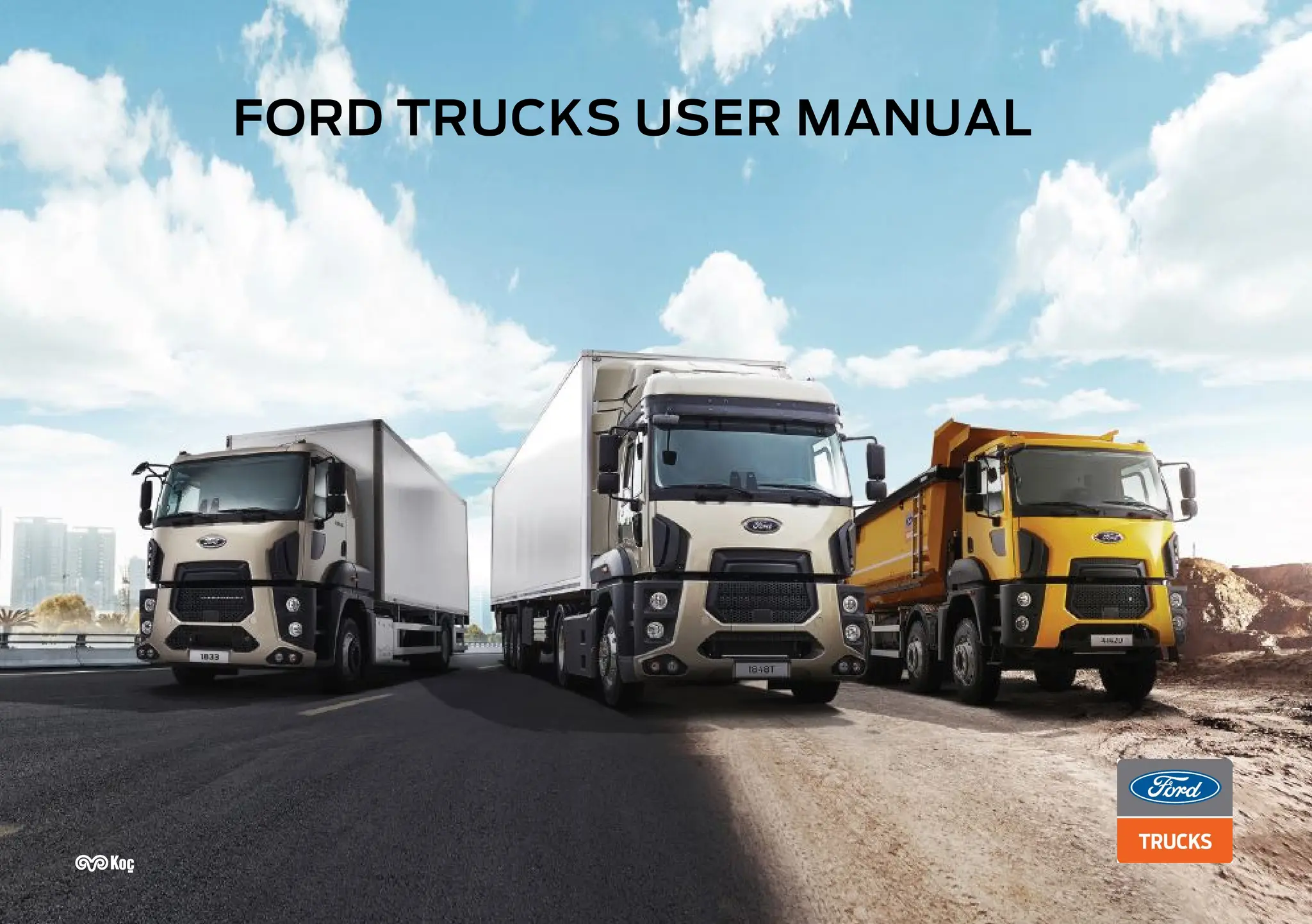
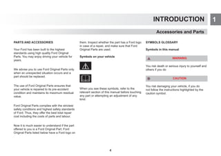
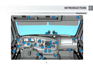
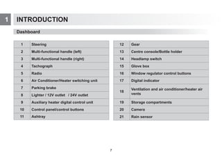
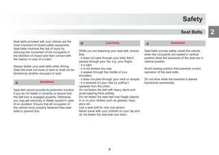
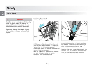
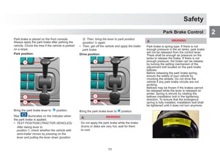
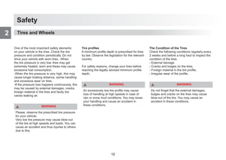
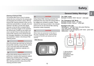
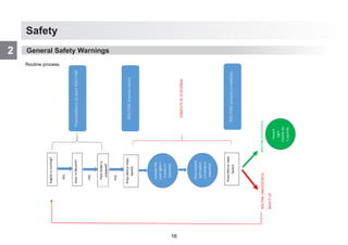
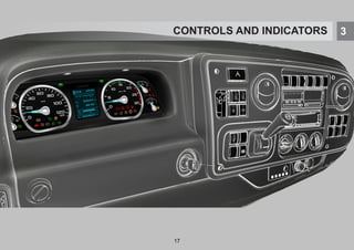
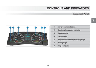
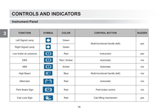
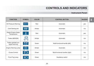
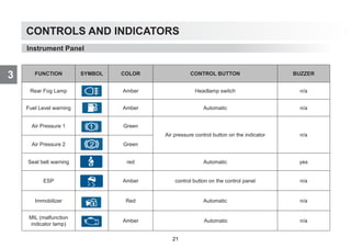
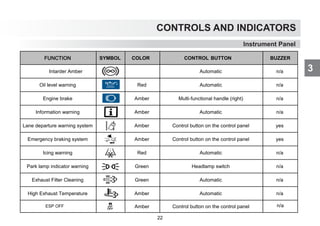
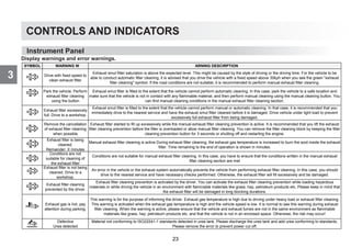
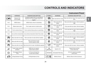
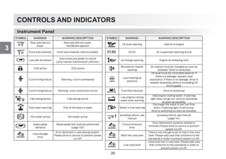
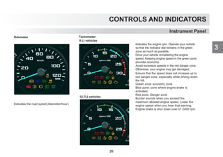
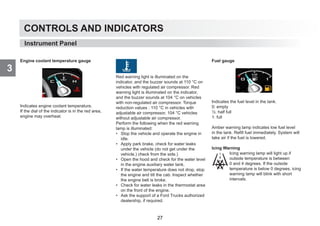
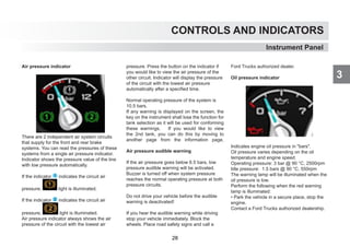
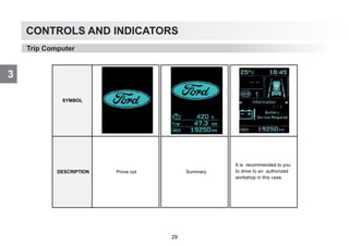
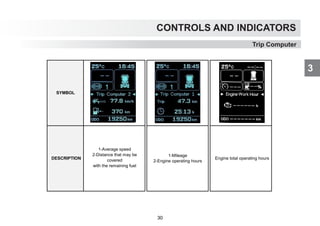
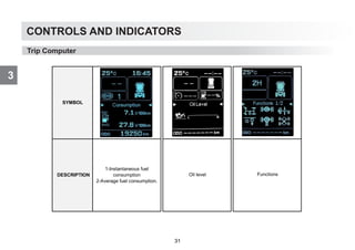
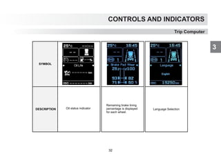
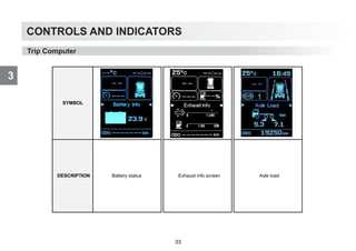
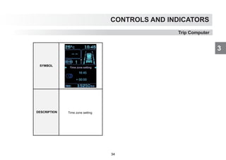
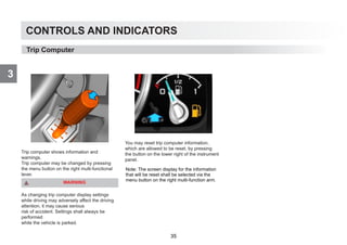
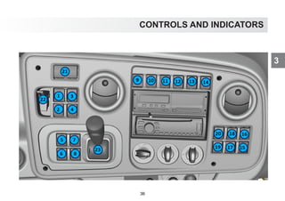
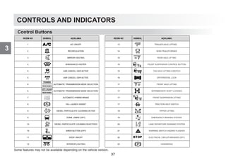
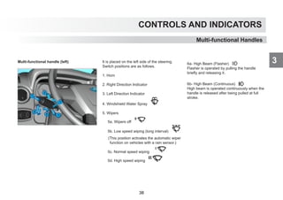
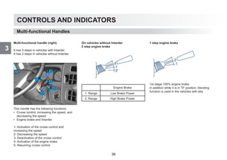
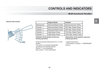
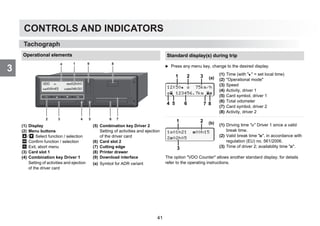
![CONTROLS AND INDICATORS
3
25
1
Introducing Your Vehicle
Indicators
Tachograph
Calling up menu functions
Possible only when the vehicle is stationary!
왘 Use the buttons / to select the desired display.
왘 Use button to call up the main menu.
왘 Use / to select the listed functions step by step.
Print daily value:
왘 [printout driver 1] ... [24h day] ... [25.10.2017] ...
[printout in UTC yes/no]
Enter Out of scope beginning / end:
왘 [entry vehicle] ... [OUT begin] or [OUT end]
Enter Beginning of ferry / train:
왘 [entry vehicle] ... [ ferry/train]
왘 Set the current activity.
Set Local time:
왘 [entry vehicle] ... [ local time] ...
왘 Set Local time in steps of ± 30 minutes.
103h46 00h15
125h57 00h21
12:40 0km/h
123456.7km
201h10 00h36
215h00 00h21
select
language?
call main menu?
UTC 29.09.2017
10:40 +02h00
printout
driver 1
language
english
1. Main menu
... others see operating
instructions
VDOi 9h 2
∆|19h58 10h 1
VDO 00h44
11h00 03h23
Option: VDO Counter, for
details see operating
instructions.
42](https://image.slidesharecdn.com/fordtrucksusermanuel-260131172527-60bc944e/85/fordtrucksusermanuel-pdf-bbbbbbbbbbbbbb-44-320.jpg)
![CONTROLS AND INDICATORS
3
46
CONTROLS AND INDICATORS
3
Tachograph
Tachograph
Insert paper roll
왘 Press the unlocking surface on the printer panel, the printer drawer
opens.
왘 Pull the printer drawer out of the DTCO.
왘 Insert new paper roll according to the illustration and guide it via the
pulley (1).
왘 Push printer drawer into the printer compartment until it engages.
왘 The printer is ready for operation.
You can start a printout.
Make sure that the paper roll does not become jammed in the
printer drawer and the start of the paper (1) extends beyond the
edge of the printer drawer!
1 2
Messages
(1) Pictogram and plain text of the message
! = Event, example [! driving without card]
x = Fault, example [x sensor fault]
= Driving time warning [1 break!]
Operational note, example [o no paper]
(2) Error code
For further messages and measures refer to the operating instructions.
Acknowledge message:
왘 Press key 2 times, the message disappears.
x1 internal
fault xx
1
2
Times of the driver card(s)
.
(1) Driving time since a valid break
time.
(2) Valid break time , in accordance
with regulation (EU) no. 561/2006.
(3) Driving time over two weeks .
(4) Duration of the set activity.
103h46 00h15
125h57 00h21
1 2
3 4
43](https://image.slidesharecdn.com/fordtrucksusermanuel-260131172527-60bc944e/85/fordtrucksusermanuel-pdf-bbbbbbbbbbbbbb-45-320.jpg)
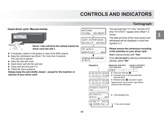
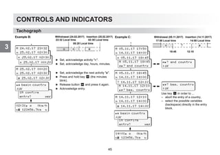
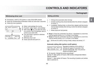
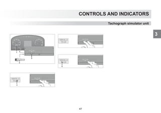
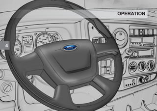
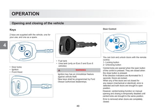
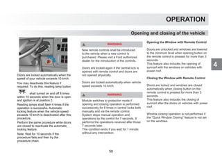
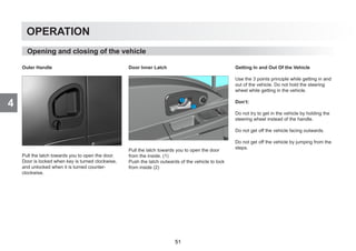
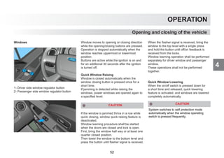
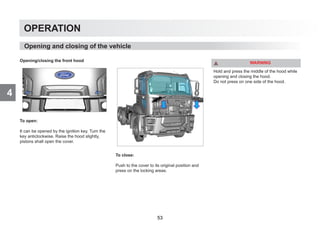
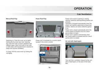
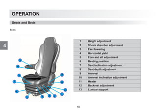
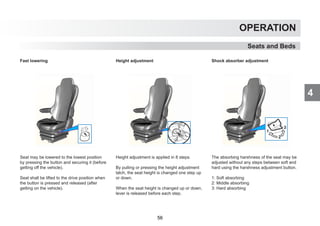
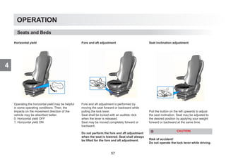
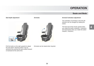
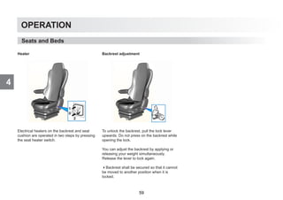
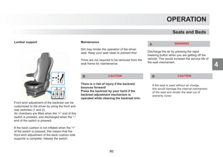
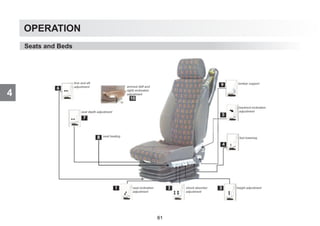
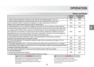
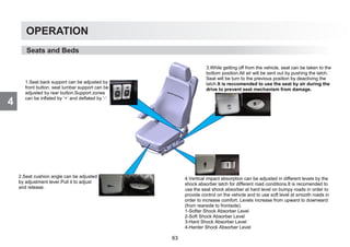
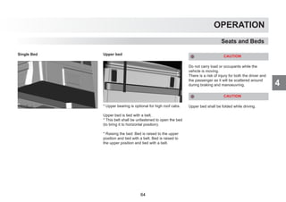

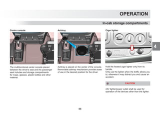
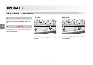
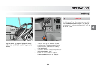
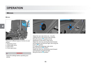
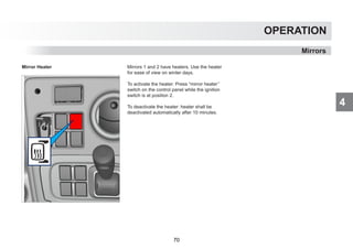
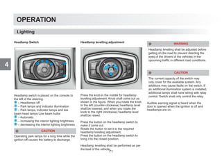
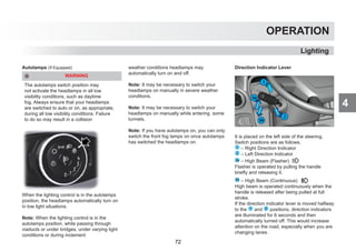
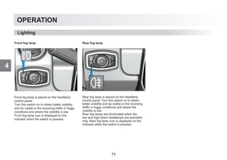
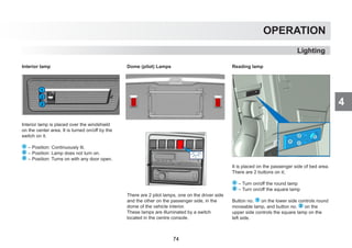

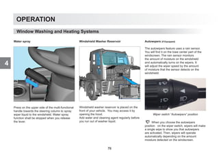
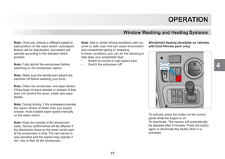
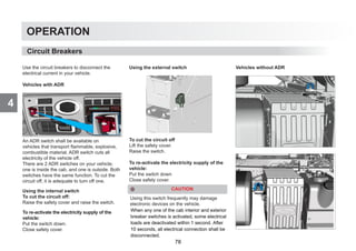

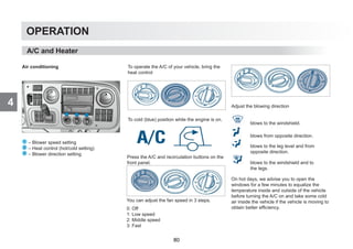
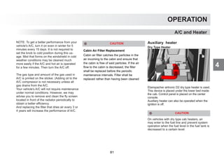
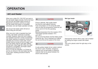
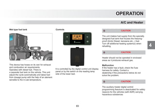
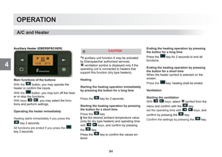
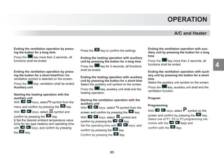
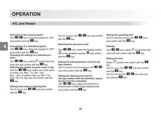
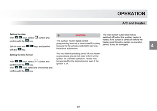
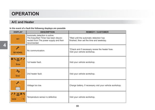
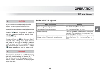
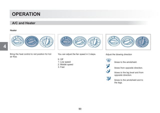
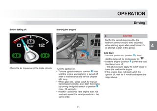
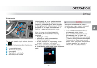
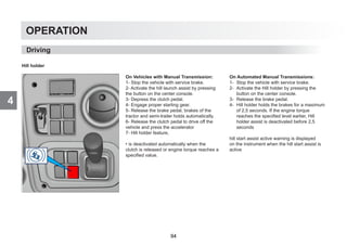
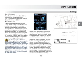
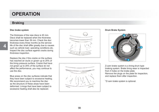
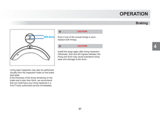
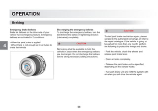
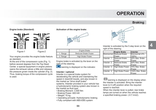
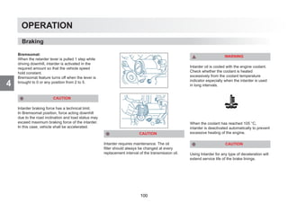
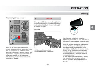
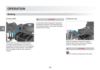
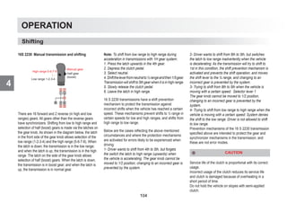
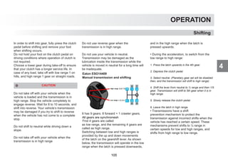
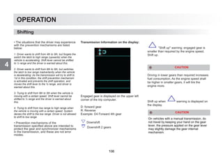
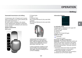
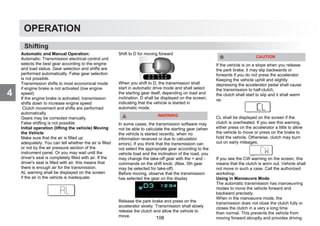
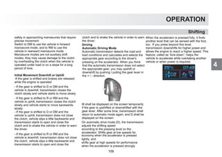
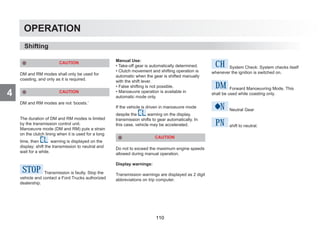
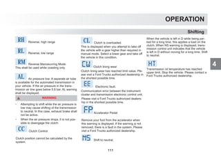
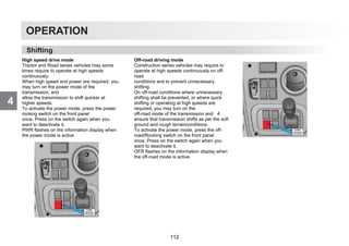
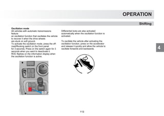
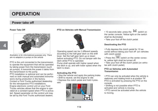
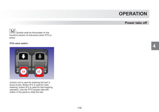
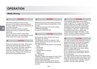
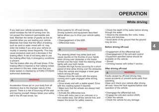
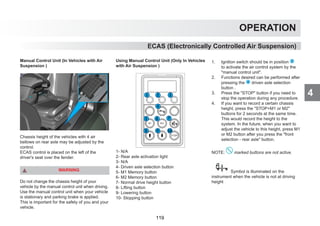
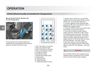
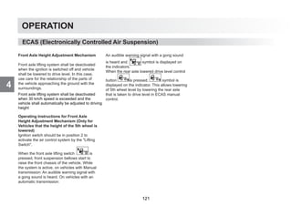
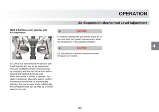
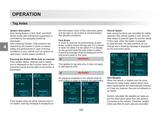
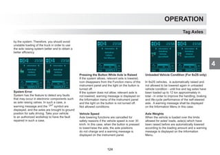
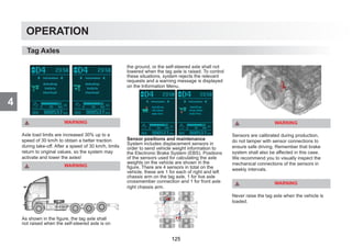
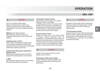
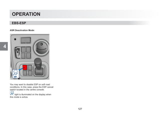
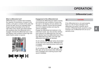
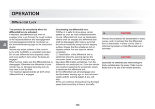
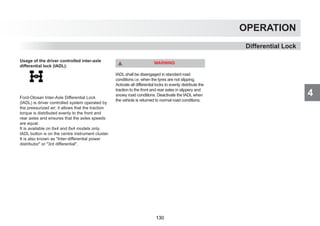
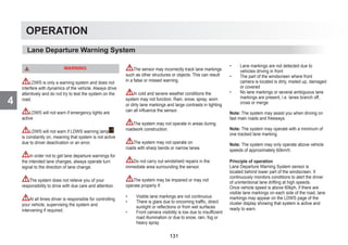
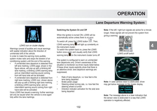
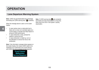
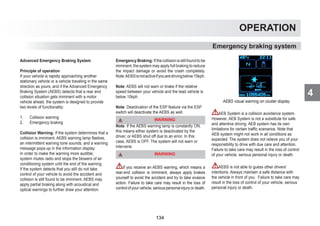
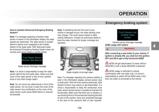
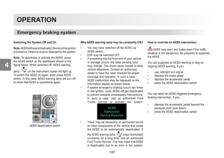
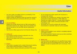
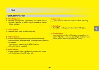
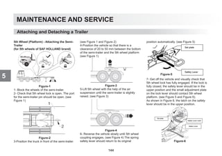
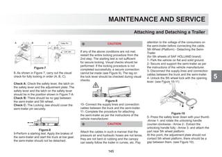
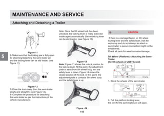
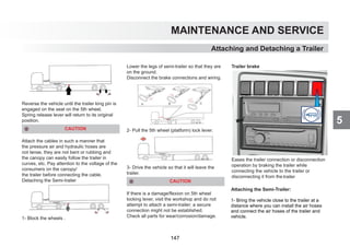
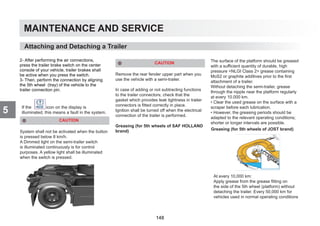
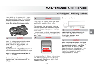
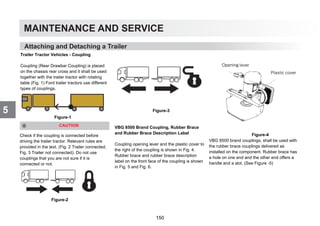
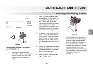
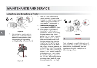
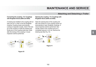
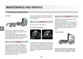
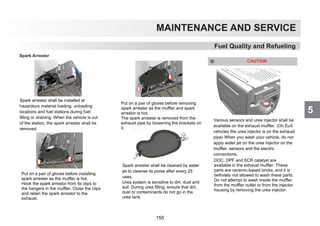
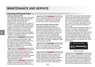
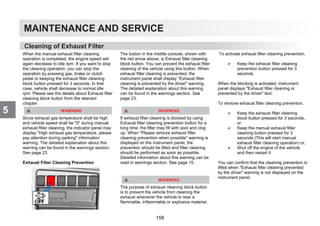
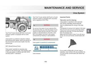
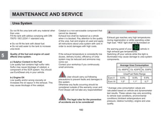
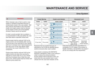
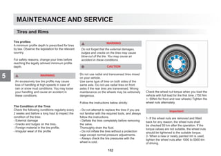
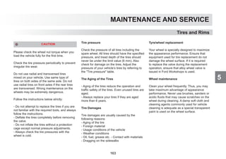
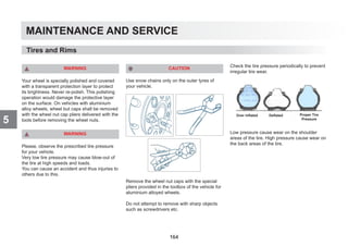
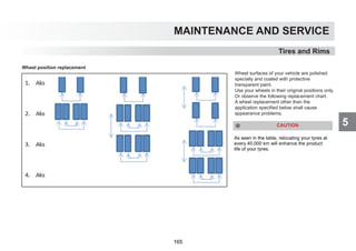
![MAINTENANCE AND SERVICE
5
- Contact your dealership to select the correct size when you replace the tire.
- Always check the tire pressures with the wheel is cold.
Tires and Rims
Tire Size Rim Load Index Tire 6,0 6,25 6,5 6,75 7,0 7,25 7,5 7,75 8,0 8,25 8,5 8,6 8,75 9,00
Single ‐ ‐ ‐ ‐ ‐ ‐ ‐ ‐ ‐ ‐ ‐ ‐ ‐ ‐
Double ‐ ‐ 9000 ‐ 10000 ‐ 10500 ‐ 11000 ‐ 11600 ‐ 12000 12300
154/148 Single 5420 5600 5780 5955 6130 6305 6480 6650 6825 6990 7160 ‐ 7330 7500
152/148 Double ‐ ‐ ‐ 10000 10300 10600 10800 ‐ ‐ 11600 12000 ‐ 12300 12600
Single 5420 5600 5780 5955 6130 6305 6480 6650 6825 6990 7160 ‐ 7330 7500
Double 9685 10005 10325 10640 10955 11270 11580 11890 12195 12450 12800 ‐ ‐ ‐
Single ‐ ‐ ‐ ‐ 6000 6200 6400 ‐ 6700 6900 7100 ‐ ‐ ‐
Double ‐ ‐ 10000 ‐ 10700 11000 11400 11700 12000 12300 12600 ‐ ‐ ‐
Single ‐ 6200 6400 6600 6800 7000 7200 7400 7600 7800 8000 ‐ ‐ ‐
Double ‐ 10400 10800 11100 11400 11800 12000 12400 12700 13000 13400 ‐ ‐ ‐
Single ‐ ‐ 5560 ‐ 5950 ‐ 6330 ‐ 6720 ‐ 7100 ‐ ‐ ‐
Double ‐ ‐ 9880 ‐ 10560 ‐ 11240 ‐ 11920 ‐ 12600 ‐ ‐ ‐
Single 6360 6540 6730 6910 7100 7280 7460 7640 7820 8000 ‐
Double 10650 10960 11270 11580 11890 12200 12500 12800 13100 13400 ‐
Single 6750 6970 7190 7410 7630 7850 8070 8280 8490 8710 8920 9000 ‐ ‐
Double 12000 12390 12790 13180 13500 13960 14340 14720 15100 15480 15850 16000 ‐ ‐
13R22,5 9,00x22,5 156/150
12.00 R24 8,50x24 160/156
315/80 R22,5 9.00X22.5 156/150
12R 22,5 9.00X22.5 152/148
315/70R22,5 9,00x22,5 154/150
295/80 R22,5 9.00X22.5 152/148
TIRE PRESSURE [Bar]
295/60 R22,5 9.00X22.5 150/147
315/60 R22,5 9.00X22.5
166](https://image.slidesharecdn.com/fordtrucksusermanuel-260131172527-60bc944e/85/fordtrucksusermanuel-pdf-bbbbbbbbbbbbbb-168-320.jpg)