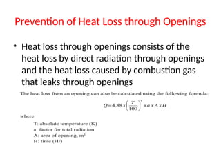
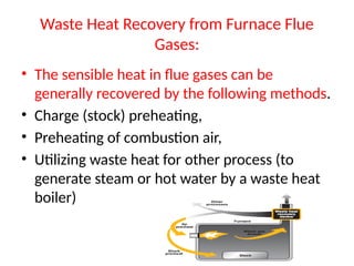
Energy Saving
Thermal Utility
FUELS AND COMBUSTION
Introduction to Fuels
• The various types of fuels like liquid, solid and gaseous
fuels are available for firing in boilers, furnaces and other
combustion equipments. The selection of right type of
fuel depends on various factors such as availability,
storage, handling, pollution and landed cost of fuel
• The knowledge of the fuel properties helps in selecting
the right fuel for the right purpose and efficient use of the
fuel. The following characteristics, determined by
laboratory tests, are generally used for assessing the
nature and quality of fuels.
Properties of Liquid Fuels
• Density
• This is defined as the ratio of the mass of the fuel to the volume of
the fuel at a reference temperature of 15°C. Density is measured
by an instrument called hydrometer. The knowledge of density is
useful for quantity calculations and assessing ignition quality.
• Specific gravity
• This is defined as the ratio of the weight of a given volume of oil
to the weight of the same volume of water at a given
temperature.
• Specific gravity is used in calculations involving weights and
volumes.
Properties of Liquid Fuels
• Viscosity
• The viscosity of a fluid is a measure of its internal resistance
to flow
• Viscosity depends on temperature and decreases as the
temperature increases.
• Viscosity is the most important characteristic in the storage
and use of fuel oil.
• It influences the degree of pre-heat required for handling,
storage and satisfactory atomization.
• If the oil is too viscous, it may become difficult to pump,
hard to light the burner, and tough to operate
Properties of Liquid Fuels
• Flash Point
• The flash point of a fuel is the lowest temperature at
which the fuel can be heated so that the vapor gives
off flashes momentarily when an open flame is passed
over it. Flash point for furnace oil is 66 C.
• Specific Heat
• Specific heat is the amount of kcal needed to raise the
temperature of 1 kg of oil by 1 C. The unit of specific
heat is kcal/kg C.
Properties of Liquid Fuels
• Calorific Value
• The calorific value is the measurement of heat or energy
produced, and is measured either as gross calorific value or
net calorific value.
• The difference being the latent heat of condensation of the
water vapor produced during the combustion process.
• Gross calorific value (GCV) assumes all vapor produced during
the combustion process is fully condensed.
• Net calorific value (NCV) assumes the water leaves with the
combustion products without fully being condensed.
• Fuels should be compared based on the net calorific value.
Properties of Liquid Fuels
• GCV = NCV + 584 ((9H2% + M%)/100)
• Where,
• GCV= Gross calorific value of fuel, kcal/kg
• NCV = Net calorific value of fuel, kcal/kg
• H,%= Hydrogen % by weight present in the fuel
• M% = Moisture % by weight present in the fuel
• 584 = Latent heat corresponding to partial
pressure of water vapor, kcal/kg
Properties of Liquid Fuels
• Sulphur
• The amount of sulphur in the fuel oil depends mainly
on the source of the crude oil and to a lesser extent
on the refining process. The normal sulfur content
for the residual fuel oil (furnace oil) is in the order of
2-4 %.
• The main disadvantage of sulphur is the risk of
corrosion by sulphuric acid formed during and
after combustion, and condensing in cool parts of
the chimney or stack, air pre heater and economiser.
Properties of Liquid Fuels
• Ash Content
• The ash value is related to the inorganic material in the fuel oil.
The ash levels of distillate fuels are negligible. Residual fuels
have more of the ash-forming constituents. These salts may be
compounds of sodium, vanadium, calcium, magnesium, silicon,
iron, aluminum, nickel, etc.
• Typically, the ash value is in the range 0.03-0.07 %. Excessive ash
in liquid fuels can cause fouling deposits in the combustion
equipment.
• Ash has erosive effect on the burner tips, causes damage to the
refractory's at high temperatures and gives rise to high
temperature corrosion and fouling of equipments
Properties of Liquid Fuels
• Water Content
• Water content of furnace oil when supplied is normally
very low as the product at refinery site is handled hot
and maximum limit of 1% is specified in the standard.
• Water may be present in free or emulsified form and can
cause damage to the inside furnace surfaces during
combustion especially if it contains dissolved salts. It can
also cause spluttering of the flame at the burner tip,
possibly extinguishing the flame and reducing the flame
temperature or lengthening the flame.
Properties of Liquid Fuels
• Storage of Fuel oil
• It can be potentially hazardous to store furnace oil in barrels. A
better practice is to store it in cylindrical tanks, either above or
below the ground. Furnace oil, that is delivered, may contain
dust, water and other contaminants.
• The sizing of storage tank facility is very important. A
recommended storage estimate is to provide for at least 10
days of normal consumption. Industrial heating fuel storage
tanks are generally vertical mild steel tanks mounted above
ground. It is prudent for safety and environmental reasons to
build bund walls around tanks to contain accidental spillages.
Properties of Liquid Fuels
• Pumping
• Heavy fuel oils are best pumped using positive displacement
pumps, as they are able to get fuel moving when it is cold.
A circulation gear pump running on LDO should give
between 7000-10000 hours of service. Diaphragm pumps
have a shorter service life, but are easier and less expensive
to repair. A centrifugal pump is not recommended, because
as the oil viscosity increases, the efficiency of the pump drops
sharply and the horsepower required increases. Light fuels
are best pumped with centrifugal or turbine pumps. When
higher pressures are required, piston or diaphragm pumps
should be used.
Properties of Liquid Fuels
• Fuel Storage and Pumping Temperature
• The viscosity of furnace oil and LSHS increases with
decrease in temperature, which makes it difficult to pump
the oil. At low ambient temperatures (below 25 °C), furnace
oil is not easily pump able. To circumvent this, preheating
of oil is accomplished in two ways: a) the entire tank may
be preheated. In this form of bulk heating, steam coils are
placed at the bottom of the tank, which is fully insulated;
b) the oil can be heated as it flows out with an outflow
heater. To reduce steam requirements, it is advisable to
insulate tanks where bulk heating is used.
Properties of Liquid Fuels
• Temperature Control
• Thermostatic temperature control of the oil is necessary to
prevent overheating, especially when oil flow is reduced
or stopped. This is particularly important for electric
heaters, since oil may get carbonized when there is no flow
and the heater is on. Thermostats should be provided at a
region where the oil flows freely into the suction pipe. The
temperature at which oil can readily be pumped depends
on the grade of oil being handled. Oil should never be
stored at a temperature above that necessary for pumping
as this leads to higher energy consumption.
Properties of Gaseous Fuels
• Gaseous fuels in common use are liquefied petroleum gases
(LPG), Natural gas, producer gas, blast furnace gas, coke oven
gas etc. The calorific value of gaseous fuel is expressed in kilo
Calories per normal cubic meter (kcal/Nm3) i.e. at normal
temperature (20 °C) and pressure (760 mm Hg)
• Calorific Value
• Since most gas combustion appliances cannot utilize the heat
content of the water vapor, gross calorific value is of little
interest. Fuel should be compared based on the net calorific
value. This is especially true for natural gas, since increased
hydrogen content results in high water formation during
combustion.
Properties of Gaseous Fuels
• LPG
• LPG is a predominant mixture of propane and Butane with a small
percentage of unsaturated (Propylene and Butylene) and some lighter
C2 as well as heavier C5 fractions. Included in the LPG range are
propane (C3Hg), Propylene (C3H6), normal and iso-butane (C H ) and
Butylene (C4Hg).
• They are stored and transported as liquids under pressure for
convenience and ease of handling.
• Liquid LPG evaporates to produce about 250 times volume of gas
• LPG vapor is denser than air
• There should be adequate ground level ventilation where LPG is
stored. For this very reason LPG cylinders should not be stored in cellars
or basements, which have no ventilation at ground level.
Properties of Gaseous Fuels
• Natural Gas
• Methane is the main constituent of Natural gas and accounting
for about 95% of the total volume. Other components are:
Ethane, Propane, Butane, Pentane, Nitrogen, Carbon Dioxide,
and traces of other gases.
• Natural gas is a high calorific value fuel requiring no storage
facilities. It mixes with air readily and does not produce smoke or
soot. It has no sulphur content. It is lighter than air and
disperses into air easily in case of leak
Combustion
• Combustion refers to the rapid oxidation of
fuel accompanied by the production of heat,
or heat and light. Complete combustion of a
fuel is possible only in the presence of an
adequate supply of oxygen.
• Oxygen (O2) is one of the most common
elements on earth making up 20.9% of our air.
Rapid fuel oxidation results in large amounts of
heat.
Combustion
• T’s of Combustion
• The objective of good combustion is to release all
of the heat in the fuel. This is accomplished by
controlling the “three T’s” of combustion which are
• (1) Temperature high enough to ignite and
maintain ignition of the fuel,
• (2) Turbulence or intimate mixing of the fuel and
oxygen, and
• (3) Time sufficient for complete combustion.
Combustion
Too much, or too little fuel with the available combustion air may potentially
result in un-bumed fuel and carbon monoxide generation. A very specific
amount of O2 is needed for perfect combustion and some additional
(excess) air is required for ensuring complete combustion. However, too
much excess air will result in heat and efficiency losses.
Combustion of Oil
• Heating Oil to Correct Viscosity
• When atomizing oil, it is necessary to heat it enough to get the
desired viscosity. This temperature varies slightly for each grade of oil.
The lighter oils do not usually require pre-heating.
• Stoichiometric ‫متكافئ‬ Combustion
• The efficiency of a boiler or furnace depends on efficiency of the
combustion system. The amount of air required for complete combustion of
the fuel depends on the elemental constituents of the fuel that is Carbon,
Hydrogen, and Sulphur etc. This amount of air is called stoichiometric air.
For ideal combustion process for burning one kg of a typical fuel oil
containing 86% Carbon, 12% Hydrogen, 2% Sulphur, theoretically required
quantity of air is 14.1 kg. This is the minimum air that would be required if
mixing of fuel and air by the burner and combustion is perfect.
Combustion of Oil
• Control of Air and Analysis of Flue Gas
• Thus in actual practice, the amount of
combustion air required will be much higher
than optimally needed. Therefore some of the
air gets heated in the furnace boiler and leaves
through the stack without participating in the
combustion
Combustion of Oil
Chemical analysis of the gases is an objective method that helps in
achieving finer air control. By measuring carbon dioxide (CO2) or oxygen
(O2) in flue gases
Combustion of Oil
• Oil Firing Burners
• The burner is the principal device for the firing of fuel. The
primary function of burner is to atomize fuel to millions of
small droplets so that the surface area of the fuel is increased
enabling intimate contact with oxygen in air. The finer the
fuel droplets are atomized, more readily will the particles
come in contact with the oxygen in the air and bum.
• Normally, atomization is carried out by primary air and
completion of combustion is ensured by secondary air.
Burners for fuel oil can be classified on the basis of the
technique to prepare the fuel for burning i.e. atomization.
Combustion of Oil
• Since the velocity of air affects the turbulence, it becomes harder
and harder to get good fuel and air mixing at higher turndown ratios
since the air amount is reduced. Towards the highest turndown
ratios of any burner, it becomes necessary to increase the excess air
amounts to obtain enough turbulence to get proper mixing.
• The better burner design will be one that is able to properly mix the
air and fuel at the lowest possible air flow or excess air.
• An important aspect to be considered in selection of burner is
turndown ratio.
• Turndown ratio is the relationship between the maximum and
minimum fuel input without affecting the excess air level.
• For example, a burner whose maximum input is 250,000 kcal and
minimum rate is 50,000 kcal, has a ‘Turn-Down Ratio’ of 5 to 1.
Combustion of Gas
• Combustion Characteristics of Natural Gas
• The stoichiometric ratio for natural gas (and most gaseous fuels)
is normally indicated by volume. The air to natural gas
(stoichiometric) ratio by volume for complete combustion vary
between 9.5:1 to 10:1
• Natural gas is essentially pure methane, CH4. Its combustion can
be represented as follows:
• CH4+2O2 = CO2 + 2H2O
• So for every 16 kgs of methane that are consumed, 44 kgs of
carbon dioxide are produced. (Remember that the atomic weights
of carbon, oxygen and hydrogen are 12, 16 and 1, respectively.)
Combustion of Gas
Combustion of Gas
• Low-And High-Pressure Gas Burners.
• The important thing in all gas-burning devices is a correct air-and-gas mixture
at the burner tip. Low-pressure burners (Figure 1.7), using gas at a pressure less
than 0.15 kg/cm2 (2 psi)
• In a high-pressure gas mixer the energy of the gas jet draws air into the mixing
chamber and delivers a correctly proportioned mixture to the burner. When the
regulating valve is opened, gas flows through a small nozzle into a venturi tube
(a tube with a contracted section). Entrainment of air with high-velocity gas in
the narrow venturi section draws air in through large openings in the end. The
gas-air mixture is piped to a burner. The gas-burner tip may be in a variety of
forms. In a sealed-in tip type, the proper gas-air mixture is piped to the
burner,
• end is increased or decreased by turning a revolving shutter, which can be
locked in any desired position. Excess air levels in natural gas burner are in the
order of 5%.
Combustion Controls
• Combustion controls assist the burner in regulation
of fuel supply, air supply, (fuel to air ratio), and
removal of gases of combustion to achieve
optimum boiler efficiency.
• The amount of fuel supplied to the burner must be
in proportion to the air pressure and the quantity
of air required.
• The combustion controls are also necessary as
safety device to ensure that the boiler operates
safely.
Combustion Controls
• ON/OFF Control
• The simplest control, ON/OFF control means that either
the burner is firing at full rate or it is OFF. This type of
control is limited to small boilers.
• High/Low/OFF Control
• Slightly more complex is HIGH/LOW/OFF system where the
burner has two firing rates. The burner operates at slower
firing rate and then switches to full firing as needed.
Burner can also revert to low firing position at reduced
load. This control is fitted to medium sized boilers.
Combustion Controls
• Modulating Control
• The modulating control operates on the principle of
matching the steam pressure demand by altering
the firing rate over the entire operating range of the
boiler. Modulating motors use conventional
mechanical linkage or electric valves to regulate the
primary air, secondary air, and fuel supplied to the
burner. Full modulation means that boiler keeps
firing, and fuel and air are carefully matched over the
whole firing range to maximize thermal efficiency.
FURNACES
• A furnace is an equipment to melt metals
for casting or heat materials for change of
shape (Rolling, forging etc) or change of
properties (heat treatment).
Types and Classification of Different Furnaces
• Based on the method of generating heat, furnaces are broadly
classified into two types namely combustion type (using fuels) and
electric type. The combustion type furnace can be broadly classified as
oil fired, coal fired or gas fired, depending upon the kind of combustion.
• Based on the mode of charging of material furnaces can be classified as
(i) Intermittent or Batch type furnace or Periodical furnace and (ii)
Continuous furnace
• Based on mode of waste heat recovery as recuperative and regenerative
furnaces.
• Another type of furnace classification is made based on mode of heat
transfer, mode of charging and mode of heat recovery
• The electric furnaces can be broadly classified as resistance type for
heating and induction and arc for melting of metals.
Types and Classification of Different Furnaces
Characteristics of an Efficient Furnace
• Furnace should be designed so that in a given time, as much of
material as possible can be heated to a uniform temperature as
possible with the least possible fuel.
• To achieve this end, the following parameters can be considered
• Determination of the quantity of heat to be imparted to the material or
charge.
• Liberation of sufficient heat within the furnace to heat the stock and
overcome all heat losses.
• Transfer of available part of that heat from the furnace gases to the
surface of the heating stock.
• Equalization of the temperature within the stock.
• Reduction of heat losses from the furnace to the minimum possible
extent
Furnace Energy Supply
• Since the products of flue gases directly contact the stock, type of fuel chosen
is of importance. For example, some materials will not tolerate sulphur ‫كبريت‬
in the fuel.
• Also use of solid fuels will generate particulate matter, which will interfere
with the stock place inside the furnace. Hence, vast majority of the furnaces
use liquid fuel, gaseous fuel or electricity as energy input.
• Electricity is used in induction and arc furnaces for melting steel and cast
iron. Non-ferrous melting utilizes oil as fuel.
• furnace heating the stock to 1200 °C will have its exhaust gases leaving at
least at 1200 °C resulting in a huge heat loss through the stack. However,
improvements in efficiencies have been brought about by methods such as
preheating of stock, preheating of combustion air and other waste heat
recovery systems.
Typical Furnace System
• Forging Furnaces
• The forging furnace is used for preheating billets and
blooms to attain a ‘forge’ temperature. The furnace
temperature is maintained at around 1200 to 1250 °C.
Forging furnaces use an open fireplace system and most of
the heat is transmitted by radiation.
• The total operating cycle can be divided into (a) heat up time
(b) soaking time and (c) forging time.
• Normally, large pieces are soaked for 4 to 6 hrs inside the
furnace to attain uniform temperature throughout the
cross-section of the material
Typical Furnace System
• Rerolling Mill Furnace
• Batch type
• A box type furnace is employed for batch type rerolling mill.
The furnace is basically used for heating up scrap, small ingots
and billets weighing 2 to 20 kg for rerolling
• The operating temperature is about 1200 °C.
• The total cycle time can be further categorized into heat-up
time and rerolling time. During heat-up time the material gets
heated up to the required temperature and is removed
manually for rerolling. The average output from these
furnaces varies from 10 to 15 tonnes / day.
Typical Furnace System
• Rerolling Mill Furnace
• Continuous Pusher Type
• The process flow and operating cycles of a continuous
pusher type is the same as that of the batch furnace. The
operating temperature is about 1250 °C. Generally, these
furnaces operate 8 to 10 hours with an output of 50 to 100
tonnes per day
• The material or stock recovers a part of the heat in flue
gases as it moves down the length of the furnace
Typical Furnace System
• Rerolling Mill Furnace
• Continuous Steel Reheating Furnaces
• The main function of a reheating furnace is to raise the
temperature of a piece of steel, typically to between 900 °C
and 1250 °C, until it is plastic enough to be pressed or rolled
to the desired section, size or shape, The furnace must also
meet specific requirements and objectives in terms of stock
heating rates for metallurgical and productivity reasons.
• In continuous reheating, the steel stock forms a continuous
flow of material and is heated to the desired temperature as it
travels through the furnace.
Rerolling Mill Furnace
• Furnace Feature
• A refractory chamber constructed of insulating materials for retaining heat at
the high operating temperatures.
• A hearth to support or carry the steel. This can consist of refractory materials or
an arrangement of metallic supports that may be water-cooled.
• Burners that use liquid or gaseous fuels to raise and maintain the temperature
in the chamber.
• Coal or electricity can be used for reheating.
• A method of removing the combustion exhaust gases from the chamber
• A method of introducing and removing the steel from the chamber.
• These facilities depend on the size and type of furnace, the shape and
size of the steel being processed, and the general layout of the rolling mill.
• Common systems include roller tables, conveyors, charging machines and
furnace pushers
Induction Furnaces
• Induction furnaces are ideal for melting
and alloying a wide variety of metals with
minimum melt losses, however, little refining
of the metal is possible. There are two main
types of induction furnace: coreless and
channel
Induction Furnaces
• Coreless Induction Furnace
• consists of: a water cooled coil made of a copper
tube, a crucible ‫بوتقه‬ installed within the coil
and supporting shell equipped with trunnions
‫الدوران‬ ‫مرتكز‬on which the furnace may tilt.
• Alternating current passing through the coil
induces alternating currents in the metal charge
loaded to the crucible. These induced currents
heat the charge
Induction Furnaces
Induction Furnaces
Induction Furnaces
• Example - Melting of M.S. scrap
• Calculate the furnace efficiency from the data given below
• Specific heat - 0.682 kJ/kg °C
• Latent heat - 272 kJ/kg
• Melting temperature - 1650 °C
• Charge temperature -30 °C
• Quantity of metal - 1000 kg
• Quantity of slag -25 kg
• Electricity consumed - 625 kWh
Induction Furnaces
Induction Furnaces
• Distribution of losses in induction furnace
• Losses in induction furnace
• The theoretical energy require to melt one Ton of steel is 385 TO 400
kWh/Ton.
• However in actual practice,
• the specific energy consumption is remarkably higher to 550 - 950
kWh/ton.
• Power loss in generator / panel 2 - 4 %
• Power loss in capacitor Bank 1.0 - 3 %
• Power loss in Crucible (Water cooled cables, Bus bar, and change
over switches) 18-25%
• Radiation loss 7 - 9%
Induction Furnaces
• Factors affecting the furnace efficiency
• Due to poor maintenance the total production stops sometimes. Higher
breakdown results in increasing the’ cost of production
• Due to low supply voltage the furnace draws less power, causes slow melting
and inefficient operation resulting increase in production cost.
• Some time lining material selection is wrong with respect to metal. Basic
lining is better conductor of heat compared to acidic lining. Wrong lining
selection increases breakdown, Furnace down time and furnace losses,
resulting in inefficient operation.
• Poor coordination between melting staff & contractor
• Absence of material handling equipment
• Poor molding efficiency, so furnace on hold
• Poor quality scrap, reducing lining life, takes more time to melt.
• Absence of thermal insulation between lining & coil.
Performance Evaluation of a Typical Fuel
Fired Furnace
• Thermal efficiency of process heating equipment, such as
furnaces, ovens, heaters, and kilns is the ratio of heat
delivered to a material and heat supplied to the heating
equipment
• The reasons for low furnace efficiency include?
• High stack temperature and excess air levels.
• Low capacity utilization/ hearth loading.
• Radiation losses due to opening.
• Surface heat losses.
• Batch operation involving heating, cooling and soaking cycles.
Performance Evaluation of a Typical Fuel
Fired Furnace
• Heat losses in industrial heating Furnaces
• Stored heat loss: First, the metal structure and
insulation of the furnace must be heated so their
interior surfaces are about the same temperature as the
product they contain. This stored heat is held in the
structure until the furnace shuts down, then it leaks
out into the surrounding area. The more frequently the
furnace is cycled from cold to hot and back to cold
again, the more frequently this stored heat must be
replaced. Fuel is consumed with no useful output.
Performance Evaluation of a Typical Fuel
Fired Furnace
• Heat losses in industrial heating Furnaces
• Wall losses: Additional heat losses take place while the
furnace is in production. Wall or transmission losses are
caused by the conduction of heat through the walls, roof,
and floor of the heating device
• Material handling losses: Many furnaces use equipment
to convey the work into and out of the heating chamber,
and this can also lead to heat losses. Conveyor belts or
product hangers that enter the heating chamber cold and
leave it at higher temperatures drain energy from the
combustion gases.
Performance Evaluation of a Typical Fuel
Fired Furnace
• Heat losses in industrial heating Furnaces
• Cooling media losses. Water or air cooling protects rolls,
bearings, and doors in hot furnace environments, but at the
cost of lost energy
• Radiation (opening) losses. Furnaces and ovens operating at
temperatures above 540°C might have significant radiation losses
• Waste-gas losses. Waste-gas loss, also known as flue gas or
stack loss, is made up of the heat that cannot be removed from
the combustion gases inside the furnace.
• Air infiltration. Excess air does not necessarily enter the furnace
as part of the combustion air supply.
Performance Evaluation of a Typical Fuel
Fired Furnace
Performance Evaluation of a Typical Fuel
Fired Furnace
General Fuel Economy Measures in Furnaces
• Typical energy efficiency measures for an industry with furnace
are:
• 1) Complete combustion with minimum excess air
• 2) Correct heat distribution
• 3) Operating at the desired temperature
• 4) Reducing heat losses from furnace openings
• 5) Maintaining correct amount of furnace draught
• 6) Optimum capacity utilization
• 7) Waste heat recovery from the flue gases
• 8) Minimum refractory losses
• 9) Use of Ceramic Coatings
Complete Combustion with Minimum Excess
Air
Proper Heat Distribution:
• Furnace design should be such that in a given time, as much of the stock
could be heated uniformly to a desired temperature with minimum fuel
firing rate
• The flame should not touch any solid object and should propagate clear of
any solid object.
• Any obstruction will de atomize the fuel particles thus affecting combustion
and create black smoke
• The flames of different burners in the furnace should stay clear of each
other. If they intersect, inefficient combustion would occur
• The burner flame has a tendency to travel freely in the combustion space
just above the material.
• The larger burners produce a long flame, which may be difficult to contain
within the furnace walls. More burners of less capacity give better heat
distribution in the furnace and also increase furnace life.
Maintaining Optimum Operating
Temperature of Furnace
• It is important to operate the furnace at optimum
temperature.
• Operating at too high temperatures than optimum
causes heat loss, excessive oxidation, de­
carbonization as well as over-stressing of the
refractories ‫للصهر‬ ‫المقاومة‬ ‫المواد‬.
• Temperature controls are normally left to operator
judgment, which is not desirable. To avoid
human error, on/off controls should be
provided.
Prevention of Heat Loss through Openings
• Heat loss through openings consists of the
heat loss by direct radiation through openings
and the heat loss caused by combustion gas
that leaks through openings
Optimum Capacity Utilization
• One of the most vital factors affecting
efficiency is loading. There is a particular
loading at which the furnace will operate at
maximum thermal efficiency. If the furnace is
under loaded a smaller fraction of the
available heat in the working chamber will be
taken up by the load and therefore efficiency
will be low
Waste Heat Recovery from Furnace Flue
Gases:
• The sensible heat in flue gases can be
generally recovered by the following methods.
• Charge (stock) preheating,
• Preheating of combustion air,
• Utilizing waste heat for other process (to
generate steam or hot water by a waste heat
boiler)
Minimizing Wall Losses:
• The heat losses from furnace walls affect
the fuel economy considerably. The extent
of wall losses depends on:
• Emissivity of wall
• Thermal conductivity of refractories
• Wall thickness
Use of Ceramic Coatings
• Ceramic coatings in furnace chamber promote rapid
and efficient transfer of heat, uniform heating and
extended life of refractories. The emissivity of
conventional refractories decreases with increase in
temperature whereas for ceramic coatings it
increases. This outstanding property has been
exploited for use in hot face insulation.
• Ceramic coatings are high emissivity coatings which
when applied has a long life at temperatures up to
1350°C
INSULATION AND
REFRACTORIES
Purpose of Insulation
• A thermal insulator is a poor conductor of heat and has
a low thermal conductivity. Insulation is used in
buildings and in manufacturing processes to prevent
heat loss or heat gain
• Thermal insulation delivers the following benefits:
• Reduces over-all energy consumption
• Offers better process control by maintaining process
temperature.
• Provides fire protection to equipment
• Absorbs vibration
Insulation Types and Application
• Low Temperature Insulations (up to 90°C)
• This range covers insulating materials for refrigerators, cold
and hot water systems, storage tanks, etc. The commonly
used materials are Cork‫فلين‬ , Wood, Mineral Fibers,
Polyurethane and expanded Polystyrene, etc
• Medium Temperature Insulations (90 - 325°C)
• Insulators in this range are used in low temperature,
heating and steam raising equipment, steam lines, flue
ducts etc. The types of materials used in this temperatures
range include Asbestos, Calcium Silicate and Mineral Fibers
etc
Insulation Types and Application
• High Temperature Insulations (325° C - above)
• Typical uses of such materials are super
heated steam system, oven dryer and furnaces
etc. The most extensively used materials in
this range are Asbestos, Calcium Silicate,
Mineral Fibre, Mica and Silica based
insulation and Ceramic Fibre.
Insulation material
• Insulation materials can also be classified
into organic and inorganic types.
• Organic insulations are based on
hydrocarbon polymers,
• Inorganic insulation is based on
Siliceous/Aluminous/Calcium materials in
fibrous, granular or powder forms.
Refractories
• Any material can be described as ‘refractory,’ if it
can with stand the action of corrosive solids,
liquids or gases at high temperatures. Examples
are: Alumina, magnesite, chrome magnesite,
dolomite etc. Refractory materials are made in
varying combinations and shapes and for
different requirements of high temperature
processes carried out in metal extraction,
cement, glassmaking, manufacturing, ceramic etc
The general requirements of a refractory
material
• Ability to withstand high temperatures.
• Ability to withstand sudden changes of temperatures.
• Ability to withstand action of molten metal slag, glass,
hot gases, etc.
• Ability to withstand load at service conditions.
• Ability to withstand load and abrasive forces‫جلخ‬ .
• Low coefficient of thermal expansion.
• Should be able to conserve heat.
• Should not contaminate‫تلوث‬ the material with which it
comes into contact
BOILERS
BOILERS
• A boiler is an enclosed vessel that provides a
means for combustion heat to be transferred
into water until it becomes heated water or
steam.
• The process of heating a liquid until it reaches
its gaseous state is called evaporation
BOILERS
• Heat is transferred from one body to another by
means of
• (1) radiation, which is the transfer of heat from a hot
body to a cold body without a conveying medium
‫الكهرومغناطيسية‬ ‫الموجات‬ ‫بواسطة‬ ‫الحرارة‬ ‫انتقال‬
‫حرارتها‬ ‫درجة‬ ‫بسبب‬ ‫األجسام‬ ‫تنتجها‬ ‫التي‬,
• (2) convection, the transfer of heat by a conveying
medium, such as air or water
• (3) conduction, transfer of heat by actual physical
contact, molecule to molecule.
BOILERS
• The boiler system comprises of.
• The feed water system provides water to the boiler and
regulates it automatically to meet the steam demand. Various
valves provide access for maintenance and repair.
• The steam system collects and controls the steam produced in
the boiler. Steam is directed through a piping system to the
point of use. Throughout the system, steam pressure is
regulated using valves and checked with steam pressure
gauges.
• The fuel system includes all equipment used to provide fuel to
generate the necessary heat. The equipment required in the
fuel system depends on the type of fuel used in the system.
BOILERS
BOILERS
• In the figure
• A. Flue gas heat recovery system using economizer
• B. Heat recovery from continuous blow down
• C. Utilization of high pressure steam in the
process
• D. use of low pressure steam (reduced by PRV) in
the process
• E. Condensate The water supplied to the boiler
that is converted into steam is called feed water
BOILERS
• In the figure
• The two sources of feed water are:
• (1) Condensate or condensed steam returned from the
processes and
• (2) Makeup water (treated raw water) which must come
from outside the boiler room and plant processes.
• In high capacity boilers, for higher efficiencies, besides
the economizer for preheating the water an air pre-
heater is also installed to preheat the combustion air.
Boiler Types and Classifications
• Fire tube or “fire in tube” boilers; contain long
steel tubes through which the hot gasses from
a furnace pass and around which the water to
be converted to steam circulates.
• Fire tube boilers, typically have a lower initial
cost, are more fuel efficient and easier to
operate, but they are limited generally to
capacities of 25 tons/hr and pressures of 17.5
kg/cm2
Boiler Types and Classifications
• Water tube or “water in tube” boilers in which
the conditions are reversed with the water
passing through the tubes and the hot gasses
passing outside the tubes
• These boilers can be of single- or multiple-
drum type.
• These boilers can be built to any steam
capacities and pressures, and have higher
efficiencies than fire tube boilers.
Boiler Types and Classifications
• Packaged Boiler: The packaged boiler is so
called because it comes as a complete package.
• Once delivered to site, it requires only the
steam, water pipe work, fuel supply and
electrical connections to be made for it to
become operational.
• Package boilers are generally of shell type with
fire tube design so as to achieve high heat
transfer rates by both radiation and convection
Boiler Types and Classifications
• The features of package boilers are:
• Small combustion space and high heat release
rate resulting in faster evaporation,
• Large number of small diameter tubes leading to
good convective heat transfer,
• Number of passes resulting in better overall heat
transfer.
• Higher thermal efficiency levels compared with
other boilers.
Boiler Types and Classifications
Performance Evaluation of Boilers
• The performance parameters of a boiler like evaporation
ratio and efficiency deteriorate with time due to poor
combustion, heat transfer surface fouling and poor
operation and maintenance.
• Even for a new boiler, reasons such as deteriorating ‫تدهور‬
fuel quality, water quality etc, can result in poor boiler
performance.
• Evaporation ratio trending and Boiler efficiency tests help
to find out the deviation of boiler efficiency from the rated
values and target problem areas for corrective action
Performance Evaluation of Boilers
• Boiler Evaporation Ratio
• Boiler Evaporation ratio, also known as
Steam to fuel ratio, is a common and
simple indicator for boiler performance
trending.
Boiler Efficiency
• Thermal efficiency of a boiler is defined as the percentage
of heat input that is effectively utilized to generate steam.
• a) Direct method: Where the energy gain of the
working fluid (water and steam) is compared with the
energy content of the boiler fuel.
• b) Indirect or Loss method: Where the efficiency is
the difference between the losses and the energy input
• Indirect method is also called as heat loss method. The
efficiency is arrived at, by subtracting the heat loss
fractions from 100.
Direct method& Indirect or Loss method
Boiler Efficiency
• Advantages of direct method:
• Plant people can evaluate the efficiency of boilers quickly
• Requires few parameters for computation
• Needs few instruments for monitoring
• The constraints with the direct efficiency method:
• Accuracy of steam/feed water flow measurement and
fuel measurement are prone to errors
• Steam quality assessment in case of saturated steam
conditions is prone to error as prevalence of wet steam is
common in many boilers
Improving Boiler Availability
• Reducing Boiler Tube Leakage
• Tube failures in boilers lead to reduction in availability and call
for continuous efforts to minimize the tube leakages
• Mechanical causes
• Mechanical damage of tubes takes place due to fly ash erosion,
• Chemical causes
• Water side and fire side corrosion failure of tubes occurs
• Preservation of Boiler
• The internal surfaces of the boiler are prone to corrosion by
leftover water after operation or by atmospheric oxygen when
they are out of service.
Improving Boiler Availability
• Metallurgical causes
• In high temp components like super heaters, re-
heaters creep‫متسلل‬ damage occurs due to
overheating wherein the tube material loses its
strength and failure occurs by stress rupture.
• Quality assurance gaps
• Tube failures are also known to occur due to
inadequate quality assurance procedures during
design/ manufacturing of boiler tubes.

Energy saving in thermal utility.boilers engines

  • 1.
  • 2.
  • 3.
    Introduction to Fuels •The various types of fuels like liquid, solid and gaseous fuels are available for firing in boilers, furnaces and other combustion equipments. The selection of right type of fuel depends on various factors such as availability, storage, handling, pollution and landed cost of fuel • The knowledge of the fuel properties helps in selecting the right fuel for the right purpose and efficient use of the fuel. The following characteristics, determined by laboratory tests, are generally used for assessing the nature and quality of fuels.
  • 4.
    Properties of LiquidFuels • Density • This is defined as the ratio of the mass of the fuel to the volume of the fuel at a reference temperature of 15°C. Density is measured by an instrument called hydrometer. The knowledge of density is useful for quantity calculations and assessing ignition quality. • Specific gravity • This is defined as the ratio of the weight of a given volume of oil to the weight of the same volume of water at a given temperature. • Specific gravity is used in calculations involving weights and volumes.
  • 5.
    Properties of LiquidFuels • Viscosity • The viscosity of a fluid is a measure of its internal resistance to flow • Viscosity depends on temperature and decreases as the temperature increases. • Viscosity is the most important characteristic in the storage and use of fuel oil. • It influences the degree of pre-heat required for handling, storage and satisfactory atomization. • If the oil is too viscous, it may become difficult to pump, hard to light the burner, and tough to operate
  • 6.
    Properties of LiquidFuels • Flash Point • The flash point of a fuel is the lowest temperature at which the fuel can be heated so that the vapor gives off flashes momentarily when an open flame is passed over it. Flash point for furnace oil is 66 C. • Specific Heat • Specific heat is the amount of kcal needed to raise the temperature of 1 kg of oil by 1 C. The unit of specific heat is kcal/kg C.
  • 7.
    Properties of LiquidFuels • Calorific Value • The calorific value is the measurement of heat or energy produced, and is measured either as gross calorific value or net calorific value. • The difference being the latent heat of condensation of the water vapor produced during the combustion process. • Gross calorific value (GCV) assumes all vapor produced during the combustion process is fully condensed. • Net calorific value (NCV) assumes the water leaves with the combustion products without fully being condensed. • Fuels should be compared based on the net calorific value.
  • 8.
    Properties of LiquidFuels • GCV = NCV + 584 ((9H2% + M%)/100) • Where, • GCV= Gross calorific value of fuel, kcal/kg • NCV = Net calorific value of fuel, kcal/kg • H,%= Hydrogen % by weight present in the fuel • M% = Moisture % by weight present in the fuel • 584 = Latent heat corresponding to partial pressure of water vapor, kcal/kg
  • 9.
    Properties of LiquidFuels • Sulphur • The amount of sulphur in the fuel oil depends mainly on the source of the crude oil and to a lesser extent on the refining process. The normal sulfur content for the residual fuel oil (furnace oil) is in the order of 2-4 %. • The main disadvantage of sulphur is the risk of corrosion by sulphuric acid formed during and after combustion, and condensing in cool parts of the chimney or stack, air pre heater and economiser.
  • 10.
    Properties of LiquidFuels • Ash Content • The ash value is related to the inorganic material in the fuel oil. The ash levels of distillate fuels are negligible. Residual fuels have more of the ash-forming constituents. These salts may be compounds of sodium, vanadium, calcium, magnesium, silicon, iron, aluminum, nickel, etc. • Typically, the ash value is in the range 0.03-0.07 %. Excessive ash in liquid fuels can cause fouling deposits in the combustion equipment. • Ash has erosive effect on the burner tips, causes damage to the refractory's at high temperatures and gives rise to high temperature corrosion and fouling of equipments
  • 11.
    Properties of LiquidFuels • Water Content • Water content of furnace oil when supplied is normally very low as the product at refinery site is handled hot and maximum limit of 1% is specified in the standard. • Water may be present in free or emulsified form and can cause damage to the inside furnace surfaces during combustion especially if it contains dissolved salts. It can also cause spluttering of the flame at the burner tip, possibly extinguishing the flame and reducing the flame temperature or lengthening the flame.
  • 12.
    Properties of LiquidFuels • Storage of Fuel oil • It can be potentially hazardous to store furnace oil in barrels. A better practice is to store it in cylindrical tanks, either above or below the ground. Furnace oil, that is delivered, may contain dust, water and other contaminants. • The sizing of storage tank facility is very important. A recommended storage estimate is to provide for at least 10 days of normal consumption. Industrial heating fuel storage tanks are generally vertical mild steel tanks mounted above ground. It is prudent for safety and environmental reasons to build bund walls around tanks to contain accidental spillages.
  • 13.
    Properties of LiquidFuels • Pumping • Heavy fuel oils are best pumped using positive displacement pumps, as they are able to get fuel moving when it is cold. A circulation gear pump running on LDO should give between 7000-10000 hours of service. Diaphragm pumps have a shorter service life, but are easier and less expensive to repair. A centrifugal pump is not recommended, because as the oil viscosity increases, the efficiency of the pump drops sharply and the horsepower required increases. Light fuels are best pumped with centrifugal or turbine pumps. When higher pressures are required, piston or diaphragm pumps should be used.
  • 14.
    Properties of LiquidFuels • Fuel Storage and Pumping Temperature • The viscosity of furnace oil and LSHS increases with decrease in temperature, which makes it difficult to pump the oil. At low ambient temperatures (below 25 °C), furnace oil is not easily pump able. To circumvent this, preheating of oil is accomplished in two ways: a) the entire tank may be preheated. In this form of bulk heating, steam coils are placed at the bottom of the tank, which is fully insulated; b) the oil can be heated as it flows out with an outflow heater. To reduce steam requirements, it is advisable to insulate tanks where bulk heating is used.
  • 15.
    Properties of LiquidFuels • Temperature Control • Thermostatic temperature control of the oil is necessary to prevent overheating, especially when oil flow is reduced or stopped. This is particularly important for electric heaters, since oil may get carbonized when there is no flow and the heater is on. Thermostats should be provided at a region where the oil flows freely into the suction pipe. The temperature at which oil can readily be pumped depends on the grade of oil being handled. Oil should never be stored at a temperature above that necessary for pumping as this leads to higher energy consumption.
  • 16.
    Properties of GaseousFuels • Gaseous fuels in common use are liquefied petroleum gases (LPG), Natural gas, producer gas, blast furnace gas, coke oven gas etc. The calorific value of gaseous fuel is expressed in kilo Calories per normal cubic meter (kcal/Nm3) i.e. at normal temperature (20 °C) and pressure (760 mm Hg) • Calorific Value • Since most gas combustion appliances cannot utilize the heat content of the water vapor, gross calorific value is of little interest. Fuel should be compared based on the net calorific value. This is especially true for natural gas, since increased hydrogen content results in high water formation during combustion.
  • 17.
    Properties of GaseousFuels • LPG • LPG is a predominant mixture of propane and Butane with a small percentage of unsaturated (Propylene and Butylene) and some lighter C2 as well as heavier C5 fractions. Included in the LPG range are propane (C3Hg), Propylene (C3H6), normal and iso-butane (C H ) and Butylene (C4Hg). • They are stored and transported as liquids under pressure for convenience and ease of handling. • Liquid LPG evaporates to produce about 250 times volume of gas • LPG vapor is denser than air • There should be adequate ground level ventilation where LPG is stored. For this very reason LPG cylinders should not be stored in cellars or basements, which have no ventilation at ground level.
  • 18.
    Properties of GaseousFuels • Natural Gas • Methane is the main constituent of Natural gas and accounting for about 95% of the total volume. Other components are: Ethane, Propane, Butane, Pentane, Nitrogen, Carbon Dioxide, and traces of other gases. • Natural gas is a high calorific value fuel requiring no storage facilities. It mixes with air readily and does not produce smoke or soot. It has no sulphur content. It is lighter than air and disperses into air easily in case of leak
  • 19.
    Combustion • Combustion refersto the rapid oxidation of fuel accompanied by the production of heat, or heat and light. Complete combustion of a fuel is possible only in the presence of an adequate supply of oxygen. • Oxygen (O2) is one of the most common elements on earth making up 20.9% of our air. Rapid fuel oxidation results in large amounts of heat.
  • 20.
    Combustion • T’s ofCombustion • The objective of good combustion is to release all of the heat in the fuel. This is accomplished by controlling the “three T’s” of combustion which are • (1) Temperature high enough to ignite and maintain ignition of the fuel, • (2) Turbulence or intimate mixing of the fuel and oxygen, and • (3) Time sufficient for complete combustion.
  • 21.
    Combustion Too much, ortoo little fuel with the available combustion air may potentially result in un-bumed fuel and carbon monoxide generation. A very specific amount of O2 is needed for perfect combustion and some additional (excess) air is required for ensuring complete combustion. However, too much excess air will result in heat and efficiency losses.
  • 22.
    Combustion of Oil •Heating Oil to Correct Viscosity • When atomizing oil, it is necessary to heat it enough to get the desired viscosity. This temperature varies slightly for each grade of oil. The lighter oils do not usually require pre-heating. • Stoichiometric ‫متكافئ‬ Combustion • The efficiency of a boiler or furnace depends on efficiency of the combustion system. The amount of air required for complete combustion of the fuel depends on the elemental constituents of the fuel that is Carbon, Hydrogen, and Sulphur etc. This amount of air is called stoichiometric air. For ideal combustion process for burning one kg of a typical fuel oil containing 86% Carbon, 12% Hydrogen, 2% Sulphur, theoretically required quantity of air is 14.1 kg. This is the minimum air that would be required if mixing of fuel and air by the burner and combustion is perfect.
  • 23.
    Combustion of Oil •Control of Air and Analysis of Flue Gas • Thus in actual practice, the amount of combustion air required will be much higher than optimally needed. Therefore some of the air gets heated in the furnace boiler and leaves through the stack without participating in the combustion
  • 24.
    Combustion of Oil Chemicalanalysis of the gases is an objective method that helps in achieving finer air control. By measuring carbon dioxide (CO2) or oxygen (O2) in flue gases
  • 25.
    Combustion of Oil •Oil Firing Burners • The burner is the principal device for the firing of fuel. The primary function of burner is to atomize fuel to millions of small droplets so that the surface area of the fuel is increased enabling intimate contact with oxygen in air. The finer the fuel droplets are atomized, more readily will the particles come in contact with the oxygen in the air and bum. • Normally, atomization is carried out by primary air and completion of combustion is ensured by secondary air. Burners for fuel oil can be classified on the basis of the technique to prepare the fuel for burning i.e. atomization.
  • 26.
    Combustion of Oil •Since the velocity of air affects the turbulence, it becomes harder and harder to get good fuel and air mixing at higher turndown ratios since the air amount is reduced. Towards the highest turndown ratios of any burner, it becomes necessary to increase the excess air amounts to obtain enough turbulence to get proper mixing. • The better burner design will be one that is able to properly mix the air and fuel at the lowest possible air flow or excess air. • An important aspect to be considered in selection of burner is turndown ratio. • Turndown ratio is the relationship between the maximum and minimum fuel input without affecting the excess air level. • For example, a burner whose maximum input is 250,000 kcal and minimum rate is 50,000 kcal, has a ‘Turn-Down Ratio’ of 5 to 1.
  • 27.
    Combustion of Gas •Combustion Characteristics of Natural Gas • The stoichiometric ratio for natural gas (and most gaseous fuels) is normally indicated by volume. The air to natural gas (stoichiometric) ratio by volume for complete combustion vary between 9.5:1 to 10:1 • Natural gas is essentially pure methane, CH4. Its combustion can be represented as follows: • CH4+2O2 = CO2 + 2H2O • So for every 16 kgs of methane that are consumed, 44 kgs of carbon dioxide are produced. (Remember that the atomic weights of carbon, oxygen and hydrogen are 12, 16 and 1, respectively.)
  • 28.
  • 29.
    Combustion of Gas •Low-And High-Pressure Gas Burners. • The important thing in all gas-burning devices is a correct air-and-gas mixture at the burner tip. Low-pressure burners (Figure 1.7), using gas at a pressure less than 0.15 kg/cm2 (2 psi) • In a high-pressure gas mixer the energy of the gas jet draws air into the mixing chamber and delivers a correctly proportioned mixture to the burner. When the regulating valve is opened, gas flows through a small nozzle into a venturi tube (a tube with a contracted section). Entrainment of air with high-velocity gas in the narrow venturi section draws air in through large openings in the end. The gas-air mixture is piped to a burner. The gas-burner tip may be in a variety of forms. In a sealed-in tip type, the proper gas-air mixture is piped to the burner, • end is increased or decreased by turning a revolving shutter, which can be locked in any desired position. Excess air levels in natural gas burner are in the order of 5%.
  • 30.
    Combustion Controls • Combustioncontrols assist the burner in regulation of fuel supply, air supply, (fuel to air ratio), and removal of gases of combustion to achieve optimum boiler efficiency. • The amount of fuel supplied to the burner must be in proportion to the air pressure and the quantity of air required. • The combustion controls are also necessary as safety device to ensure that the boiler operates safely.
  • 31.
    Combustion Controls • ON/OFFControl • The simplest control, ON/OFF control means that either the burner is firing at full rate or it is OFF. This type of control is limited to small boilers. • High/Low/OFF Control • Slightly more complex is HIGH/LOW/OFF system where the burner has two firing rates. The burner operates at slower firing rate and then switches to full firing as needed. Burner can also revert to low firing position at reduced load. This control is fitted to medium sized boilers.
  • 32.
    Combustion Controls • ModulatingControl • The modulating control operates on the principle of matching the steam pressure demand by altering the firing rate over the entire operating range of the boiler. Modulating motors use conventional mechanical linkage or electric valves to regulate the primary air, secondary air, and fuel supplied to the burner. Full modulation means that boiler keeps firing, and fuel and air are carefully matched over the whole firing range to maximize thermal efficiency.
  • 33.
    FURNACES • A furnaceis an equipment to melt metals for casting or heat materials for change of shape (Rolling, forging etc) or change of properties (heat treatment).
  • 34.
    Types and Classificationof Different Furnaces • Based on the method of generating heat, furnaces are broadly classified into two types namely combustion type (using fuels) and electric type. The combustion type furnace can be broadly classified as oil fired, coal fired or gas fired, depending upon the kind of combustion. • Based on the mode of charging of material furnaces can be classified as (i) Intermittent or Batch type furnace or Periodical furnace and (ii) Continuous furnace • Based on mode of waste heat recovery as recuperative and regenerative furnaces. • Another type of furnace classification is made based on mode of heat transfer, mode of charging and mode of heat recovery • The electric furnaces can be broadly classified as resistance type for heating and induction and arc for melting of metals.
  • 35.
    Types and Classificationof Different Furnaces
  • 36.
    Characteristics of anEfficient Furnace • Furnace should be designed so that in a given time, as much of material as possible can be heated to a uniform temperature as possible with the least possible fuel. • To achieve this end, the following parameters can be considered • Determination of the quantity of heat to be imparted to the material or charge. • Liberation of sufficient heat within the furnace to heat the stock and overcome all heat losses. • Transfer of available part of that heat from the furnace gases to the surface of the heating stock. • Equalization of the temperature within the stock. • Reduction of heat losses from the furnace to the minimum possible extent
  • 37.
    Furnace Energy Supply •Since the products of flue gases directly contact the stock, type of fuel chosen is of importance. For example, some materials will not tolerate sulphur ‫كبريت‬ in the fuel. • Also use of solid fuels will generate particulate matter, which will interfere with the stock place inside the furnace. Hence, vast majority of the furnaces use liquid fuel, gaseous fuel or electricity as energy input. • Electricity is used in induction and arc furnaces for melting steel and cast iron. Non-ferrous melting utilizes oil as fuel. • furnace heating the stock to 1200 °C will have its exhaust gases leaving at least at 1200 °C resulting in a huge heat loss through the stack. However, improvements in efficiencies have been brought about by methods such as preheating of stock, preheating of combustion air and other waste heat recovery systems.
  • 38.
    Typical Furnace System •Forging Furnaces • The forging furnace is used for preheating billets and blooms to attain a ‘forge’ temperature. The furnace temperature is maintained at around 1200 to 1250 °C. Forging furnaces use an open fireplace system and most of the heat is transmitted by radiation. • The total operating cycle can be divided into (a) heat up time (b) soaking time and (c) forging time. • Normally, large pieces are soaked for 4 to 6 hrs inside the furnace to attain uniform temperature throughout the cross-section of the material
  • 39.
  • 40.
    Typical Furnace System •Rerolling Mill Furnace • Batch type • A box type furnace is employed for batch type rerolling mill. The furnace is basically used for heating up scrap, small ingots and billets weighing 2 to 20 kg for rerolling • The operating temperature is about 1200 °C. • The total cycle time can be further categorized into heat-up time and rerolling time. During heat-up time the material gets heated up to the required temperature and is removed manually for rerolling. The average output from these furnaces varies from 10 to 15 tonnes / day.
  • 41.
    Typical Furnace System •Rerolling Mill Furnace • Continuous Pusher Type • The process flow and operating cycles of a continuous pusher type is the same as that of the batch furnace. The operating temperature is about 1250 °C. Generally, these furnaces operate 8 to 10 hours with an output of 50 to 100 tonnes per day • The material or stock recovers a part of the heat in flue gases as it moves down the length of the furnace
  • 42.
    Typical Furnace System •Rerolling Mill Furnace • Continuous Steel Reheating Furnaces • The main function of a reheating furnace is to raise the temperature of a piece of steel, typically to between 900 °C and 1250 °C, until it is plastic enough to be pressed or rolled to the desired section, size or shape, The furnace must also meet specific requirements and objectives in terms of stock heating rates for metallurgical and productivity reasons. • In continuous reheating, the steel stock forms a continuous flow of material and is heated to the desired temperature as it travels through the furnace.
  • 43.
  • 44.
    Rerolling Mill Furnace •Furnace Feature • A refractory chamber constructed of insulating materials for retaining heat at the high operating temperatures. • A hearth to support or carry the steel. This can consist of refractory materials or an arrangement of metallic supports that may be water-cooled. • Burners that use liquid or gaseous fuels to raise and maintain the temperature in the chamber. • Coal or electricity can be used for reheating. • A method of removing the combustion exhaust gases from the chamber • A method of introducing and removing the steel from the chamber. • These facilities depend on the size and type of furnace, the shape and size of the steel being processed, and the general layout of the rolling mill. • Common systems include roller tables, conveyors, charging machines and furnace pushers
  • 45.
    Induction Furnaces • Inductionfurnaces are ideal for melting and alloying a wide variety of metals with minimum melt losses, however, little refining of the metal is possible. There are two main types of induction furnace: coreless and channel
  • 46.
    Induction Furnaces • CorelessInduction Furnace • consists of: a water cooled coil made of a copper tube, a crucible ‫بوتقه‬ installed within the coil and supporting shell equipped with trunnions ‫الدوران‬ ‫مرتكز‬on which the furnace may tilt. • Alternating current passing through the coil induces alternating currents in the metal charge loaded to the crucible. These induced currents heat the charge
  • 47.
  • 48.
  • 49.
    Induction Furnaces • Example- Melting of M.S. scrap • Calculate the furnace efficiency from the data given below • Specific heat - 0.682 kJ/kg °C • Latent heat - 272 kJ/kg • Melting temperature - 1650 °C • Charge temperature -30 °C • Quantity of metal - 1000 kg • Quantity of slag -25 kg • Electricity consumed - 625 kWh
  • 50.
  • 51.
    Induction Furnaces • Distributionof losses in induction furnace • Losses in induction furnace • The theoretical energy require to melt one Ton of steel is 385 TO 400 kWh/Ton. • However in actual practice, • the specific energy consumption is remarkably higher to 550 - 950 kWh/ton. • Power loss in generator / panel 2 - 4 % • Power loss in capacitor Bank 1.0 - 3 % • Power loss in Crucible (Water cooled cables, Bus bar, and change over switches) 18-25% • Radiation loss 7 - 9%
  • 52.
    Induction Furnaces • Factorsaffecting the furnace efficiency • Due to poor maintenance the total production stops sometimes. Higher breakdown results in increasing the’ cost of production • Due to low supply voltage the furnace draws less power, causes slow melting and inefficient operation resulting increase in production cost. • Some time lining material selection is wrong with respect to metal. Basic lining is better conductor of heat compared to acidic lining. Wrong lining selection increases breakdown, Furnace down time and furnace losses, resulting in inefficient operation. • Poor coordination between melting staff & contractor • Absence of material handling equipment • Poor molding efficiency, so furnace on hold • Poor quality scrap, reducing lining life, takes more time to melt. • Absence of thermal insulation between lining & coil.
  • 53.
    Performance Evaluation ofa Typical Fuel Fired Furnace • Thermal efficiency of process heating equipment, such as furnaces, ovens, heaters, and kilns is the ratio of heat delivered to a material and heat supplied to the heating equipment • The reasons for low furnace efficiency include? • High stack temperature and excess air levels. • Low capacity utilization/ hearth loading. • Radiation losses due to opening. • Surface heat losses. • Batch operation involving heating, cooling and soaking cycles.
  • 54.
    Performance Evaluation ofa Typical Fuel Fired Furnace • Heat losses in industrial heating Furnaces • Stored heat loss: First, the metal structure and insulation of the furnace must be heated so their interior surfaces are about the same temperature as the product they contain. This stored heat is held in the structure until the furnace shuts down, then it leaks out into the surrounding area. The more frequently the furnace is cycled from cold to hot and back to cold again, the more frequently this stored heat must be replaced. Fuel is consumed with no useful output.
  • 55.
    Performance Evaluation ofa Typical Fuel Fired Furnace • Heat losses in industrial heating Furnaces • Wall losses: Additional heat losses take place while the furnace is in production. Wall or transmission losses are caused by the conduction of heat through the walls, roof, and floor of the heating device • Material handling losses: Many furnaces use equipment to convey the work into and out of the heating chamber, and this can also lead to heat losses. Conveyor belts or product hangers that enter the heating chamber cold and leave it at higher temperatures drain energy from the combustion gases.
  • 56.
    Performance Evaluation ofa Typical Fuel Fired Furnace • Heat losses in industrial heating Furnaces • Cooling media losses. Water or air cooling protects rolls, bearings, and doors in hot furnace environments, but at the cost of lost energy • Radiation (opening) losses. Furnaces and ovens operating at temperatures above 540°C might have significant radiation losses • Waste-gas losses. Waste-gas loss, also known as flue gas or stack loss, is made up of the heat that cannot be removed from the combustion gases inside the furnace. • Air infiltration. Excess air does not necessarily enter the furnace as part of the combustion air supply.
  • 57.
    Performance Evaluation ofa Typical Fuel Fired Furnace
  • 58.
    Performance Evaluation ofa Typical Fuel Fired Furnace
  • 59.
    General Fuel EconomyMeasures in Furnaces • Typical energy efficiency measures for an industry with furnace are: • 1) Complete combustion with minimum excess air • 2) Correct heat distribution • 3) Operating at the desired temperature • 4) Reducing heat losses from furnace openings • 5) Maintaining correct amount of furnace draught • 6) Optimum capacity utilization • 7) Waste heat recovery from the flue gases • 8) Minimum refractory losses • 9) Use of Ceramic Coatings
  • 60.
    Complete Combustion withMinimum Excess Air
  • 61.
    Proper Heat Distribution: •Furnace design should be such that in a given time, as much of the stock could be heated uniformly to a desired temperature with minimum fuel firing rate • The flame should not touch any solid object and should propagate clear of any solid object. • Any obstruction will de atomize the fuel particles thus affecting combustion and create black smoke • The flames of different burners in the furnace should stay clear of each other. If they intersect, inefficient combustion would occur • The burner flame has a tendency to travel freely in the combustion space just above the material. • The larger burners produce a long flame, which may be difficult to contain within the furnace walls. More burners of less capacity give better heat distribution in the furnace and also increase furnace life.
  • 62.
    Maintaining Optimum Operating Temperatureof Furnace • It is important to operate the furnace at optimum temperature. • Operating at too high temperatures than optimum causes heat loss, excessive oxidation, de­ carbonization as well as over-stressing of the refractories ‫للصهر‬ ‫المقاومة‬ ‫المواد‬. • Temperature controls are normally left to operator judgment, which is not desirable. To avoid human error, on/off controls should be provided.
  • 63.
    Prevention of HeatLoss through Openings • Heat loss through openings consists of the heat loss by direct radiation through openings and the heat loss caused by combustion gas that leaks through openings
  • 64.
    Optimum Capacity Utilization •One of the most vital factors affecting efficiency is loading. There is a particular loading at which the furnace will operate at maximum thermal efficiency. If the furnace is under loaded a smaller fraction of the available heat in the working chamber will be taken up by the load and therefore efficiency will be low
  • 65.
    Waste Heat Recoveryfrom Furnace Flue Gases: • The sensible heat in flue gases can be generally recovered by the following methods. • Charge (stock) preheating, • Preheating of combustion air, • Utilizing waste heat for other process (to generate steam or hot water by a waste heat boiler)
  • 66.
    Minimizing Wall Losses: •The heat losses from furnace walls affect the fuel economy considerably. The extent of wall losses depends on: • Emissivity of wall • Thermal conductivity of refractories • Wall thickness
  • 67.
    Use of CeramicCoatings • Ceramic coatings in furnace chamber promote rapid and efficient transfer of heat, uniform heating and extended life of refractories. The emissivity of conventional refractories decreases with increase in temperature whereas for ceramic coatings it increases. This outstanding property has been exploited for use in hot face insulation. • Ceramic coatings are high emissivity coatings which when applied has a long life at temperatures up to 1350°C
  • 68.
  • 69.
    Purpose of Insulation •A thermal insulator is a poor conductor of heat and has a low thermal conductivity. Insulation is used in buildings and in manufacturing processes to prevent heat loss or heat gain • Thermal insulation delivers the following benefits: • Reduces over-all energy consumption • Offers better process control by maintaining process temperature. • Provides fire protection to equipment • Absorbs vibration
  • 70.
    Insulation Types andApplication • Low Temperature Insulations (up to 90°C) • This range covers insulating materials for refrigerators, cold and hot water systems, storage tanks, etc. The commonly used materials are Cork‫فلين‬ , Wood, Mineral Fibers, Polyurethane and expanded Polystyrene, etc • Medium Temperature Insulations (90 - 325°C) • Insulators in this range are used in low temperature, heating and steam raising equipment, steam lines, flue ducts etc. The types of materials used in this temperatures range include Asbestos, Calcium Silicate and Mineral Fibers etc
  • 71.
    Insulation Types andApplication • High Temperature Insulations (325° C - above) • Typical uses of such materials are super heated steam system, oven dryer and furnaces etc. The most extensively used materials in this range are Asbestos, Calcium Silicate, Mineral Fibre, Mica and Silica based insulation and Ceramic Fibre.
  • 72.
    Insulation material • Insulationmaterials can also be classified into organic and inorganic types. • Organic insulations are based on hydrocarbon polymers, • Inorganic insulation is based on Siliceous/Aluminous/Calcium materials in fibrous, granular or powder forms.
  • 73.
    Refractories • Any materialcan be described as ‘refractory,’ if it can with stand the action of corrosive solids, liquids or gases at high temperatures. Examples are: Alumina, magnesite, chrome magnesite, dolomite etc. Refractory materials are made in varying combinations and shapes and for different requirements of high temperature processes carried out in metal extraction, cement, glassmaking, manufacturing, ceramic etc
  • 74.
    The general requirementsof a refractory material • Ability to withstand high temperatures. • Ability to withstand sudden changes of temperatures. • Ability to withstand action of molten metal slag, glass, hot gases, etc. • Ability to withstand load at service conditions. • Ability to withstand load and abrasive forces‫جلخ‬ . • Low coefficient of thermal expansion. • Should be able to conserve heat. • Should not contaminate‫تلوث‬ the material with which it comes into contact
  • 75.
  • 76.
    BOILERS • A boileris an enclosed vessel that provides a means for combustion heat to be transferred into water until it becomes heated water or steam. • The process of heating a liquid until it reaches its gaseous state is called evaporation
  • 77.
    BOILERS • Heat istransferred from one body to another by means of • (1) radiation, which is the transfer of heat from a hot body to a cold body without a conveying medium ‫الكهرومغناطيسية‬ ‫الموجات‬ ‫بواسطة‬ ‫الحرارة‬ ‫انتقال‬ ‫حرارتها‬ ‫درجة‬ ‫بسبب‬ ‫األجسام‬ ‫تنتجها‬ ‫التي‬, • (2) convection, the transfer of heat by a conveying medium, such as air or water • (3) conduction, transfer of heat by actual physical contact, molecule to molecule.
  • 78.
    BOILERS • The boilersystem comprises of. • The feed water system provides water to the boiler and regulates it automatically to meet the steam demand. Various valves provide access for maintenance and repair. • The steam system collects and controls the steam produced in the boiler. Steam is directed through a piping system to the point of use. Throughout the system, steam pressure is regulated using valves and checked with steam pressure gauges. • The fuel system includes all equipment used to provide fuel to generate the necessary heat. The equipment required in the fuel system depends on the type of fuel used in the system.
  • 79.
  • 80.
    BOILERS • In thefigure • A. Flue gas heat recovery system using economizer • B. Heat recovery from continuous blow down • C. Utilization of high pressure steam in the process • D. use of low pressure steam (reduced by PRV) in the process • E. Condensate The water supplied to the boiler that is converted into steam is called feed water
  • 81.
    BOILERS • In thefigure • The two sources of feed water are: • (1) Condensate or condensed steam returned from the processes and • (2) Makeup water (treated raw water) which must come from outside the boiler room and plant processes. • In high capacity boilers, for higher efficiencies, besides the economizer for preheating the water an air pre- heater is also installed to preheat the combustion air.
  • 82.
    Boiler Types andClassifications • Fire tube or “fire in tube” boilers; contain long steel tubes through which the hot gasses from a furnace pass and around which the water to be converted to steam circulates. • Fire tube boilers, typically have a lower initial cost, are more fuel efficient and easier to operate, but they are limited generally to capacities of 25 tons/hr and pressures of 17.5 kg/cm2
  • 83.
    Boiler Types andClassifications
  • 84.
    Boiler Types andClassifications • Water tube or “water in tube” boilers in which the conditions are reversed with the water passing through the tubes and the hot gasses passing outside the tubes • These boilers can be of single- or multiple- drum type. • These boilers can be built to any steam capacities and pressures, and have higher efficiencies than fire tube boilers.
  • 85.
    Boiler Types andClassifications
  • 86.
    Boiler Types andClassifications • Packaged Boiler: The packaged boiler is so called because it comes as a complete package. • Once delivered to site, it requires only the steam, water pipe work, fuel supply and electrical connections to be made for it to become operational. • Package boilers are generally of shell type with fire tube design so as to achieve high heat transfer rates by both radiation and convection
  • 87.
    Boiler Types andClassifications • The features of package boilers are: • Small combustion space and high heat release rate resulting in faster evaporation, • Large number of small diameter tubes leading to good convective heat transfer, • Number of passes resulting in better overall heat transfer. • Higher thermal efficiency levels compared with other boilers.
  • 88.
    Boiler Types andClassifications
  • 89.
    Performance Evaluation ofBoilers • The performance parameters of a boiler like evaporation ratio and efficiency deteriorate with time due to poor combustion, heat transfer surface fouling and poor operation and maintenance. • Even for a new boiler, reasons such as deteriorating ‫تدهور‬ fuel quality, water quality etc, can result in poor boiler performance. • Evaporation ratio trending and Boiler efficiency tests help to find out the deviation of boiler efficiency from the rated values and target problem areas for corrective action
  • 90.
    Performance Evaluation ofBoilers • Boiler Evaporation Ratio • Boiler Evaporation ratio, also known as Steam to fuel ratio, is a common and simple indicator for boiler performance trending.
  • 91.
    Boiler Efficiency • Thermalefficiency of a boiler is defined as the percentage of heat input that is effectively utilized to generate steam. • a) Direct method: Where the energy gain of the working fluid (water and steam) is compared with the energy content of the boiler fuel. • b) Indirect or Loss method: Where the efficiency is the difference between the losses and the energy input • Indirect method is also called as heat loss method. The efficiency is arrived at, by subtracting the heat loss fractions from 100.
  • 92.
  • 93.
    Boiler Efficiency • Advantagesof direct method: • Plant people can evaluate the efficiency of boilers quickly • Requires few parameters for computation • Needs few instruments for monitoring • The constraints with the direct efficiency method: • Accuracy of steam/feed water flow measurement and fuel measurement are prone to errors • Steam quality assessment in case of saturated steam conditions is prone to error as prevalence of wet steam is common in many boilers
  • 94.
    Improving Boiler Availability •Reducing Boiler Tube Leakage • Tube failures in boilers lead to reduction in availability and call for continuous efforts to minimize the tube leakages • Mechanical causes • Mechanical damage of tubes takes place due to fly ash erosion, • Chemical causes • Water side and fire side corrosion failure of tubes occurs • Preservation of Boiler • The internal surfaces of the boiler are prone to corrosion by leftover water after operation or by atmospheric oxygen when they are out of service.
  • 95.
    Improving Boiler Availability •Metallurgical causes • In high temp components like super heaters, re- heaters creep‫متسلل‬ damage occurs due to overheating wherein the tube material loses its strength and failure occurs by stress rupture. • Quality assurance gaps • Tube failures are also known to occur due to inadequate quality assurance procedures during design/ manufacturing of boiler tubes.