Download as PDF, PPTX
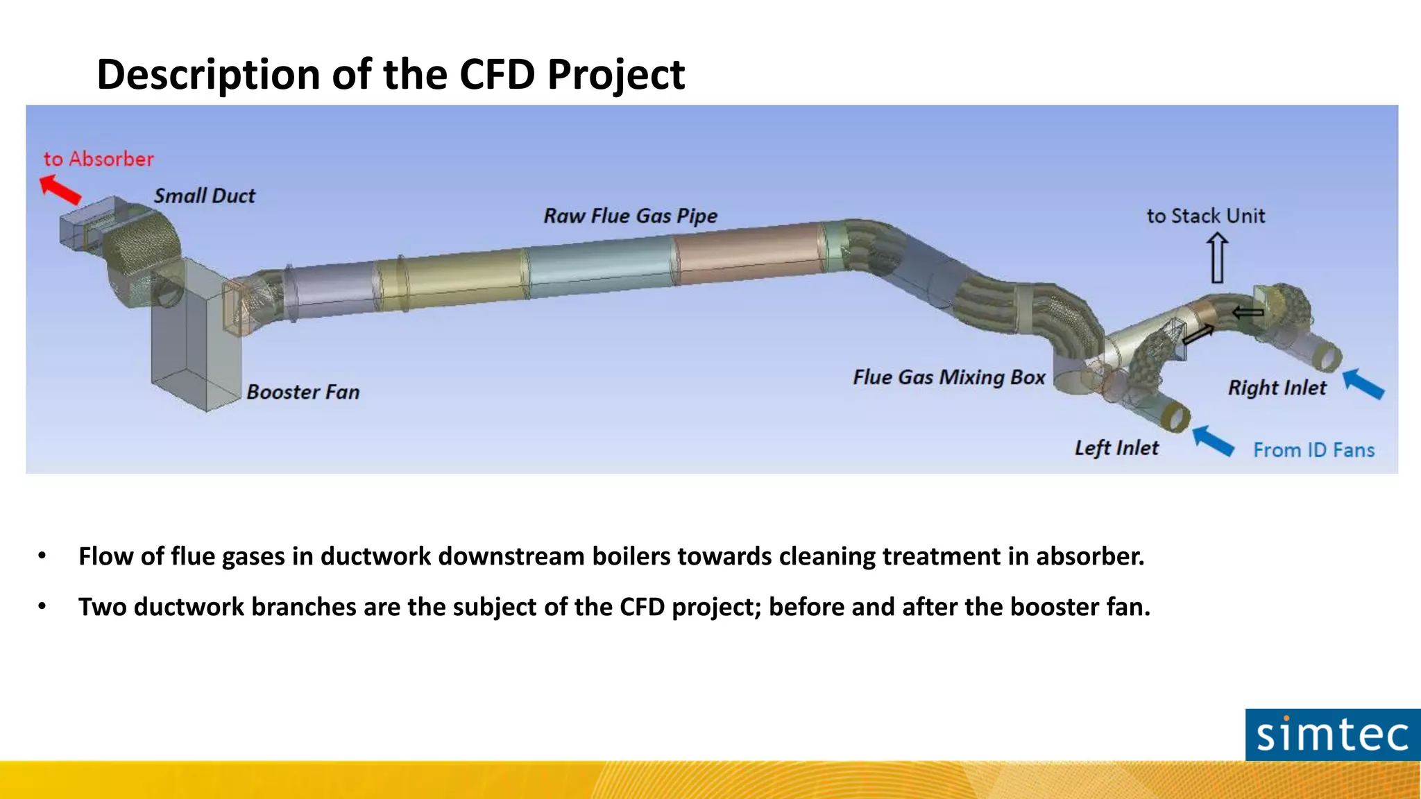
![Appearance of the Problem
• The "small duct" section is prone to Flow–Induced Vibrations (FIV), due to highly unstable and recirculating flow.
• The simulation was run in transient solver due to flow instabilities.
• Pressure drop (including dynamic head) was calculated to 406 [Pa].
10
30
50
70
90
110
130
150
170
40 41 42 43 44 45 46 47
Pst,in[Pa]
Time [s]
Mean=81.33 [Pa]](https://image.slidesharecdn.com/presentationjpeliminatingflowinstabilities-180711091950/75/Eliminating-Flow-Instabilities-and-Reducing-Pressure-Drop-in-a-Pipe-Section-of-a-Power-Unit-4-2048.jpg)


![10
30
50
70
90
110
130
150
170
40 41 42 43 44 45 46 47
Pst,in[Pa]
Time [s]
Validation with ANSYS Fluent
• The instabilities dissappeared and simulation was successfully run in steady–state mode.
• Pressure drop (including dynamic head) was reduced to 225 [Pa].
STEADY STATE achieved!](https://image.slidesharecdn.com/presentationjpeliminatingflowinstabilities-180711091950/75/Eliminating-Flow-Instabilities-and-Reducing-Pressure-Drop-in-a-Pipe-Section-of-a-Power-Unit-9-2048.jpg)
![Conclusions
• A design/optimization question was raised during a real project in a new power station
under construction.
• A quick decision was necessary to resolve a possible FIV issue in the ductwork.
• New product ANSYS Discovery Live was employed and provided on–the–fly insight and
qualitative optimization trends in a few hours.
• The improved design was validated in ANSYS Fluent and was confirmed that eliminates
flow instabilities but also reduces booster fan power by 2 [mbars], translated into
savings for customer (investment and operation cost) of thousands EUROS.](https://image.slidesharecdn.com/presentationjpeliminatingflowinstabilities-180711091950/75/Eliminating-Flow-Instabilities-and-Reducing-Pressure-Drop-in-a-Pipe-Section-of-a-Power-Unit-10-2048.jpg)

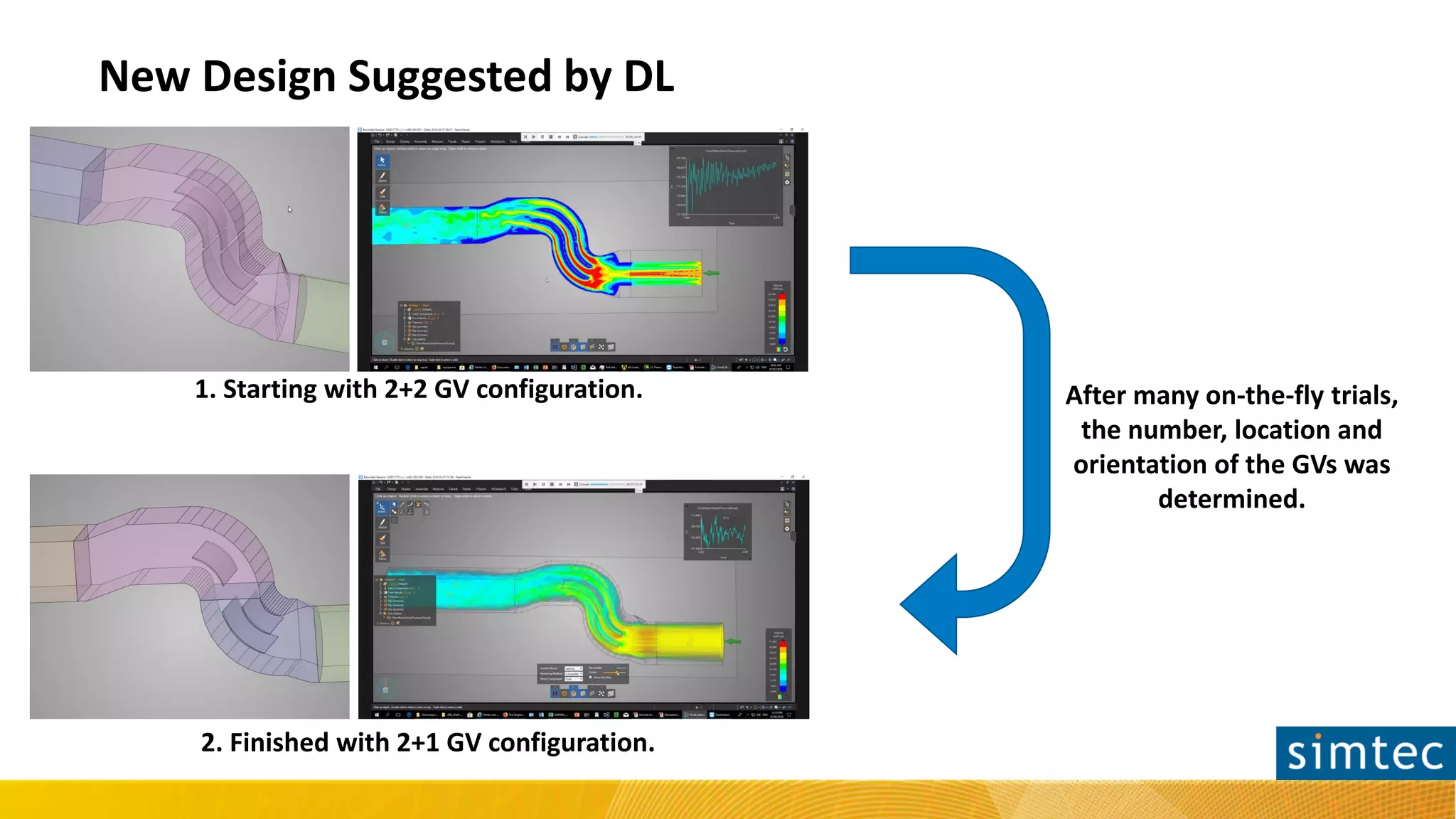
The document describes how ANSYS Discovery Live was used to optimize a pipe section in a power plant that was experiencing unstable and recirculating flow. The pipe section was prone to flow-induced vibrations and had a high pressure drop of 406 Pa. ANSYS Discovery Live was able to quickly test different configurations of guiding vanes on-the-fly to both reduce vibrations and lower the pressure drop. The optimized design of 2 inlet and 1 outlet guiding vane stabilized the flow and reduced the pressure drop to 225 Pa, saving the customer thousands in investment and operation costs.


