Switchgear
• The apparatusused for controlling, regulating and switching on or off the electrical circuit in the
electrical power system is known as switchgear.
• The switches, fuses, circuit breaker, isolator, relays, current and potential transformer, indicating
instruments, lightning arresters and control panels are examples of the switchgear devices
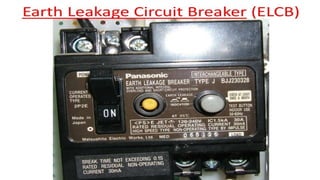
• Generally electrical switchgear rated up to 1KV is termed as low voltage switchgear. The term LV
Switchgear includes low voltage circuit breakers, switches, off load electrical isolators, HRC fuses,
earth leakage circuit breaker, miniature circuit breakers (MCB) and molded case circuit breakers
(MCCB) etc i.e. all the accessories required to protect the LV system. The most common use of LV
switchgear is in LV distribution board.
3.
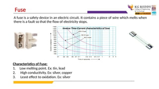
A fuse isa safety device in an electric circuit. It contains a piece of wire which melts when
there is a fault so that the flow of electricity stops.
Fuse
Inverse Time-Current characteristics of fuse
Characteristics of Fuse:
1. Low melting point. Ex: tin, lead
2. High conductivity. Ex: silver, copper
3. Least effect to oxidation. Ex: silver
4.
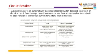
A circuit breakeris an automatically operated electrical switch designed to protect an
electrical circuit from damage caused by excess current from an overload or short circuit.
Its basic function is to interrupt current flow after a fault is detected.
Circuit Breaker
5.
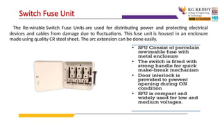
The Re-wirable SwitchFuse Units are used for distributing power and protecting electrical
devices and cables from damage due to fluctuations. This fuse unit is housed in an enclosure
made using quality CR steel sheet. The arc extension can be done easily.
Switch Fuse Unit
6.
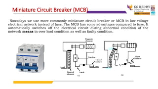
Nowadays we usemore commonly miniature circuit breaker or MCB in low voltage
electrical network instead of fuse. The MCB has some advantages compared to fuse. It
automatically switches off the electrical circuit during abnormal condition of the
network means in over load condition as well as faulty condition.
Miniature Circuit Breaker (MCB)
7.
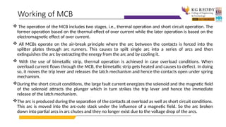
The operationof the MCB includes two stages, i.e., thermal operation and short circuit operation. The
former operation based on the thermal effect of over current while the later operation is based on the
electromagnetic effect of over current.
All MCBs operate on the air-break principle where the arc between the contacts is forced into the
splitter plates through arc runners. This causes to spilt single arc into a series of arcs and then
extinguishes the arc by extracting the energy from the arc and by cooling it.
With the use of bimetallic strip, thermal operation is achieved in case overload conditions. When
overload current flows through the MCB, the bimetallic strip gets heated and causes to deflect. In doing
so, it moves the trip lever and releases the latch mechanism and hence the contacts open under spring
mechanism.
During the short circuit conditions, the large fault current energizes the solenoid and the magnetic field
of the solenoid attracts the plunger which in turn strikes the trip lever and hence the immediate
release of the latch mechanism.
The arc is produced during the separation of the contacts at overload as well as short circuit conditions.
This arc is moved into the arc-cute stack under the influence of a magnetic field. So the arc broken
down into partial arcs in arc chutes and they no longer exist due to the voltage drop of the arcs.
Working of MCB
9.
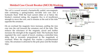
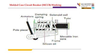
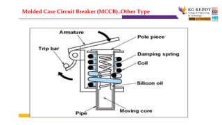
The coil iswound around a hermetically sealed, non-magnetic
tube containing a spring-loaded, movable iron core and a
hydraulic fluid. With the load current either at or below the
breaker's nominal rating, the magnetic flux is of insufficient
strength to move the core, and it remains at the end of the tube
opposite the armature.
On an overload the magnetic force increases, pulling the iron
core into the coil forward the armature end of the tube. This
reduces the reluctance of the magnetic circuit and further
increases the strength of the magnetic field. The hydraulic fluid
regulated the core's speed of travel, creating a controlled time
delay that is inversely proportional to the magnitude of
overload. When the magnetic flux reaches a predetermined
value, the armature is attracted to the pole piece and the breaker
trips.
Molded Case Circuit Breaker (MCCB) Working
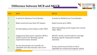
S.No MCB MCCB
1It stands for Miniature Circuit Breaker. It stands for Molded Case Circuit Breaker.
2 Rated current not more than 125 Ampere. Rated Current up to 1600A
3 Its interrupting current rating is under 10KA
Their interrupting current ranges from around
10KA -85KA
4
Judging from their power capacities, MCB is
mainly used for low Breaking capacity
requirement mainly domestic.
MCCB is mainly used for both low and high
Breaking capacity requirements mainly
industrial.
5
Its trip characteristics are normally not
adjustable since they basically cater to low
circuits.
Its trip current may be fixed as well as
adjustable for overload and magnetic setting.
Difference between MCB and MCCB
Wires and Cables
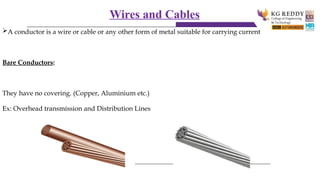
Aconductor is a wire or cable or any other form of metal suitable for carrying current
Bare Conductors:
They have no covering. (Copper, Aluminium etc.)
Ex: Overhead transmission and Distribution Lines
21.
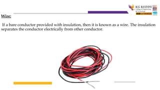
Wire:
If a bareconductor provided with insulation, then it is known as a wire. The insulation
separates the conductor electrically from other conductor.
22.
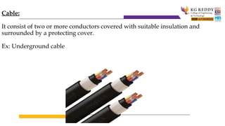
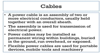
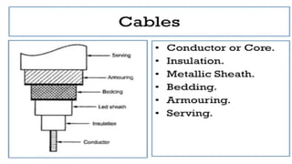
Cable:
It consist oftwo or more conductors covered with suitable insulation and
surrounded by a protecting cover.
Ex: Underground cable
23.
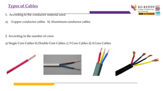
Types of Cables
1.According to the conductor material used
a) Copper conductor cables b) Aluminium conductor cables
2. According to the number of cores
a) Single Core Cables b) Double Core Cables c) 3 Core Cables d) 4 Core Cables
24.
Types of Cables
1.According to the conductor material used
a) Copper conductor cables b) Aluminium conductor cables
2. According to the number of cores
a) Single Core Cables b) Double Core Cables c) 3 Core Cables d) 4 Core Cables
25.
Types of Cables
1.According to the conductor material used
a) Copper conductor cables b) Aluminium conductor cables
2. According to the number of cores
a) Single Core Cables b) Double Core Cables c) 3 Core Cables d) 4 Core Cables
26.
Types of Cables
1.According to the conductor material used
a) Copper conductor cables b) Aluminium conductor cables
2. According to the number of cores
a) Single Core Cables b) Double Core Cables c) 3 Core Cables d) 4 Core Cables
27.
Types of Cables
1.According to the conductor material used
a) Copper conductor cables b) Aluminium conductor cables
2. According to the number of cores
a) Single Core Cables b) Double Core Cables c) 3 Core Cables d) 4 Core Cables
28.
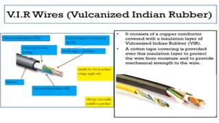
3. According tothe type of insulation
a) Vulcanized Indian Rubber (VIR) Insulated Cables
29.
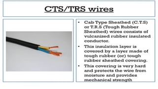
b) Tough RubberSheathed (TRS) or Cable Tyre Sheathed(CTS )
Cables
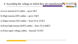
4. According thevoltage at which they are manufactured
a) Low tension (LT) cables – up to 1KV
b) High tension (HT) cables – up to 11KV
c) Super tension (ST) cables – from 22 to 33 KV
d) Extra high tension (EHT) cables – from 33 to 66KV
e) Extra super voltage cables – beyond 132 KV
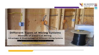
32.
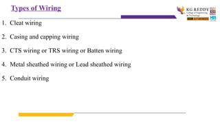
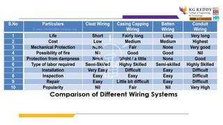
Types of Wiring
1.Cleat wiring
2. Casing and capping wiring
3. CTS wiring or TRS wiring or Batten wiring
4. Metal sheathed wiring or Lead sheathed wiring
5. Conduit wiring
33.
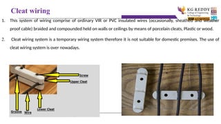
Cleat wiring
1. Thissystem of wiring comprise of ordinary VIR or PVC insulated wires (occasionally, sheathed and weather
proof cable) braided and compounded held on walls or ceilings by means of porcelain cleats, Plastic or wood.
2. Cleat wiring system is a temporary wiring system therefore it is not suitable for domestic premises. The use of
cleat wiring system is over nowadays.
35.
Advantages of cleatwiring
• It is simple and cheap wiring system
• Most suitable for temporary use i.e. under army camping
• As the cables and wires of cleat wiring system is in open air,
Therefore fault in cables can be seen and repair easily.
• Cleat wiring system installation is easy and simple.
• Customization can be easily done in this wiring system e.g. alteration and
addition.
• Inspection is easy and simple.
36.
Disadvantages of cleatwiring
• Appearance is not so good.
• Cleat wiring can’t be use for permanent.
• In this wiring system, the cables and wiring is in open air, therefore,
oil, Steam, humidity, smoke, rain, chemical and acidic effect may
damage the cables and wires.
• it can be only used on 250/440 Volts on low temperature.
• There is always a risk of fire and electric shock.
• it can’t be used in important and sensitive location and places.
• It is not lasting, reliable and sustainable wiring system.
37.
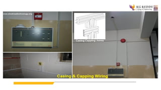
Casing and capping
1.Casing and Capping wiring system was famous wiring system in the past but, it is
considered obsolete this days because of Conduit and sheathed wiring system. The
cables used in this kind of wiring were either VIR or PVC or any other approved
insulated cables.
2. The cables were carried through the wooden casing enclosures. The casing is made up
of a strip of wood with parallel grooves cut length wise so as to accommodate VIR
cables. The grooves were made to separate opposite polarity. the capping (also made of
wood) used to cover the wires and cables installed and fitted in the casing.
39.
Advantages of casing& capping
• It is cheap wiring system as compared to sheathed and conduit wiring
systems.
• It is strong and long-lasting wiring system.
• Customization can be easily done in this wiring system.
• If Phase and Neutral wire is installed in separate slots, then repairing is easy.
• Stay for long time in the field due to strong insulation of capping and casing..
• It stays safe from oil, Steam, smoke and rain.
• No risk of electric shock due to covered wires and cables in casing & capping.
40.
Disadvantages of casing& capping
• There is a high risk of fire in casing & capping wiring system.
• Not suitable in the acidic, alkalies and humidity conditions
• Costly repairing and need more material.
• Material can’t be found easily in the contemporary
• White ants may damage the casing & capping of wood.
41.
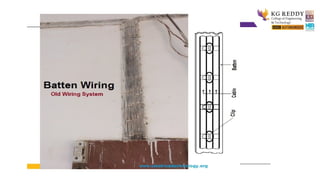
Batten Wiring (CTSor TRS)
• Single core or double core or three core TRS cables with a circular oval shape cables are
used in this kind of wiring. Mostly, single core cables are preferred. TRS cables are
chemical proof, water proof, steam proof, but are slightly affected by lubricating oil.
The TRS cables are run on well seasoned and straight teak wood batten with at least a
thickness of 10mm.
• The cables are held on the wooden batten by means of tinned brass link clips (buckle
clip) already fixed on the batten with brass pins and spaced at an interval of 10cm for
horizontal runs and 15cm for vertical runs.
43.
Advantages of Battenwiring
• Wiring installation is simple and easy
• cheap as compared to other electrical wiring systems
• Paraphrase is good and beautiful
• Repairing is easy
• strong and long-lasting
• Customization can be easily done in this wiring system.
• less chance of leakage current in batten wiring system
44.
Disadvantages of Battenwiring
• Can’t be install in the humidity, Chemical effects, open and outdoor areas.
• High risk of firs
• Not safe from external wear & tear and weather effects (because, the wires are openly
visible to heat, dust, steam and smoke).
• Heavy wires can’t be used in batten wiring system.
• Only suitable below the 250V.
• Need more cables and wires
45.
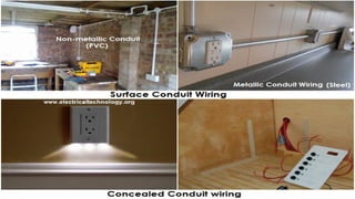
Conduit Wiring
• Thereare two types of conduit wiring according to pipe installation
i) Surface Conduit Wiring
ii) Concealed Conduit Wiring
i) Surface Conduit Wiring
• If conduits installed on roof or wall, It is known as surface conduit wiring. In this
wiring method, we make holes on the surface of wall on equal distances and conduit is
installed then with the help of rawal plugs.
46.
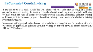
ii) Concealed Conduitwiring
• If the conduits is hidden inside the wall slots with the help of plastering, it is called
concealed conduit wiring. In other words, the electrical wiring system inside wall, roof
or floor with the help of plastic or metallic piping is called concealed conduit wiring.
obliviously, It is the most popular, beautiful, stronger and common electrical wiring
system nowadays.
• In conduit wiring, steel tubes known as conduits are installed on the surface of walls
by means of pipe hooks (surface conduit wiring) or buried in walls under plaster and
VIR or PVC cables.
48.
Advantage of ConduitWiring Systems
• It is the safest wiring system (Concealed conduit wring)
• Appearance is very beautiful (in case of concealed conduit wiring)
• No risk of mechanical wear & tear and fire in case of metallic pipes.
• Customization can be easily done according to the future needs.
• Repairing and maintenance is easy.
• There is no risk of damage the cables insulation
• it is safe from corrosion (in case of PVC conduit) and risk of fire.
• It can be used even in humidity , chemical effect and smoky areas.
• No risk of electric shock (In case of proper earthling and grounding of metallic pipes).
• It is reliable and popular wiring system.
• sustainable and long-lasting wiring system.
49.
Disadvantages of ConduitWiring Systems
• It is expensive wiring system (Due to PVC and Metallic pipes, Additional earthing for
metallic pipes Tee(s) and elbows etc.
• Very hard to find the defects in the wiring.
• installation is not easy and simple.
• Risk of Electric shock (In case of metallic pipes without proper earthing system)
• Very complicated to manage additional connection in the future.
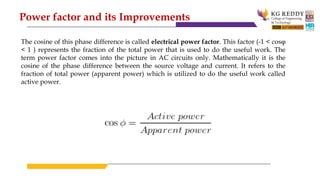
53.
The cosine ofthis phase difference is called electrical power factor. This factor (-1 < cosφ
< 1 ) represents the fraction of the total power that is used to do the useful work. The
term power factor comes into the picture in AC circuits only. Mathematically it is the
cosine of the phase difference between the source voltage and current. It refers to the
fraction of total power (apparent power) which is utilized to do the useful work called
active power.
Power factor and its Improvements
54.
Need for PowerFactor Improvement
Real power is given by P = VIcosφ. The electrical current is inversely proportional to
cosφ for transferring a given amount of power at a certain voltage. Hence higher the pf
lower will be the current flowing. A small current flow requires a less cross-sectional area
of conductors, and thus it saves conductors and money.
From the above relation, we see having poor power factor increases the current flowing
in a conductor and thus copper loss increases. A large voltage drop occurs in the
electrical machines and transmission and distribution lines – which gives very poor
voltage regulation.
Hence, the size and cost of the machine is also reduced.
This is why electrical power factor should be maintained close to unity – it is significantly
cheaper.
55.
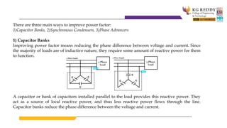
There are threemain ways to improve power factor:
1)Capacitor Banks, 2)Synchronous Condensers, 3)Phase Advancers
1) Capacitor Banks
Improving power factor means reducing the phase difference between voltage and current. Since
the majority of loads are of inductive nature, they require some amount of reactive power for them
to function.
A capacitor or bank of capacitors installed parallel to the load provides this reactive power. They
act as a source of local reactive power, and thus less reactive power flows through the line.
Capacitor banks reduce the phase difference between the voltage and current.
56.
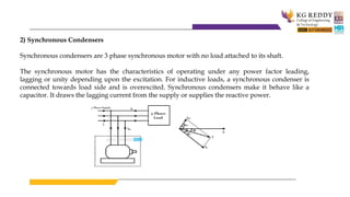
2) Synchronous Condensers
Synchronouscondensers are 3 phase synchronous motor with no load attached to its shaft.
The synchronous motor has the characteristics of operating under any power factor leading,
lagging or unity depending upon the excitation. For inductive loads, a synchronous condenser is
connected towards load side and is overexcited. Synchronous condensers make it behave like a
capacitor. It draws the lagging current from the supply or supplies the reactive power.
57.
3) Phase Advancers
Thisis an AC exciter mainly used to improve the PF of an induction motor.
They are mounted on the shaft of the motor and are connected to the rotor circuit of the
motor. It improves the power factor by providing the exciting ampere turns to produce
the required flux at the given slip frequency.
Further, if ampere-turns increase, it can be made to operate at leading power factor.
58.
Important Questions forInternal/End Examination of Unit V:
1.What are the different types of wires and cables?
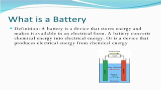
2. Give applications of the primary and secondary batteries.
3. What are the drawbacks of low power factor?
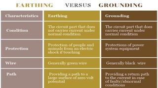
4. What is the necessity of Earthing in domestic buildings?
5. What is the difference between fuse unit and switch fuse unit?
6. What is the difference between MCB and MCCB, Justify with schematic diagrams?
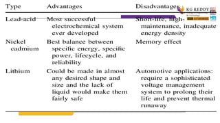
7. What are the types of batteries? Explain.
8. What are the disadvantages of low power factor? Discuss the improvement of low power factor.
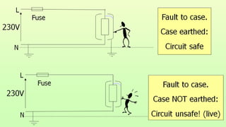
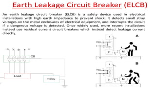
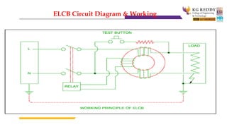
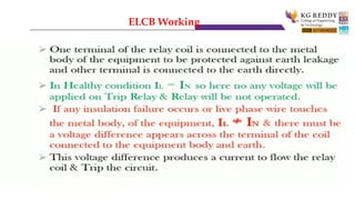
9. What is ELCB? Explain the working principle of ELCB.Mention advantages and disadvantages
of ELCB