Download to read offline
![V Jaya Prasad, K V Ravi Sankar, Dr N Mohanarao, Dr S Kamaluddin / International Journal
of Engineering Research and Applications (IJERA) ISSN: 2248-9622 www.ijera.com
Vol. 3, Issue 1, January -February 2013, pp.891-897
Development of Mechanical properties of an Al–Mg alloy through
Equi-Channel Angular Pressing
V Jaya Prasad1,K V Ravi Sankar2 ,Dr N Mohanarao3, Dr S Kamaluddin4
1
GITAM University, Vishakapatnam 530045, AP, India
2
Andhra Loyola Institute of Engg & Technology,Vijayawada 520008, AP, India
3
JNTU Kakinada 533003 AP, India
4
GITAM University, Vishakapatnam 530045, AP, India
Abstract
Equal channel angular Pressing (ECAP) second channel. The material is de- formed by shear
is an innovative technique for developing as it crosses the intersection channel. The billet
ultrafine-grained microstructures first developed deformed by ECAE retains the same cross-sectional
by Segal et al in 1981 in the former Soviet Union. area, so it is possible to repeat the process over
The ECAP method consists of two channels that several cy- cles.
intersect at an angle, generally comprised between Some authors have studied different routes to process
90◦ and 135◦ . The deformation is produced by the material by ECAE [2,3], where some of them are:
shear as the billet is extruded through the route A, the specimen orientation is kept the same in
channels. One of the geometrical properties of the successive pas-sages; route B, the specimen is
rotated 90◦ around its axis between consecutive
process is that the cross-section of the billet
remains constant and so, it is possible to repeat
the process over many cycles. Therefore, very high passages and route C, the specimen is rotated 180◦
plastic strains can be accumulated in the billet. around its axis between consecutive passages, where
Thus, the ECAP process allows us to produce the microstructure obtained is different depending on
ultrafine-grained materials and hence to improve the processing route [2,4].
the mechanical properties of the material. In this study, tensile strength and Vickers Hardness
This work presents a study of the mechanical and are studied in Al–Mg alloy. The ECAE process was
optical properties of the AA5083 processed by repeated five times through route C. Moreover, the
equal channel angular extrusion. Vickers present work examines strengthening as related to
microhardness and tensile tests were carried out grain size. In order to do this, the evolution of the
after processing the AA5083 up to N = 5 at room microstructure was studied by means of optical
temperature. The improvement obtained in microscopy.
mechanical properties is shown.
Keywords: ECAP; Microstructure; Vickers 2. Experimental procedure
microhardness; Tensile test; Optical microscopy As was previously mentioned, the
aluminium alloy 5083 (Al–Mg) was used for this
study. The alloy was analyzed by
1. Introduction
Ultra fine-grained materials are currently of
great scien- tific interest due to their unusual
mechanical properties. One method for developing
ultra fine-grained materials in metal alloys is equal
channel angular extrusion or Pressing (ECAE), which
initially was developed by Segal et al. [1].
In this process, the cross section of the extruded
material is not modified significantly, so there is no
geometric restric- tion on the deformation that could
be achieved. Although a restriction obviously exists
as a consequence of the cracks, which appear in the
surface and may damage the billet, as shown in Fig.
1.
The ECAE method consists of two channels that
Fig. 1. Billets with cracks in the surface after N = 6
intersect at an angle, usually between 90◦ and 135◦ . A ECAE passages.
billet of material is placed into one of the channels.
Then, the billet is extruded with a punch into the
891 | P a g e](https://image.slidesharecdn.com/ei31891897-130220233322-phpapp02/85/Ei31891897-1-320.jpg)
![V Jaya Prasad, K V Ravi Sankar, Dr N Mohanarao, Dr S Kamaluddin / International Journal
of Engineering Research and Applications (IJERA) ISSN: 2248-9622 www.ijera.com
Vol. 3, Issue 1, January -February 2013, pp.891-897
Table 1
Chemical composition of AA5083
%
Zn 0.02
Mg 4.40
Cu 0.05
Si 0.35
Mn 0.093
Fe 0.20
Cr 0.12
Zr 0.02 Fig. 4. Tension test for N = 0.
Ti 0.01
ICP-AES. The chemical composition of the alloy is
shown in Table 1.
The die used for ECAE consists of two channels
of equal cross section intersecting at an angle of 90◦ as
shown in Fig. 2.
The friction during the extrusion was minimized
using MoS2 lubricant for both the rods and the die.
The ECAE process was carried out at room
temperature and during the extrusion, the punch
speed was 10 mm/min.
Fig. 2. ECAE process and considered zones within the
billet, from reference [6].
Fig. 5. Tension test for N = 1.
Fig. 3. Machined specimens for tensile test.
Table 2
Vickers microhardness measured with a load of 1
kg and with duration of the tests of 15 s
Zone 1 2 3 4 5
N1, HV 118 132.7 133.7 134 136. Fig. 6. Tension test for N = 2.
N2, HV 131.7 144.2 145 140.2 118
5
N3, HV 138.7 155 152.5 151.5 133.
N4, HV 146.5 163 157 163.5 146
5
N5, HV 150 153.7 158 156.5 149.
5
Microhardness measured after 1, 2, 3, 4 and 5 ECAE
passages in different zones within the processed billet.
Fig. 7. Tension test for N = 3
892 | P a g e](https://image.slidesharecdn.com/ei31891897-130220233322-phpapp02/85/Ei31891897-2-320.jpg)
![V Jaya Prasad, K V Ravi Sankar, Dr N Mohanarao, Dr S Kamaluddin / International Journal
of Engineering Research and Applications (IJERA) ISSN: 2248-9622 www.ijera.com
Vol. 3, Issue 1, January -February 2013, pp.891-897
3), zone 3 (central zone), zone 4 (between
zone Each billet was extruded up to five
times, since cracks appeared at the end of
the deformed specimen as shown in Fig. 1.
The dimensions of the billet were 10 mm in
diameter and 80 mm in length.
The deformed billets were cut in the
extrusion axis direc- tion to perform the
Vickers measurements, and polished, in
order to analyze the microstructure by
optical microscopy. Tensile tests were
carried out to characterize the mechanical
properties of the deformed billets.
The microhardness measurements were
obtained with a Micromet microhardness
tester. A Vickers diamond pyrami- dal
indenter was used. The load used was 1 kg
and the duration of the tests was 15 s. The
processed billets were machined af- ter each
ECAE passage, as shown in Fig. 3, in order
Fig. 9. Tension test for N = 5.
to attain the flow stress curves shown in
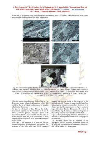
Optical images, showing the deformed Figs. 4–9.
grains developed after the different ECAE Afterwards, the polished samples were
passages, were taken of different zones etched using the
within the processed billet as shown in Figs. Barker attack. [5].
10–11. The different zones are: zone 1
(inner radius), zone 2 (between zone 1 and
Fig. 10. Optical micrographs showing the original grains in different zones within the unprocessed billet.
893 | P a g e](https://image.slidesharecdn.com/ei31891897-130220233322-phpapp02/85/Ei31891897-3-320.jpg)
![V Jaya Prasad, K V Ravi Sankar, Dr N Mohanarao, Dr S Kamaluddin / International Journal
of Engineering Research and Applications (IJERA) ISSN: 2248-9622 www.ijera.com
Vol. 3, Issue 1, January -February 2013, pp.891-897
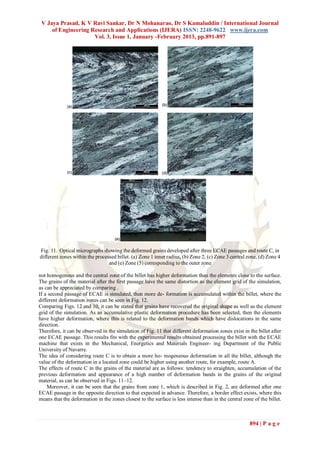
Table 3 shows the Vickers measurements on the Table 6
central position (zone 3), which presents the highest Yield strength with the number of
deformation values. passes
N Yield strength
It can be observed in Fig. 13 that the microhardness 0 (MPa)
167.3
value increases with the number of passes. The 1 442.25
highest increase in hardness occurs when the billet is 2 481.5
processed by ECAE once (N = 1). From N =0 to N = 3 481.8
1, the microhardness increases 54 HV. On the other 4 482.6
5 504
hand, from N =1 to N = 5, a low increase in hardness
is observed.The microhardness in the zone
corresponding to the inner radius of different billets . / Journal of Materials Processing Technology 162–
are shown in Table 4 and the values of microhardness 16B. Huarte et al 3 (2005) 317–326 325
measured in the zone corresponding to the outer
radius are shown in Table 5. 6. Conclusions
Optical and mechanical properties of
Table 3 processed billets by ECAE have been studied in this
Vickers microhardness with the number of passes work. The structure of the processed billets has
been examined by employing optical microscopy in
N HV
different zones of the billet. The experimen- tally
0 79.5 obtained results have been compared to those
1 133.75 obtained using FEM simulations.
2 145 The experimental results fit well with the simulated
3 152.5 results in all the deformation zones of the processed
4 157 material. The highest deformation is achieved in the
5 158 middle of the billet. The deformation bands in the
central zone of the processed billets are easily
Table 4 observed not only in the micrographs but also in the
Vickers microhardness of the inner radius of the
different billet
HV 118 118 138.7
146
150
Table 5
Vickers microhardness of the outer radius of the
different billet
HV 136.5 131.7 133.5
Fig. 13. Vickers microhardness vs. number of
146.5 149.5
passes
Vickers microhardness is higher in the central
position, due to the high plastic deformation achieved
in this position, which agrees with the results from
reference [6].
The billet processed the first time presents in the
inner radius a value of 118 HV. The second pass, in
which this position corresponds to the outer radius,
presents the same value of microhardness. The next
pass presents a higher value of microhardness due to the
higher deformation achieved with the different
passages. The value of the microhardness in this
Fig. 14. Yield Strength vs. the number of
position of the billet processed four and five times
passes
increases slightly.
The tension tests were carried out with the
machined billets. The yield strength increases with the
number of passes, in the same way as microhardness.
The values of yield strength are given by Table 6.
896 | P a g e](https://image.slidesharecdn.com/ei31891897-130220233322-phpapp02/85/Ei31891897-6-320.jpg)
![V Jaya Prasad, K V Ravi Sankar, Dr N Mohanarao, Dr S Kamaluddin / International Journal
of Engineering Research and Applications (IJERA) ISSN: 2248-9622 www.ijera.com
Vol. 3, Issue 1, January -February 2013, pp.891-897
Just as with microhardness, the highest increase Y. Zahra, Z. Metallk 71 (1980) 231.
occurs when the billet is processed by ECAE first [14] L. K. Berg and J. GjØnnes, Acta Mater 49
time. The billets with 2, 3, 4 and 5 passes present a (2001) 3443-3451.
yield strength which turn out to be very similar, as
can be observed in Fig. 14.
deformation contour map of the simulations.
Microhardness and tension tests were carried out with
the processed billets. The values of both parameters
increase with the number of ECAE passages. The
highest increase occurs from N = 0 to N = 1. In the
different billets, the highest value of microhardness was
achieved in the middle of the billet, where this agrees
well with the highest deformations achieved in this
zone of the billet. This means that the higher the
deformation values reached in the material are, the
higher the microhard- ness and yield stress reached in
the tension test are.
References
[1] V. M. Segal, “Engineering and
Commercialization of Equal Channel Angular
Extrusion,” Mater. Sci. Eng., A 386, 269–276
(2004).
[2] R. Z. Valiev, R. K. Islamgaliev, and I. V.
Alexandrov,“Bulk Nanostructured Materials
from Severe Plastic Deformation,” Prog.
Mater. Sci. 45, 103–189 (2000).
[3] M. Kamachi, M. Furukawa, Z. Horita, and T.
G. Langdon,“Equal-Channel Angular
Pressing Using Plate Samples,” Mater. Sci.
Eng., A 361, 258–266 (2003).
[4] I.Nikulin, R. Kaibyshev, and T. Sakai,
“Superplasticity in a 7055 Aluminum Alloy
Processed by ECAE and Sub sequent
Isothermal Rolling,” Mater. Sci. Eng., A
407,62–70 (2005).
[5]. Z. Horita, M. Furukawa, M. Nemoto, and T.
G. Langdon,“Development of Fine Grained
Structures Using Severe Plastic
Deformation,” Mater. Sci. Technol. 16,
1239–1245 (2000)
[6] L.F. Mondolfo, Int. Metall. Rev. 153 (1971)
95.
[7] I.J. Polmear, “light Alloys”, Metall. and Mater.
Sci. Series, 3rd Edition, London (1995). [8] J.
Lendvai, Mater. Sci. Forum 43 (1996) 217-
222.
[9] A. Deschamps, F. Livet and Y. Bréchet, Acta
Mater 47 (1999) 281.
[10] P. Guyot and L. Cottignies, Acta Mater 44
(10) (1996) 4161-4167.
[11] J. C. Werenskiold and A. Deschamps, Mater
Sci. Eng. A, Struct. Mater: Prop. Microstruc.
Process 293 (2000) 267-274.
[12] J. D. Embury and A. Deschamps, Sc. Mater 49
(2003) 927-932.
[13] H. P. Degischer, W. Locom, A. Zahra and C.
897 | P a g e](https://image.slidesharecdn.com/ei31891897-130220233322-phpapp02/85/Ei31891897-7-320.jpg)

This study investigates the mechanical properties of an Al-Mg alloy (AA5083) processed through equal channel angular pressing (ECAP) to develop ultrafine-grained microstructures. The results indicate that the mechanical properties, such as tensile strength and Vickers microhardness, improve significantly with the number of processing passes, particularly after the first pass. Optical microscopy analyses reveal non-uniform deformation across the billet, with the central zone exhibiting the highest plastic strain and mechanical properties.