Download to read offline
![2 / 4 P/N 3100558 • REV 04 • REB 30JAN13
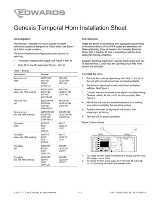
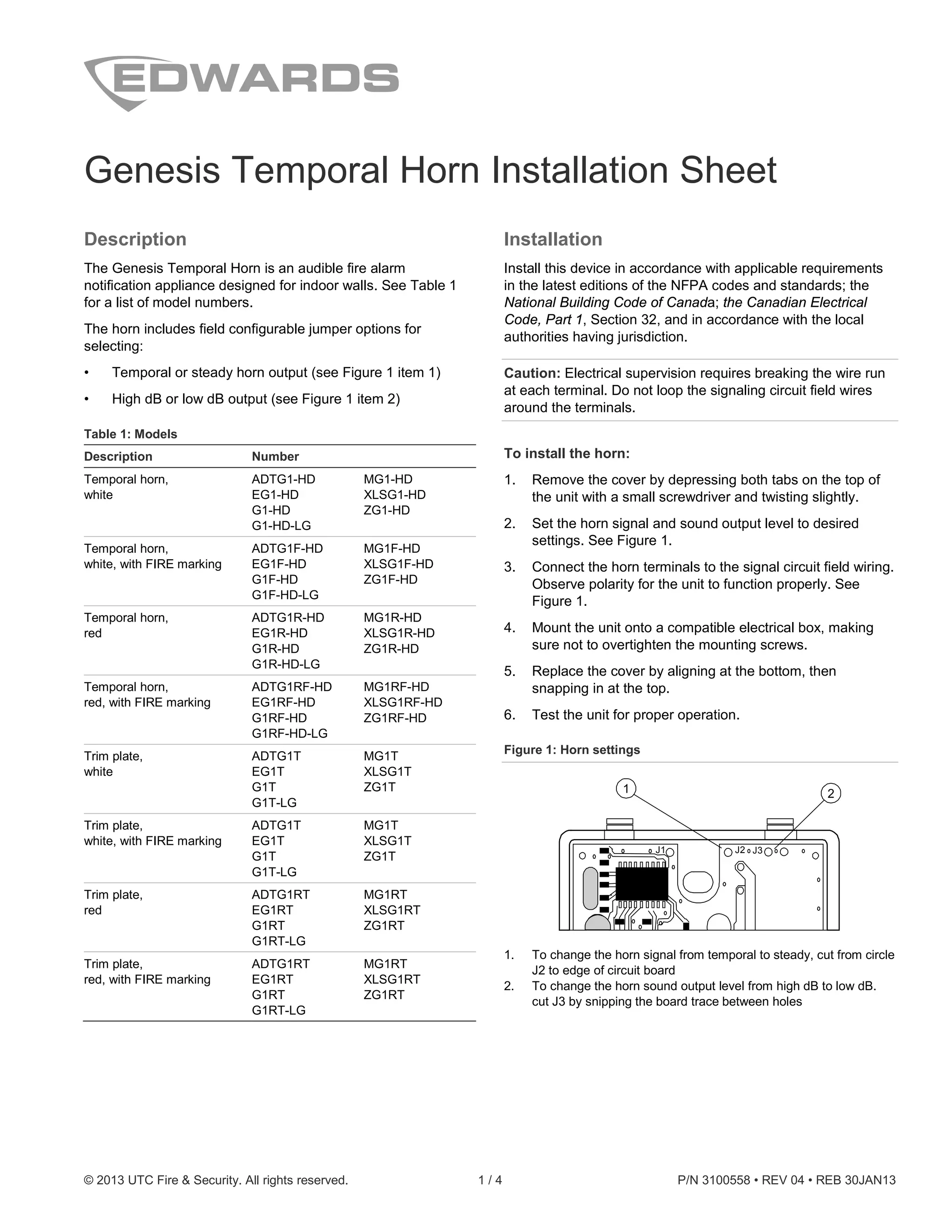
Figure 2: Wiring diagram
1 2
-
+
1. From NAC output
2. To next NAC output
Note: Polarity is shown in the alarm condition.
Maintenance
Caution: To maintain the required agency listings, do not
change factory applied finishes.
This unit is not serviceable or repairable. Should the unit fail to
operate, contact the supplier for replacement.
Perform a visual inspection and an operational test twice a
year or as directed by the local authority having jurisdiction.
Table 2: Sound level output (dBA)
Signal and voltage Low High
Temporal 16 VDC 76.0 81.4
24 VDC 79.4 84.4
33 VDC 82.1 86.3
Continuous 16 VDC 80.1 85.5
24 VDC 83.5 88.6
33 VDC 86.5 90.4
UL 464: Sound level output at 10 ft. (3.05 m) measured in a
reverberant room.
Table 3: Sound level output (dBA, temporal tone, peak)
Tonal and voltage High
16 VDC 98.8
24 VDC 102.7
33 VDC 104.3
16 VFWR 102.4
24 VFWR 105.0
33 VFWR 106.9
CAN/ULC-S525: Meets or exceeds 85 dBA in an anechoic chamber at
10 ft. (3.05 m)
Table 4: Operating current in RMS (A)
Voltage High Low
16 VDC 0.026 0.019
24 VDC 0.036 0.027
33 VDC 0.041 0.033
16 VFWR 0.051 0.037
24 VFWR 0.069 0.052
33 VFWR 0.076 0.070
VDC = Volts direct current, regulated and filtered
VFWR = Volts full wave rectified
Table 5: Audible directional characteristics (horizontal pattern)
Angle (°) [1] Sound output (dBA) [2]
−90 94
−45 97 (−6)
−30 100 (−3 )
90 103
30 100 (3 )
45 97 (6 )
90 96
[1] Angles are measured from a perpendicular axis; positive angles to
the right
[2] Peak output at 24 VDC, set for temporal tone.
Table 6: Audible directional characteristics (vertical pattern)
Angle (°) [1] Sound output (dBA) [2]
−90 94
−40 97 (−6)
−25 100 (−3)
90 103 dBA
35 100 (3)
45 97 (6)
90 96
[1] Angles are measured from a perpendicular axis; positive angles are
up.
[2] Peak output at 24 VDC, set for temporal tone.](https://image.slidesharecdn.com/eg1hd-150526143222-lva1-app6892/85/Edwards-Signaling-EG1HD-Installation-Manual-2-320.jpg)


The document provides installation instructions and specifications for the Genesis Temporal Horn, an audible fire alarm notification device designed for indoor use. It details model numbers, installation procedures, configurable options, maintenance requirements, sound level outputs, and compliance with safety standards. The document emphasizes the importance of following local regulations and performing regular tests for proper operation.


