Downloaded 28 times

![DETECTOR HOUSING MATERIAL— -- OR --
CF8M stainless steel (castable 316 equivalent). 0539 II 2 G
EEx d [ib] IIC T4-T5
CONDUIT ENTRY OPTIONS— DEMKO 01 ATEX 129485X.
Two entries, 3/4 inch NPT or 25 mm. T5 (Tamb –40°C to +40°C)
T4 (Tamb –40°C to +75°C)
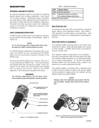
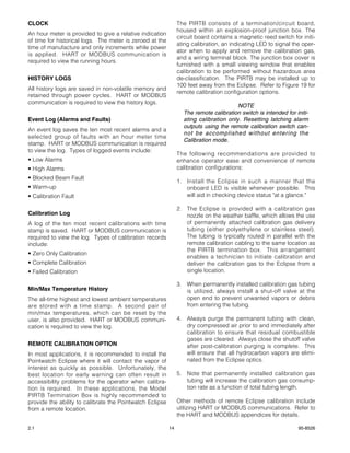
HART COMMUNICATION PORT— IP66.
Explosion-proof (FM/CSA)
Intrinsically safe (CENELEC/CE). Special Conditions for Safe Use (‘X’):
• The following warning is on the product:
OPTICS PROTECTION—
Three-layer weather baffle assembly is Polythalimide Warning: Do not open when an explosive gas atmo-
plastic, UV-resistant, static dissipating black. sphere may be present.
Optional internal hydrophobic filter is recommended For ambient temperature above 60°C use field
for areas with high levels of airborne particulates or wiring suitable for maximum ambient temperature.
humidity. For temperature below –10°C use suitable field
wiring for the lowest temperature.
WIRING— • Cable, bushings and the conduit entries shall be of
Field wiring screw terminals are UL/CSA rated for up a type already certified according to relevant CEN-
to 14 AWG wire, and are DIN/VDE rated for 2.5 mm2 ELEC standard, so the protection principle
wire. Screw terminal required torque range is 3.5–4.4 employed will not be impaired.
in.-lbs. (0.4-0.5 N·m).
• Blanking elements shall be used for closing unused
ELECTRICAL SAFETY CLASSIFICATION— holes and they shall be certified to the protection
Installation Category (Overvoltage Category) II principle employed. The blanking elements or the
& Pollution Degree 2 per ANSI/ISA-S82.02.01, device may only be removed with the aid of a tool.
EN 61010-1 & IEC 61010-1. • The field wiring connections are terminals certified
for increased safety according to the CENELEC
CERTIFICATIONS— standard EN50019 and is certified for a single wire
FM & CSA: Class I, Div. 1, Groups C & D (T4). in size from 0.2 to 2.5 mm2, (two conductors with
Class I, Div. 2, Groups A, B, C & D (T4). same cross section 02. to 0.75 mm2). The torque
Performance verified. 0.4 to 0.5 Nm.
• The Eclipse metal housing must be electrically con-
NOTE nected to earth ground.
Approval of the Model PIRECL does not include
or imply approval of the apparatus to which the • The temperature code is linked to the ambient tem-
detector may be connected and which processes perature as the following:
the electronic signal for eventual end use. Code T5 for use in Tamb from –40°C to +50°C
Code T4 for use in Tamb from –40°C to +75°C
NOTE
This Approval does not include or imply Approval • The terminal compartment for Eclipse without relays
of the communications protocol or functions pro- is designed for either an increased safety “e” termi-
vided by the software of this instrument or of the nation or a flameproof “d” termination of the supply
communications apparatus or software connect- cable. If a flameproof connection is chosen, then a
ed to this instrument. CENELEC certified cable entry device certified to
EN50018 must be used. The Eclipse with relays
CENELEC: 0539 II 2 G requires Ex d cable entry devices only.
EEx de [ib] IIC T4-T5
DEMKO 01 ATEX 129485X.
(Performance verified.)
T5 (Tamb –40°C to +40°C)
T4 (Tamb –40°C to +75°C)
IP66.
2.1 4 95-8526](https://image.slidesharecdn.com/eclipsemanual-120917080916-phpapp01/85/Eclipse-manual-4-320.jpg)

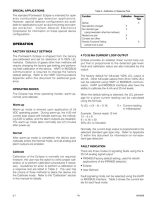
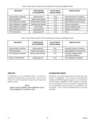
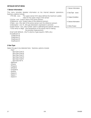

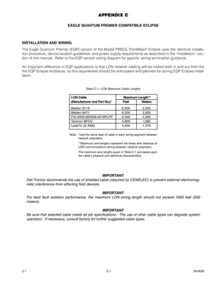
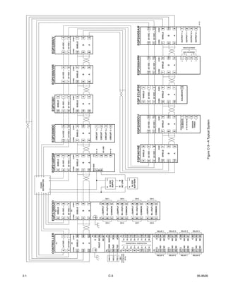

The document provides instructions for operating an infrared hydrocarbon gas detector. It can be used as a standalone detector or as part of a larger safety system. It continuously monitors combustible gases from 0-100% LEL and has configurations that output analog signals or provide alarm relays. It operates by measuring the absorption of infrared light by hydrocarbon gases in its measurement chamber.


