SlideShare a Scribd company logo
1 of 4
Structural Designon CarportCanopy Considering
Wind Tunnel Testing
Givenwindtunnel analysisconducted byCPP,we canconsiderthe additionof a deflectoruponthe PV
structure inorder to reduce the windloaduponthe structural systemandreduce the weightof purlins,
columns,andbeamsthemselves.
Usinga providedRISA 3Dfile,we cananalyze outvariousconfigurationsof the structure inordertofind
the optimal membersthatisbothstructurallysoundandeconomicallybeneficial.
GENERAL CONFIGURATION
The configurationthatthe newdesignwill implementisasfollows inFigure 1(pisfor panels):
The opencircles( ) representthe endpointsof individualpurlins. Variationsof thispatterncanbe used
dependingonspecial availabilityandnumber of baysneeded.
Columns
The original columndimensions(HSS12x8x8) we have usedwithinthe DSA plansare sufficientforthe
newdesign. These shouldnotbe changedasthisis a commonspec forthissteel type andwill keepthe
material purchasingeasyand efficient.
Beams
Givena more accurate testmodel fromthe windtunnel report,we can reduce the dimensionsof a
beamto W14x34. This will be slightlylighterandcheaperthanthe original W
3p 10p 2p 8p 2p 8p 2p 8p 2p 7p 3p
Fig. 1 – Sample configuration of purlin and beam
supports for canopy (p is for panels)
Purlins
To minimize weightandtomaximize savings,we wanttochoose cold-formedpurlinswiththinnercross-
section.The model will workwithall 14gamemberpurlins(12CS4x070);however,tofurtherdecreaseto
cost and weight,we canutilize a16ga memberonselectmembersof the structure.The structure does
not passthe code checkif all purlinswere ata 16ga thickness.
Giventhe windtunnel testmodel,we cansee thatmost of the greaterloadswill be concentratedon
eitherendsof structure.Thisisindicated belowwithwindloadcase A inbothup and downdirections.
We can change the leftmostandrightmostpurlinsinto a stronger14ga purlins,while the middle purlins
not supportingthe critical loadscanhave a 16ga thickness. Specifically,the twoleftmostandthe two
rightmostpurlinswillbe the only4purlinlineswitha14ga thickness.
Fig. 2 – Side view of wind load case A
Fig. 3 – Purlin set-up
Bracing
If purlinsdonot satisfythe D/Cratio, bracingscan be adjustedtoaccommodate the momentdistributed
across the member. For example, one of the bracing on the top left was moved towards the middle to
account fora large momentconcentratedtowardsthe middle.
MEMBER SPECS
Purlins
Type Thickness Strength Weight
12CS4x070 14ga (0.070in) 55 ksi 5.002 lb/ft
12CS4x056 16ga (0.056in) 65 ksi 3.934 lb/ft
Beams
Type Thickness Strength Weight
W14x37 F: 0.455 in , W: 0.285 in 50 ksi 344.028 lb/ft
Columns
Type Thickness Strength Weight
HSS12x8x8 0.465 in 56 ksi 58.528 lb/ft
SAVINGS PER BAY
Each bay stretchestoabout 34.75 feetperbay.There are 12 total purlins.
Cases Weightperbay
Case 1: All purlins 14ga 2805.83lb
Case 2: 4 purlins14ga, 8 purlins16ga 1788.93 lb
Thisresultsina difference of 296.904 lbof savedforthe new purlindimensions
Fig. 4 – Adjustment of bracing
RESULTS
Afterusingthe membersizesandadjustmentsfromabove,we can achieve the followingD/Cresultsfor
the structure:
Fig. 5 – D/C for beams and columns
Fig. 6 – D/C for beams and columns

More Related Content

Similar to Structural Design Optimization of a Carport Canopy Considering Wind Loads

Engineering science lesson 6 2
Engineering science lesson 6 2Engineering science lesson 6 2
Engineering science lesson 6 2Shahid Aaqil
 
Seismic optimization of an I shaped shear link damper in EBF and CBF systems
Seismic optimization of an I shaped shear link damper in EBF and CBF systemsSeismic optimization of an I shaped shear link damper in EBF and CBF systems
Seismic optimization of an I shaped shear link damper in EBF and CBF systemsIRJET Journal
 
Pile cap two pile laod 50 t desigh and drawing
Pile cap  two pile laod 50 t  desigh and drawingPile cap  two pile laod 50 t  desigh and drawing
Pile cap two pile laod 50 t desigh and drawingRAJESH JAIN
 
Two pile group
Two pile groupTwo pile group
Two pile groupNaOzas
 
IRJET- Impact Resistances of Hybrid Steel Truss Beams
IRJET-  	  Impact Resistances of Hybrid Steel Truss BeamsIRJET-  	  Impact Resistances of Hybrid Steel Truss Beams
IRJET- Impact Resistances of Hybrid Steel Truss BeamsIRJET Journal
 
IRJET- Buckling Analysis of Corrugated Hollow Columns using Trapezoidal and S...
IRJET- Buckling Analysis of Corrugated Hollow Columns using Trapezoidal and S...IRJET- Buckling Analysis of Corrugated Hollow Columns using Trapezoidal and S...
IRJET- Buckling Analysis of Corrugated Hollow Columns using Trapezoidal and S...IRJET Journal
 
IRJET- Analytical Behaviour of Stiffened and Unstiffened CFDST Short Column
IRJET-  	  Analytical Behaviour of Stiffened and Unstiffened CFDST Short ColumnIRJET-  	  Analytical Behaviour of Stiffened and Unstiffened CFDST Short Column
IRJET- Analytical Behaviour of Stiffened and Unstiffened CFDST Short ColumnIRJET Journal
 
Development of Design Tables For A –Frame Trusses As Per Is 800-2007
Development of Design Tables For A –Frame Trusses As Per Is 800-2007Development of Design Tables For A –Frame Trusses As Per Is 800-2007
Development of Design Tables For A –Frame Trusses As Per Is 800-2007IRJET Journal
 
Design of short columns using helical reinforcement
Design of short columns using helical reinforcementDesign of short columns using helical reinforcement
Design of short columns using helical reinforcementshivam gautam
 
Design and Standardization of Toggle Jack
Design and Standardization of Toggle JackDesign and Standardization of Toggle Jack
Design and Standardization of Toggle JackIJARIIE JOURNAL
 
Radica RXC chassis report
Radica RXC chassis reportRadica RXC chassis report
Radica RXC chassis reportPulkit Sharma
 
Composite Design.pdf
Composite Design.pdfComposite Design.pdf
Composite Design.pdfAmin Zuraiqi
 

Similar to Structural Design Optimization of a Carport Canopy Considering Wind Loads (20)

Design of Composite Pressure Vessel
Design of Composite Pressure VesselDesign of Composite Pressure Vessel
Design of Composite Pressure Vessel
 
Engineering science lesson 6 2
Engineering science lesson 6 2Engineering science lesson 6 2
Engineering science lesson 6 2
 
Column design.ppt
Column design.pptColumn design.ppt
Column design.ppt
 
Seismic optimization of an I shaped shear link damper in EBF and CBF systems
Seismic optimization of an I shaped shear link damper in EBF and CBF systemsSeismic optimization of an I shaped shear link damper in EBF and CBF systems
Seismic optimization of an I shaped shear link damper in EBF and CBF systems
 
Two Pile Group.pdf
Two Pile Group.pdfTwo Pile Group.pdf
Two Pile Group.pdf
 
Pile cap two pile laod 50 t desigh and drawing
Pile cap  two pile laod 50 t  desigh and drawingPile cap  two pile laod 50 t  desigh and drawing
Pile cap two pile laod 50 t desigh and drawing
 
Two pile group
Two pile groupTwo pile group
Two pile group
 
pile group
pile grouppile group
pile group
 
Two Pile Group.pdf
Two Pile Group.pdfTwo Pile Group.pdf
Two Pile Group.pdf
 
IRJET- Impact Resistances of Hybrid Steel Truss Beams
IRJET-  	  Impact Resistances of Hybrid Steel Truss BeamsIRJET-  	  Impact Resistances of Hybrid Steel Truss Beams
IRJET- Impact Resistances of Hybrid Steel Truss Beams
 
IRJET- Buckling Analysis of Corrugated Hollow Columns using Trapezoidal and S...
IRJET- Buckling Analysis of Corrugated Hollow Columns using Trapezoidal and S...IRJET- Buckling Analysis of Corrugated Hollow Columns using Trapezoidal and S...
IRJET- Buckling Analysis of Corrugated Hollow Columns using Trapezoidal and S...
 
Timber and steel flexure
Timber and steel flexure Timber and steel flexure
Timber and steel flexure
 
IRJET- Analytical Behaviour of Stiffened and Unstiffened CFDST Short Column
IRJET-  	  Analytical Behaviour of Stiffened and Unstiffened CFDST Short ColumnIRJET-  	  Analytical Behaviour of Stiffened and Unstiffened CFDST Short Column
IRJET- Analytical Behaviour of Stiffened and Unstiffened CFDST Short Column
 
Development of Design Tables For A –Frame Trusses As Per Is 800-2007
Development of Design Tables For A –Frame Trusses As Per Is 800-2007Development of Design Tables For A –Frame Trusses As Per Is 800-2007
Development of Design Tables For A –Frame Trusses As Per Is 800-2007
 
Design of short columns using helical reinforcement
Design of short columns using helical reinforcementDesign of short columns using helical reinforcement
Design of short columns using helical reinforcement
 
Design and Standardization of Toggle Jack
Design and Standardization of Toggle JackDesign and Standardization of Toggle Jack
Design and Standardization of Toggle Jack
 
Paper no. 4
Paper no. 4Paper no. 4
Paper no. 4
 
Column math
Column mathColumn math
Column math
 
Radica RXC chassis report
Radica RXC chassis reportRadica RXC chassis report
Radica RXC chassis report
 
Composite Design.pdf
Composite Design.pdfComposite Design.pdf
Composite Design.pdf
 

Structural Design Optimization of a Carport Canopy Considering Wind Loads

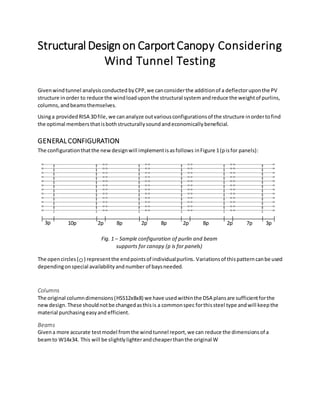
  • 1. Structural Designon CarportCanopy Considering Wind Tunnel Testing Givenwindtunnel analysisconducted byCPP,we canconsiderthe additionof a deflectoruponthe PV structure inorder to reduce the windloaduponthe structural systemandreduce the weightof purlins, columns,andbeamsthemselves. Usinga providedRISA 3Dfile,we cananalyze outvariousconfigurationsof the structure inordertofind the optimal membersthatisbothstructurallysoundandeconomicallybeneficial. GENERAL CONFIGURATION The configurationthatthe newdesignwill implementisasfollows inFigure 1(pisfor panels): The opencircles( ) representthe endpointsof individualpurlins. Variationsof thispatterncanbe used dependingonspecial availabilityandnumber of baysneeded. Columns The original columndimensions(HSS12x8x8) we have usedwithinthe DSA plansare sufficientforthe newdesign. These shouldnotbe changedasthisis a commonspec forthissteel type andwill keepthe material purchasingeasyand efficient. Beams Givena more accurate testmodel fromthe windtunnel report,we can reduce the dimensionsof a beamto W14x34. This will be slightlylighterandcheaperthanthe original W 3p 10p 2p 8p 2p 8p 2p 8p 2p 7p 3p Fig. 1 – Sample configuration of purlin and beam supports for canopy (p is for panels)
  • 2. Purlins To minimize weightandtomaximize savings,we wanttochoose cold-formedpurlinswiththinnercross- section.The model will workwithall 14gamemberpurlins(12CS4x070);however,tofurtherdecreaseto cost and weight,we canutilize a16ga memberonselectmembersof the structure.The structure does not passthe code checkif all purlinswere ata 16ga thickness. Giventhe windtunnel testmodel,we cansee thatmost of the greaterloadswill be concentratedon eitherendsof structure.Thisisindicated belowwithwindloadcase A inbothup and downdirections. We can change the leftmostandrightmostpurlinsinto a stronger14ga purlins,while the middle purlins not supportingthe critical loadscanhave a 16ga thickness. Specifically,the twoleftmostandthe two rightmostpurlinswillbe the only4purlinlineswitha14ga thickness. Fig. 2 – Side view of wind load case A Fig. 3 – Purlin set-up
  • 3. Bracing If purlinsdonot satisfythe D/Cratio, bracingscan be adjustedtoaccommodate the momentdistributed across the member. For example, one of the bracing on the top left was moved towards the middle to account fora large momentconcentratedtowardsthe middle. MEMBER SPECS Purlins Type Thickness Strength Weight 12CS4x070 14ga (0.070in) 55 ksi 5.002 lb/ft 12CS4x056 16ga (0.056in) 65 ksi 3.934 lb/ft Beams Type Thickness Strength Weight W14x37 F: 0.455 in , W: 0.285 in 50 ksi 344.028 lb/ft Columns Type Thickness Strength Weight HSS12x8x8 0.465 in 56 ksi 58.528 lb/ft SAVINGS PER BAY Each bay stretchestoabout 34.75 feetperbay.There are 12 total purlins. Cases Weightperbay Case 1: All purlins 14ga 2805.83lb Case 2: 4 purlins14ga, 8 purlins16ga 1788.93 lb Thisresultsina difference of 296.904 lbof savedforthe new purlindimensions Fig. 4 – Adjustment of bracing
  • 4. RESULTS Afterusingthe membersizesandadjustmentsfromabove,we can achieve the followingD/Cresultsfor the structure: Fig. 5 – D/C for beams and columns Fig. 6 – D/C for beams and columns