Download free for 30 days
Sign in
Upload
Language (EN)
Support
Business
Mobile
Social Media
Marketing
Technology
Art & Photos
Career
Design
Education
Presentations & Public Speaking
Government & Nonprofit
Healthcare
Internet
Law
Leadership & Management
Automotive
Engineering
Software
Recruiting & HR
Retail
Sales
Services
Science
Small Business & Entrepreneurship
Food
Environment
Economy & Finance
Data & Analytics
Investor Relations
Sports
Spiritual
News & Politics
Travel
Self Improvement
Real Estate
Entertainment & Humor
Health & Medicine
Devices & Hardware
Lifestyle
Change Language
Language
English
Español
Português
Français
Deutsche
Cancel
Save
Submit search
EN
Uploaded by
DebbieMaeTonog
PPT, PDF
13 views
Discussion on Different Rotating Machines.ppt
Discussion on the mechanism of different rotating machines
Engineering
◦
Read more
0
Save
Share
Embed
Embed presentation
Download
Download to read offline
1
/ 30
2
/ 30
3
/ 30
4
/ 30
5
/ 30
6
/ 30
7
/ 30
8
/ 30
9
/ 30
10
/ 30
11
/ 30
12
/ 30
13
/ 30
14
/ 30
15
/ 30
16
/ 30
17
/ 30
18
/ 30
19
/ 30
20
/ 30
21
/ 30
22
/ 30
23
/ 30
24
/ 30
25
/ 30
26
/ 30
27
/ 30
28
/ 30
29
/ 30
30
/ 30
More Related Content
PPT
Dcgenerator
by
sumithraLilly
PPT
Dcgenerator
by
Sumithra Ebenezer
PPT
Electric motors and generators.ppt
by
AlliverSapitula1
PPT
Electric motors and generators
by
Rakesh Pathipati
PPTX
INFORMATION ABOUT DC MACHINES AND TRANSFORMERES
by
vijayakumar653799
PPTX
Eelectrical machines 1Presenatation which covers basics of dc machines
by
Dineshkumar281116
PDF
Electrical machines 2 AC Machines
by
Velalar College of Engineering and Technology
PDF
Electrical machines iii
by
PrasadSolasa
Dcgenerator
by
sumithraLilly
Dcgenerator
by
Sumithra Ebenezer
Electric motors and generators.ppt
by
AlliverSapitula1
Electric motors and generators
by
Rakesh Pathipati
INFORMATION ABOUT DC MACHINES AND TRANSFORMERES
by
vijayakumar653799
Eelectrical machines 1Presenatation which covers basics of dc machines
by
Dineshkumar281116
Electrical machines 2 AC Machines
by
Velalar College of Engineering and Technology
Electrical machines iii
by
PrasadSolasa
Similar to Discussion on Different Rotating Machines.ppt
PPTX
DC generators and Motors construction .pptx
by
Harshal Vaidya
PPTX
last topic 10.pptx hhhaagghxnnmksaxbnbxnxjaam
by
LaLynn1
PPTX
CH 4 DC Machines.pptx
by
million22
PPTX
CH 4 DC Machines - Copy.pptx
by
million22
PPTX
induction motor
by
hamnanoor4
PPTX
generating equipments
by
Maria Romina Angustia
PPT
Chapter 11 & 12 generators & motors
by
thantar
PPT
Pertemuan 5 - Motor dan Generator Presentasi
by
AndreKurniawan49
PPTX
UNIT 2 02042024 SRaaaaaaaaaaaaaaaaaaM.pptx
by
cvkcvk1
PPT
Dc machiness
by
Deepa Rani
PPTX
G10 Science Q2-Week 9-ELECTRIC MOTORS & GENERATORS.pptx
by
IamswellynkateSerran
PPTX
UNIT 3 EEE first year full notes availab
by
abanmohammed06
PDF
Alternating Current Machines 1a
by
Talia Carbis
PPTX
GENERALIZED MACHINE THEORY Lecture One.pptx
by
BruceKwawu
PPTX
20EE237_Fundamendal of EE_MODULE II.pptx
by
SriBalaji980114
PPTX
Electrical Generators-Basicssssssss.pptx
by
awais635382
PPTX
Electrical Machine II by Jibesh Sir
by
Muntasir Mahdi
PDF
Eece 259 dc generator
by
Md. Imtiaz Pathan
PDF
Electrical Machines
by
AnirudhCR1
PPTX
SYNCHRONOUS GENERATOR.pptx
by
Zdzislaw Jan Bochynski
DC generators and Motors construction .pptx
by
Harshal Vaidya
last topic 10.pptx hhhaagghxnnmksaxbnbxnxjaam
by
LaLynn1
CH 4 DC Machines.pptx
by
million22
CH 4 DC Machines - Copy.pptx
by
million22
induction motor
by
hamnanoor4
generating equipments
by
Maria Romina Angustia
Chapter 11 & 12 generators & motors
by
thantar
Pertemuan 5 - Motor dan Generator Presentasi
by
AndreKurniawan49
UNIT 2 02042024 SRaaaaaaaaaaaaaaaaaaM.pptx
by
cvkcvk1
Dc machiness
by
Deepa Rani
G10 Science Q2-Week 9-ELECTRIC MOTORS & GENERATORS.pptx
by
IamswellynkateSerran
UNIT 3 EEE first year full notes availab
by
abanmohammed06
Alternating Current Machines 1a
by
Talia Carbis
GENERALIZED MACHINE THEORY Lecture One.pptx
by
BruceKwawu
20EE237_Fundamendal of EE_MODULE II.pptx
by
SriBalaji980114
Electrical Generators-Basicssssssss.pptx
by
awais635382
Electrical Machine II by Jibesh Sir
by
Muntasir Mahdi
Eece 259 dc generator
by
Md. Imtiaz Pathan
Electrical Machines
by
AnirudhCR1
SYNCHRONOUS GENERATOR.pptx
by
Zdzislaw Jan Bochynski
Recently uploaded
PPTX
Web Technology Overview with list of assignments along with the technology
by
YogeshDeshmukh85
PDF
22PEOIT4C Artificial Intelligence unit 3 QB Final.pdf
by
Guru Nanak Technical Institutions
PPTX
Calculation of hardness of Water on Ion Exchange.pptx
by
Chemical Engineering Dept. NIT Rourkela-769008, Odisha, India
PPTX
Ion exchange or demineralization to soften water.pptx
by
Chemical Engineering Dept. NIT Rourkela-769008, Odisha, India
PPTX
CMRP Lecture 01_Final_22.11.24 presentation
by
TamerEmam8
PDF
Introduction to Software , Product and Process
by
GunjalSanjay
PPTX
1.1 Structure of Materials_Material science.pptx
by
Dr. Sandip Thorat
PDF
22PE0IT4C_Artificial_Intelligence_Unit_1_QB_Final
by
Guru Nanak Technical Institutions
PPTX
1.2-Structure of Ceramics_ Materials Science.pptx
by
Dr. Sandip Thorat
DOCX
Hallucination Reduction In Generative Artificial Intelligence (1).docx
by
21nitinsinha
PPTX
overview of hoists in construction related to architecture
by
ptripathi2250
PDF
22PEOIT4C Artificial Intelligence Unit 2 QB Final.pdf
by
Guru Nanak Technical Institutions
PDF
Introduction : Operating-System Services
by
Sanjay Gunjal
PPTX
UNIT 1.3-Structure of Polymers_Material Science-.pptx
by
Dr. Sandip Thorat
PPTX
BANKING MANAGEMENT SYSTEM in C PROGRAM.pptx
by
mounikateegala23
PDF
TU/e - Lecture Geotechnics - Case Singelgrachtgarage-Marnix - Arkesteijn
by
Ruud Arkesteijn
PPTX
PEMET 413 KTU 2024 MODULE 2 LECTURE 3.pptx
by
VINAY B
PDF
E120A390QSR 1.2″ Round OLED Display Module 390×390 AMOLED
by
Syluxdisplay
PDF
Operating system Introduction to System Call
by
Sanjay Gunjal
PPTX
22PEOIT4C Unit 3 Session 18 First Order Logic.pptx
by
Guru Nanak Technical Institutions
Web Technology Overview with list of assignments along with the technology
by
YogeshDeshmukh85
22PEOIT4C Artificial Intelligence unit 3 QB Final.pdf
by
Guru Nanak Technical Institutions
Calculation of hardness of Water on Ion Exchange.pptx
by
Chemical Engineering Dept. NIT Rourkela-769008, Odisha, India
Ion exchange or demineralization to soften water.pptx
by
Chemical Engineering Dept. NIT Rourkela-769008, Odisha, India
CMRP Lecture 01_Final_22.11.24 presentation
by
TamerEmam8
Introduction to Software , Product and Process
by
GunjalSanjay
1.1 Structure of Materials_Material science.pptx
by
Dr. Sandip Thorat
22PE0IT4C_Artificial_Intelligence_Unit_1_QB_Final
by
Guru Nanak Technical Institutions
1.2-Structure of Ceramics_ Materials Science.pptx
by
Dr. Sandip Thorat
Hallucination Reduction In Generative Artificial Intelligence (1).docx
by
21nitinsinha
overview of hoists in construction related to architecture
by
ptripathi2250
22PEOIT4C Artificial Intelligence Unit 2 QB Final.pdf
by
Guru Nanak Technical Institutions
Introduction : Operating-System Services
by
Sanjay Gunjal
UNIT 1.3-Structure of Polymers_Material Science-.pptx
by
Dr. Sandip Thorat
BANKING MANAGEMENT SYSTEM in C PROGRAM.pptx
by
mounikateegala23
TU/e - Lecture Geotechnics - Case Singelgrachtgarage-Marnix - Arkesteijn
by
Ruud Arkesteijn
PEMET 413 KTU 2024 MODULE 2 LECTURE 3.pptx
by
VINAY B
E120A390QSR 1.2″ Round OLED Display Module 390×390 AMOLED
by
Syluxdisplay
Operating system Introduction to System Call
by
Sanjay Gunjal
22PEOIT4C Unit 3 Session 18 First Order Logic.pptx
by
Guru Nanak Technical Institutions
Discussion on Different Rotating Machines.ppt
1.
Storey: Electrical &
Electronic Systems © Pearson Education Limited 2004 OHT 23.1 Electric Motors and Generators Introduction A Simple AC Generator A Simple DC Generator DC Generators or Dynamos AC Generators or Alternators DC Motors AC Motors Universal Motors Electrical Machines – A Summary
2.
Storey: Electrical &
Electronic Systems © Pearson Education Limited 2004 OHT 23.2 Introduction In this lecture we consider various forms of rotating electrical machines These can be divided into: – generators – which convert mechanical energy into electrical energy – motors – which convert electrical energy into mechanical energy Both types operate through the interaction between a magnetic field and a set of windings
3.
Storey: Electrical &
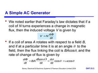
Electronic Systems © Pearson Education Limited 2004 OHT 23.3 A Simple AC Generator We noted earlier that Faraday’s law dictates that if a coil of N turns experiences a change in magnetic flux, then the induced voltage V is given by If a coil of area A rotates with respect to a field B, and if at a particular time it is at an angle to the field, then the flux linking the coil is BAcos, and the rate of change of flux is given by t Φ N V d d cos cos d d d sin d t t BA dt dΦ
4.
Storey: Electrical &
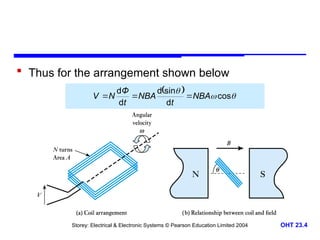
Electronic Systems © Pearson Education Limited 2004 OHT 23.4 Thus for the arrangement shown below t Φ N V d d cos d sin d d d NBA t NBA t Φ N V
5.
Storey: Electrical &
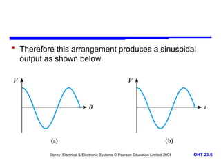
Electronic Systems © Pearson Education Limited 2004 OHT 23.5 Therefore this arrangement produces a sinusoidal output as shown below
6.
Storey: Electrical &
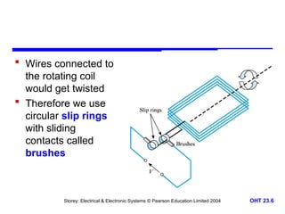
Electronic Systems © Pearson Education Limited 2004 OHT 23.6 Wires connected to the rotating coil would get twisted Therefore we use circular slip rings with sliding contacts called brushes
7.
Storey: Electrical &
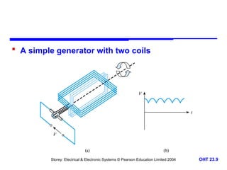
Electronic Systems © Pearson Education Limited 2004 OHT 23.7 A Simple DC Generator The alternating signal from the earlier AC generator could be converted to DC using a rectifier A more efficient approach is to replace the two slip rings with a single split slip ring called a commutator – this is arranged so that connections to the coil are reversed as the voltage from the coil changes polarity – hence the voltage across the brushes is of a single polarity – adding additional coils produces a more constant output
8.
Storey: Electrical &
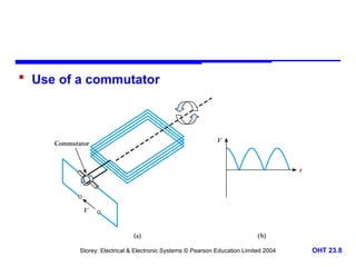
Electronic Systems © Pearson Education Limited 2004 OHT 23.8 Use of a commutator
9.
Storey: Electrical &
Electronic Systems © Pearson Education Limited 2004 OHT 23.9 A simple generator with two coils
10.
Storey: Electrical &
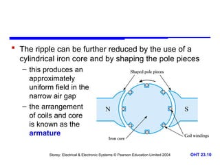
Electronic Systems © Pearson Education Limited 2004 OHT 23.10 The ripple can be further reduced by the use of a cylindrical iron core and by shaping the pole pieces – this produces an approximately uniform field in the narrow air gap – the arrangement of coils and core is known as the armature
11.
Storey: Electrical &
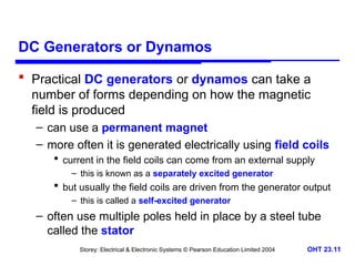
Electronic Systems © Pearson Education Limited 2004 OHT 23.11 DC Generators or Dynamos Practical DC generators or dynamos can take a number of forms depending on how the magnetic field is produced – can use a permanent magnet – more often it is generated electrically using field coils current in the field coils can come from an external supply – this is known as a separately excited generator but usually the field coils are driven from the generator output – this is called a self-excited generator – often use multiple poles held in place by a steel tube called the stator
12.
Storey: Electrical &
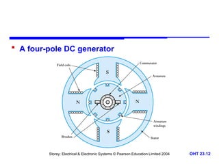
Electronic Systems © Pearson Education Limited 2004 OHT 23.12 A four-pole DC generator
13.
Storey: Electrical &
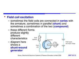
Electronic Systems © Pearson Education Limited 2004 OHT 23.13 Field coil excitation – sometimes the field coils are connected in series with the armature, sometimes in parallel (shunt) and sometimes a combination of the two (compound) – these different forms produce slightly different characteristics – diagram here shows a shunt-wound generator
14.
Storey: Electrical &
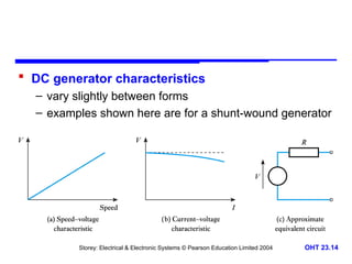
Electronic Systems © Pearson Education Limited 2004 OHT 23.14 DC generator characteristics – vary slightly between forms – examples shown here are for a shunt-wound generator
15.
Storey: Electrical &
Electronic Systems © Pearson Education Limited 2004 OHT 23.15 AC Generators or Alternators Alternators do not require commutation – this allows a simpler construction – the field coils are made to rotate while the armature windings are stationary Note: the armature windings are those that produce the output – thus the large heavy armature windings are in the stator – the lighter field coils are mounted on the rotor and direct current is fed to these by a set of slip rings
16.
Storey: Electrical &
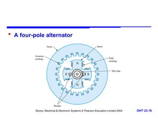
Electronic Systems © Pearson Education Limited 2004 OHT 23.16 A four-pole alternator
17.
Storey: Electrical &
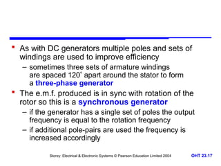
Electronic Systems © Pearson Education Limited 2004 OHT 23.17 As with DC generators multiple poles and sets of windings are used to improve efficiency – sometimes three sets of armature windings are spaced 120 apart around the stator to form a three-phase generator The e.m.f. produced is in sync with rotation of the rotor so this is a synchronous generator – if the generator has a single set of poles the output frequency is equal to the rotation frequency – if additional pole-pairs are used the frequency is increased accordingly
18.
Storey: Electrical &
Electronic Systems © Pearson Education Limited 2004 OHT 23.18 Example – see Example 23.2 from course text A four-pole alternator is required to operate at 60 Hz. What is the required rotation speed? A four-pole alternator has two pole pairs. Therefore the output frequency is twice the rotation speed. Therefore to operate at 60Hz, the required speed must be 60/2 = 30Hz. This is equivalent to 30 60 = 1800 rpm.
19.
Storey: Electrical &
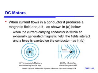
Electronic Systems © Pearson Education Limited 2004 OHT 23.19 DC Motors When current flows in a conductor it produces a magnetic field about it - as shown in (a) below – when the current-carrying conductor is within an externally generated magnetic field, the fields interact and a force is exerted on the conductor - as in (b)
20.
Storey: Electrical &
Electronic Systems © Pearson Education Limited 2004 OHT 23.20 Therefore if a conductor lies within a magnetic field: – motion of the conductor produces an electric current – an electric current in the conductor will generate motion The reciprocal nature of this relationship means that, for example, the DC generator above will function as a DC motor – although machines designed as motors are more efficient in this role Thus the four-pole DC generator shown earlier could equally well be a four-pole DC motor
21.
Storey: Electrical &
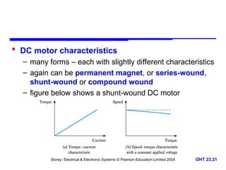
Electronic Systems © Pearson Education Limited 2004 OHT 23.21 DC motor characteristics – many forms – each with slightly different characteristics – again can be permanent magnet, or series-wound, shunt-wound or compound wound – figure below shows a shunt-wound DC motor
22.
Storey: Electrical &
Electronic Systems © Pearson Education Limited 2004 OHT 23.22 AC Motors AC motors can be divided into two main forms: – synchronous motors – induction motors High-power versions of either type invariably operate from a three-phase supply, but single-phase versions of each are also widely used – particularly in a domestic setting
23.
Storey: Electrical &
Electronic Systems © Pearson Education Limited 2004 OHT 23.23 Synchronous motors – just as a DC generator can be used as a DC motor, so AC generators (or alternators) can be used as synchronous AC motors – three phase motors use three sets of stator coils the rotating magnetic field drags the rotor around with it – single phase motors require some starting mechanism – torque is only produced when the rotor is in sync with the rotating magnetic field not self-starting – may be configured as an induction motor until its gets up to speed, then becomes a synchronous motor
24.
Storey: Electrical &
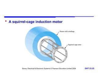
Electronic Systems © Pearson Education Limited 2004 OHT 23.24 Induction motors – these are perhaps the most important form of AC motor – rather than use slip rings to pass current to the field coils in the rotor, current is induced in the rotor by transformer action – the stator is similar to that in a synchronous motor – the rotor is simply a set of parallel conductors shorted together at either end by two conducting rings
25.
Storey: Electrical &
Electronic Systems © Pearson Education Limited 2004 OHT 23.25 A squirrel-cage induction motor
26.
Storey: Electrical &
Electronic Systems © Pearson Education Limited 2004 OHT 23.26 In a three-phase induction motor the three phases produce a rotating magnetic field (as in a three-phase synchronous motor) – a stationary conductor will see a varying magnetic field and this will induce a current – current is induced in the field coils in the same way that current is induced in the secondary of a transformer – this current turns the rotor into an electromagnet which is dragged around by the rotating magnetic field – the rotor always goes slightly slower than the magnetic field – this is the slip of the motor
27.
Storey: Electrical &
Electronic Systems © Pearson Education Limited 2004 OHT 23.27 In single-phase induction motors other techniques must be used to produce the rotating magnetic field – various techniques are used leading to various forms of motor such as capacitor motors shaded-pole motors – such motors are inexpensive and are widely used in domestic applications
28.
Storey: Electrical &
Electronic Systems © Pearson Education Limited 2004 OHT 23.28 Universal Motors While most motors operate from either AC or DC, some can operate from either These are universal motors and resemble series- wound DC motors, but are designed for both AC and DC operation – typically operate at high speed (usually > 10,000 rpm) – offer high power-to-weight ratio – ideal for portable equipment such as hand drills and vacuum cleaners
29.
Storey: Electrical &
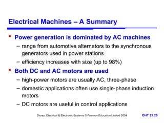
Electronic Systems © Pearson Education Limited 2004 OHT 23.29 Electrical Machines – A Summary Power generation is dominated by AC machines – range from automotive alternators to the synchronous generators used in power stations – efficiency increases with size (up to 98%) Both DC and AC motors are used – high-power motors are usually AC, three-phase – domestic applications often use single-phase induction motors – DC motors are useful in control applications
30.
Storey: Electrical &
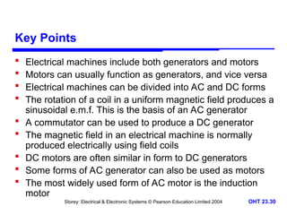
Electronic Systems © Pearson Education Limited 2004 OHT 23.30 Key Points Electrical machines include both generators and motors Motors can usually function as generators, and vice versa Electrical machines can be divided into AC and DC forms The rotation of a coil in a uniform magnetic field produces a sinusoidal e.m.f. This is the basis of an AC generator A commutator can be used to produce a DC generator The magnetic field in an electrical machine is normally produced electrically using field coils DC motors are often similar in form to DC generators Some forms of AC generator can also be used as motors The most widely used form of AC motor is the induction motor
Download