More Related Content

PPT

PPTX
Chapter 4 -Digital Transmission.pptx with free trail 
PPT

PPT

PPT

PPT
Ch3 Digital Transmission.ppt 
PPT
sffffffffffffffffffffffffffffffffffffffffffffff 
PPT
Similar to Digital transmission of the physical layer

PPT
lecture 6 ch04 digital to digital conversion 
PPT
ch4_1_v1bookbookbookbookbookbookbook.ppt 
PPT
Line_Coding.ppt for engineering students for ug and pg 
PPT
Multi level multi transition 
PPT
ch04-digital-transmission.ppt 
PPT
ch4_1_v1.pptwwwwwwwwwwwwwwwwwwwwwwwwwwwwwww 
PPT

PPT

PPT
Chapter 4 digital transmission computer_network 
PPT

PPT

PPT
Chapter 4 - Digital Transmission 
PPT
Encoding and Modulating Data Signal from analog to digital and from digital t... 
PPT

PPT

PPT

PPT
Data Communication and Networking 
PPT
ch4_1_v1edit-1.ppt digital transmission from pl 
PPT
ch4_1_v1edit-1.pptjjjjjjjjjjjjjjjjjjjjjjjjjjjjjjkkkkkkkkkkkkkkkkkk 
PDF
Computer Networks/Computer Engineering.pdf Recently uploaded

PDF
IPEC Presentation - Partial discharge Pro .pdf 
PPTX
MECCA Empire – Hotel Shuttle System for the 2026 FIFA World Cup 
PDF
Handheld_Laser_Welding_Presentation 2.pdf 
PPTX
firewall Selection in production life pptx 
PPTX
Power point presentation on introduction of software engineering 
PPTX
Network Security v1.0 - Module 2.pptx 
PPTX
ISO 14224 Compliance & CMMS Software — A Comprehensive Guide for Reliable Mai... 
PPTX
علي نفط.pptx هندسة النفط هندسة النفط والغاز 
PPTX
Natural Gas fundamentals and GRU for associated gas trap.pptx 
PPTX
Data Science with R Final yrUnit II.pptx 
PDF
Basic Engineering mechanical handwriting notes 
PPTX
Revolutionizing Facilities Management with MaintWiz — AI CMMS for Smart FMaaS 
PPTX
Plant Performance Strategies: Enhanced Reliability & Operational Efficiency w... 
PPTX
The Importance of Maintenance Budgets — Maximize Reliability & Control Costs ... 
PDF
AI-Driven CTI for Business: Emerging Threats, Attack Strategies, and Defensiv... 
PPTX
Track & Monitor Preventive Maintenance — Best Practices with MaintWiz CMMS 
PPTX
Preventive Maintenance Program for Compressors – Complete Guide 
PDF
Human computer Interface ppt aUNIT 3.pdf 
PDF
Best Architecture in Kovilpatti - Amar Dexign Scape.pdf 
PPTX
Role of In Vitro and In Vivo Testing biomedical engineering Digital transmission of the physical layer
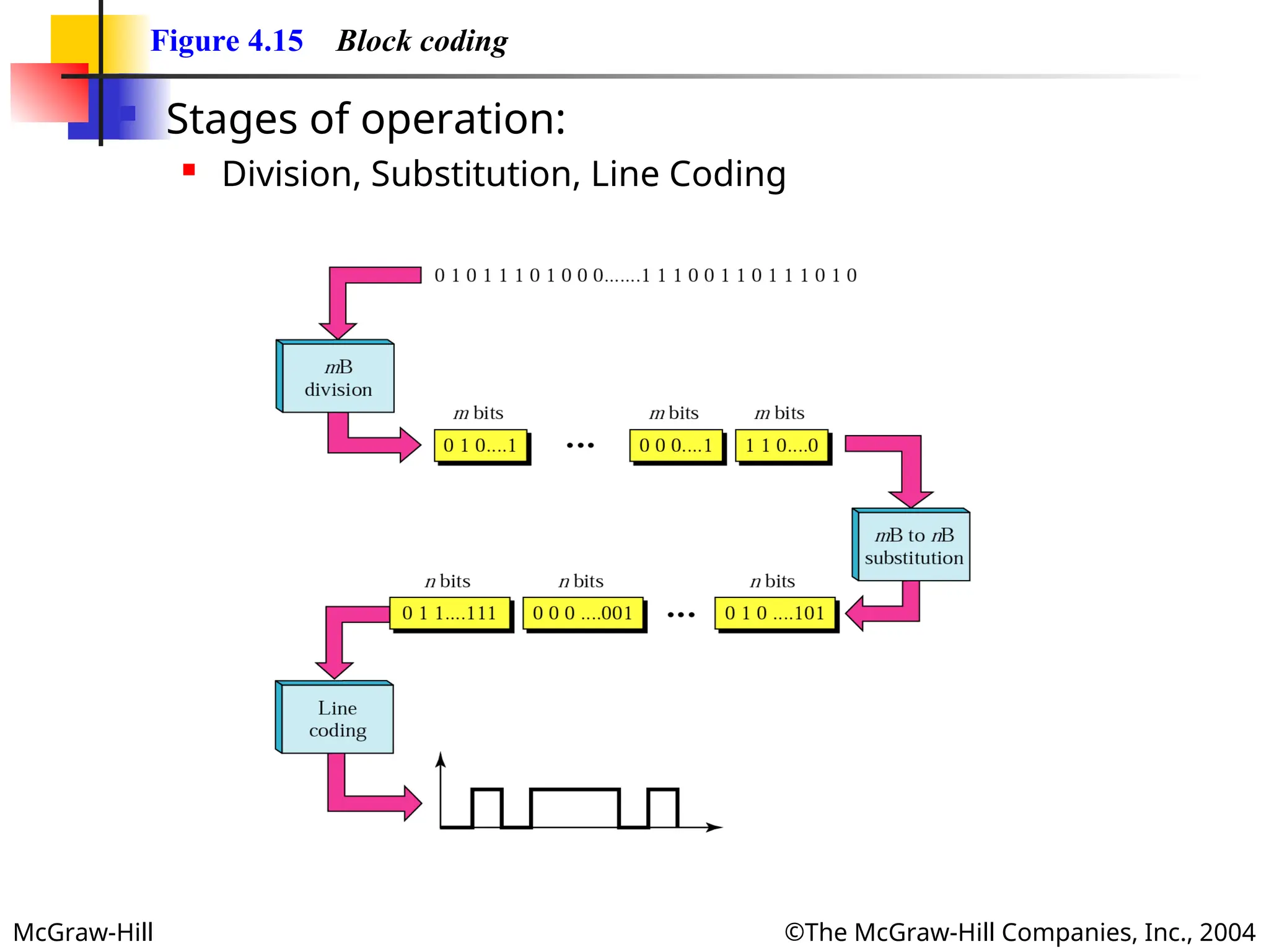
- 1.
- 2.
McGraw-Hill ©The McGraw-HillCompanies, Inc., 2004
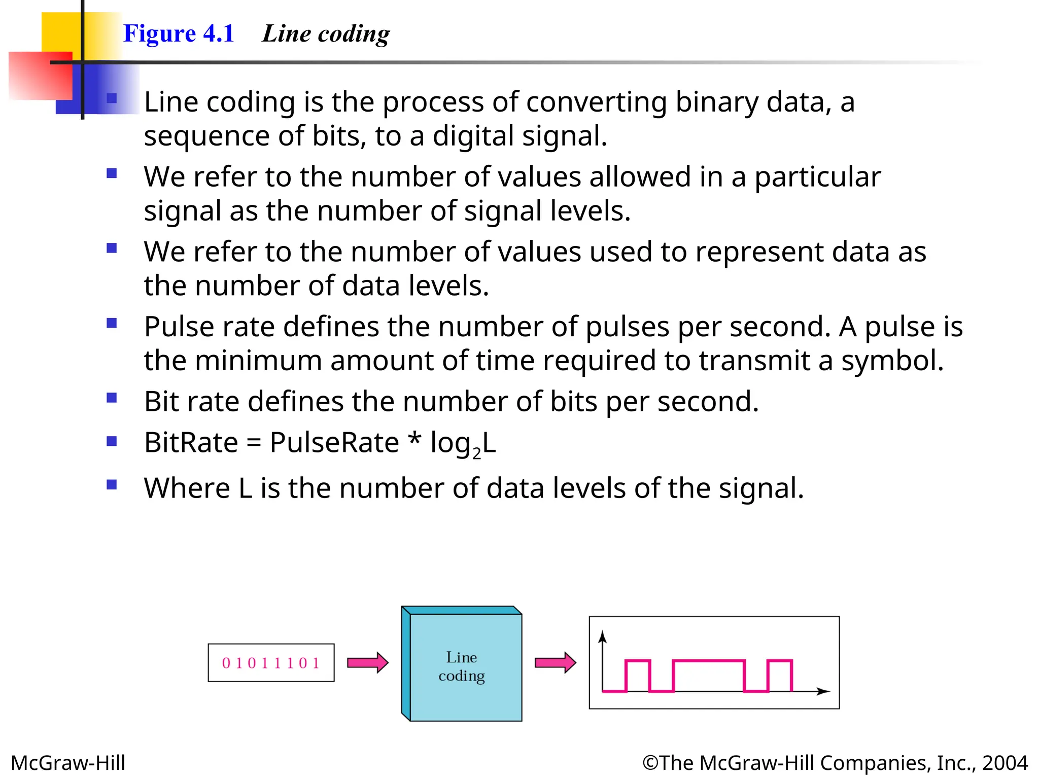
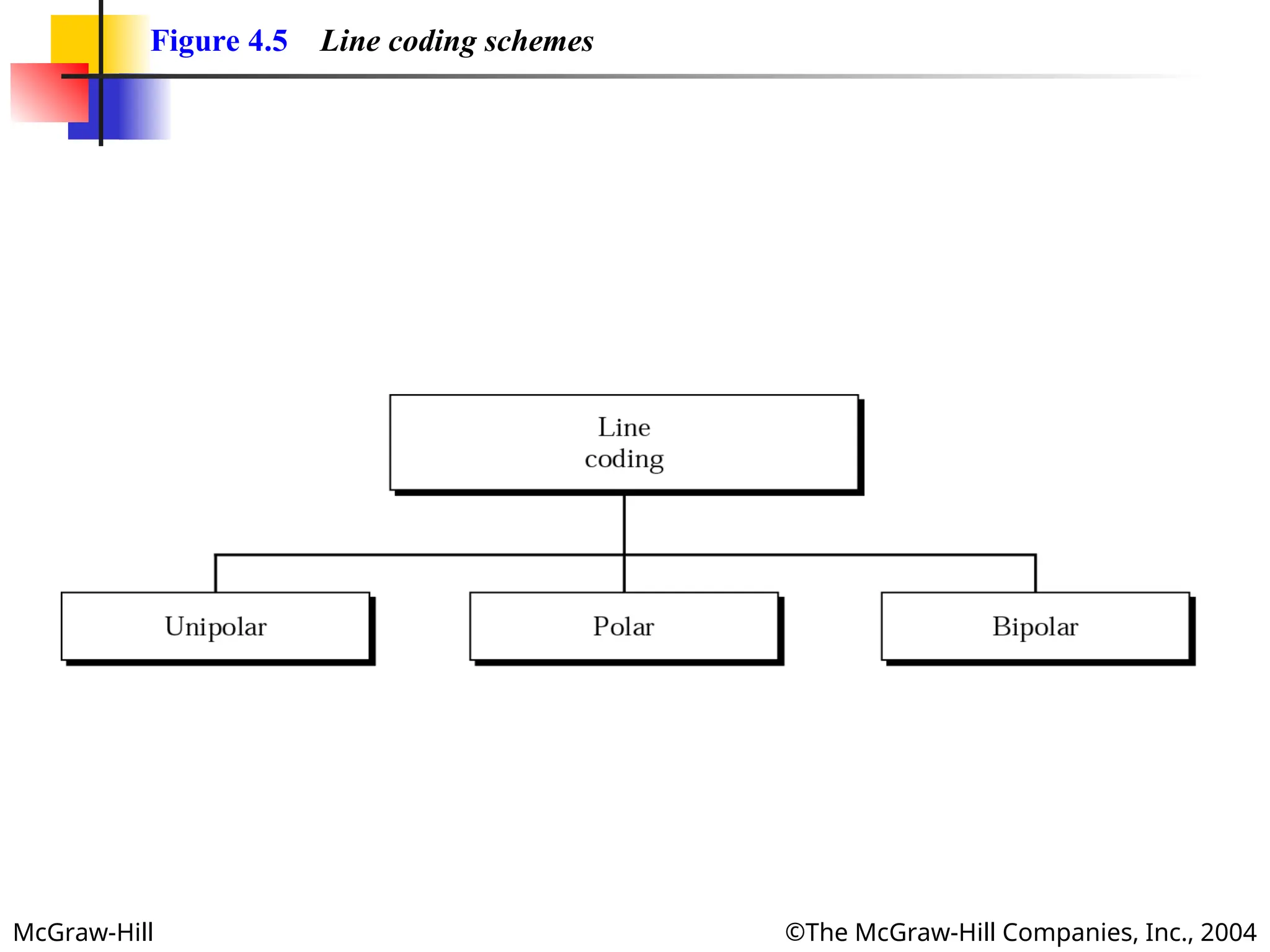
Figure 4.1 Line coding
Line coding is the process of converting binary data, a
sequence of bits, to a digital signal.
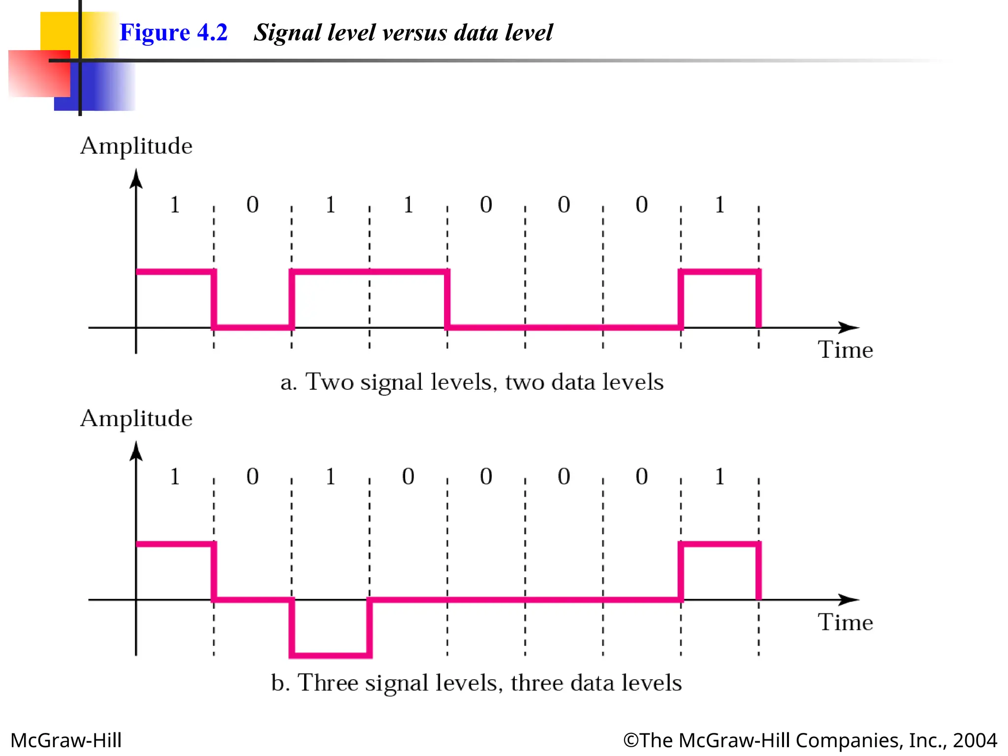
We refer to the number of values allowed in a particular
signal as the number of signal levels.
We refer to the number of values used to represent data as
the number of data levels.
Pulse rate defines the number of pulses per second. A pulse is
the minimum amount of time required to transmit a symbol.
Bit rate defines the number of bits per second.
BitRate = PulseRate * log2L
Where L is the number of data levels of the signal.
- 3.
- 4.
McGraw-Hill ©The McGraw-HillCompanies, Inc., 2004
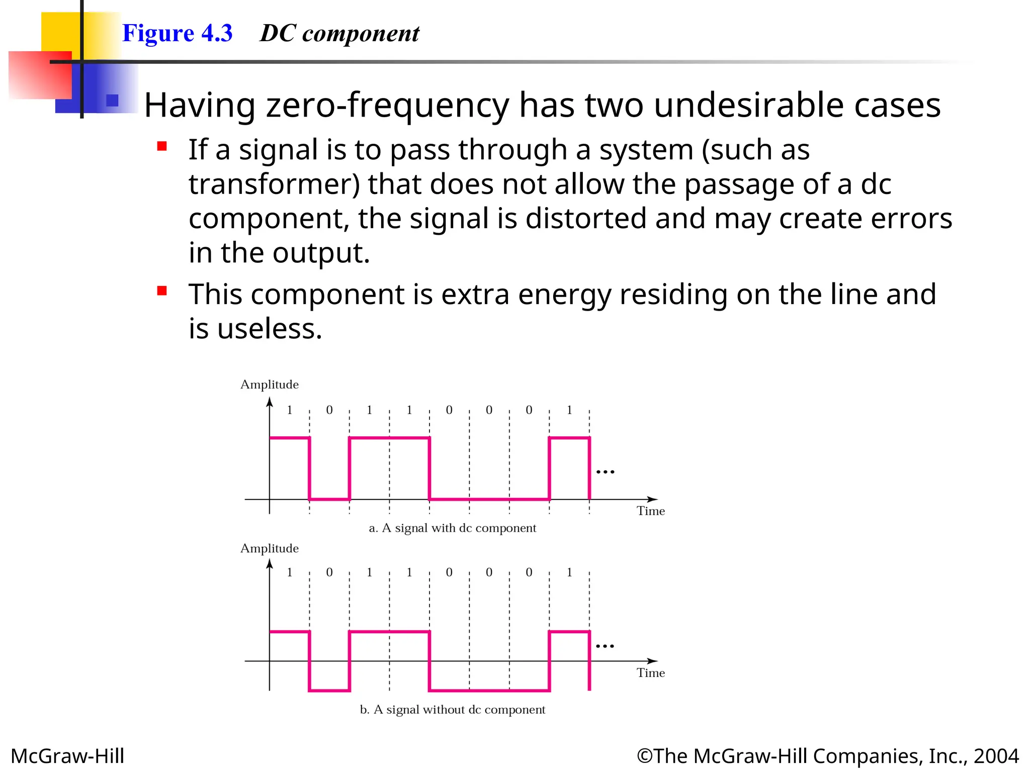
Figure 4.3 DC component
Having zero-frequency has two undesirable cases
If a signal is to pass through a system (such as
transformer) that does not allow the passage of a dc
component, the signal is distorted and may create errors
in the output.
This component is extra energy residing on the line and
is useless.
- 5.
McGraw-Hill ©The McGraw-HillCompanies, Inc., 2004
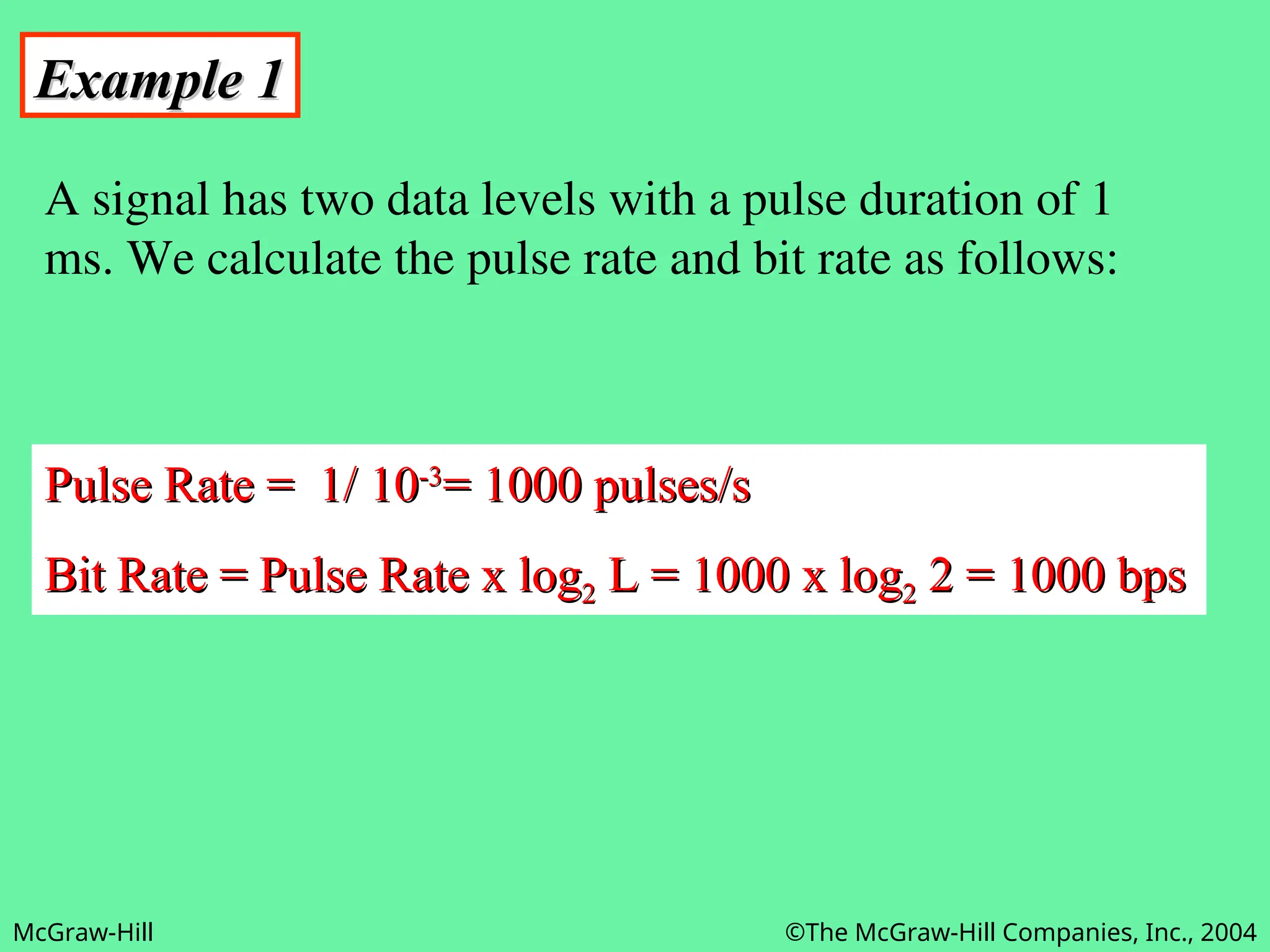
Example 1
Example 1
A signal has two data levels with a pulse duration of 1
ms. We calculate the pulse rate and bit rate as follows:
Pulse Rate = 1/ 10
Pulse Rate = 1/ 10-3
-3
= 1000 pulses/s
= 1000 pulses/s
Bit Rate = Pulse Rate x log
Bit Rate = Pulse Rate x log2
2 L = 1000 x log
L = 1000 x log2
2 2 = 1000 bps
2 = 1000 bps
- 6.
McGraw-Hill ©The McGraw-HillCompanies, Inc., 2004
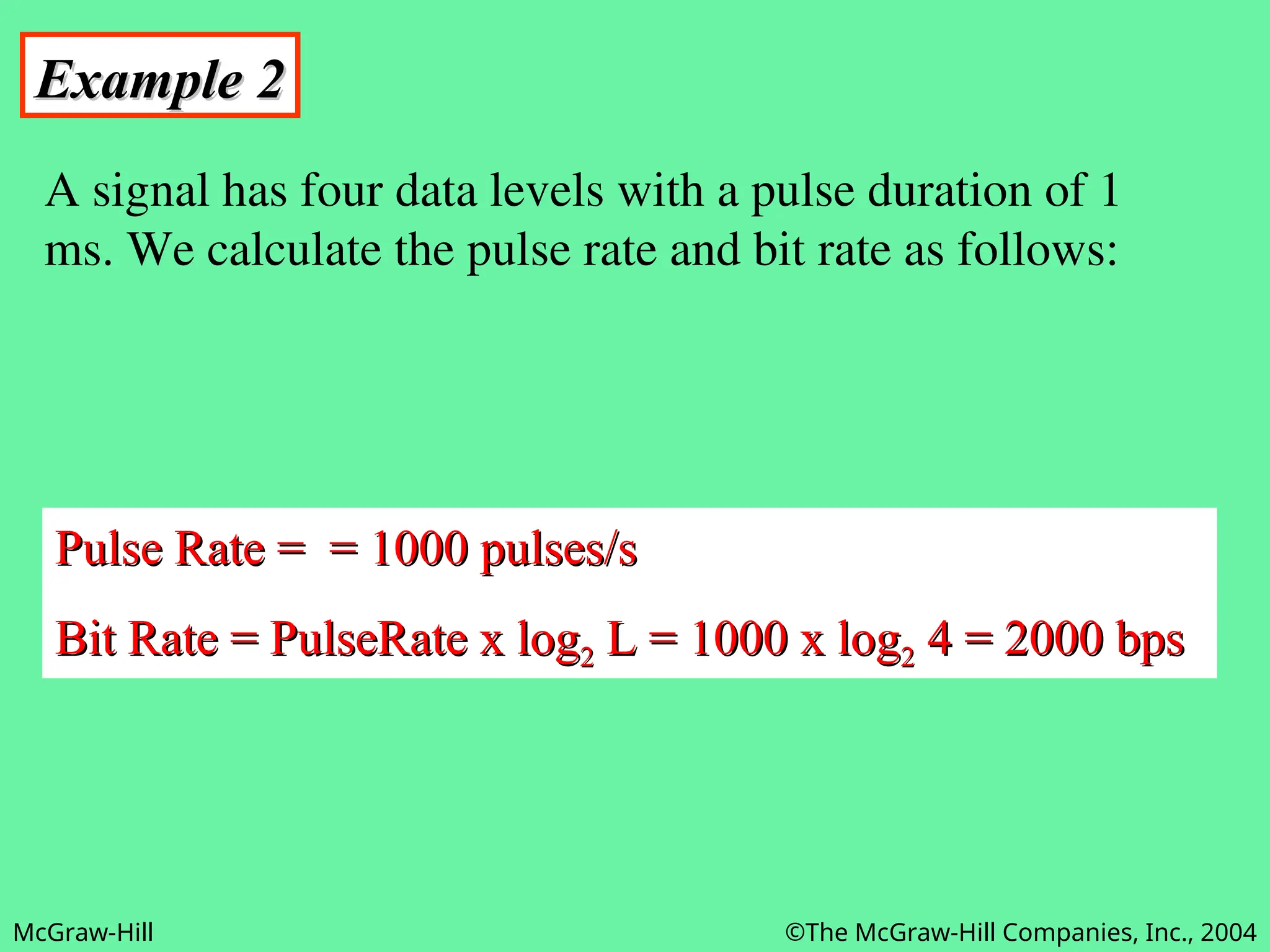
Example 2
Example 2
A signal has four data levels with a pulse duration of 1
ms. We calculate the pulse rate and bit rate as follows:
Pulse Rate = = 1000 pulses/s
Pulse Rate = = 1000 pulses/s
Bit Rate = PulseRate x log
Bit Rate = PulseRate x log2
2 L = 1000 x log
L = 1000 x log2
2 4 = 2000 bps
4 = 2000 bps
- 7.
McGraw-Hill ©The McGraw-HillCompanies, Inc., 2004
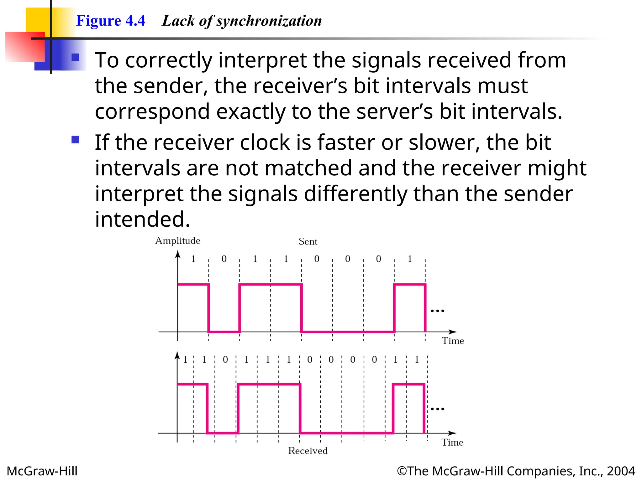
Figure 4.4 Lack of synchronization
To correctly interpret the signals received from
the sender, the receiver’s bit intervals must
correspond exactly to the server’s bit intervals.
If the receiver clock is faster or slower, the bit
intervals are not matched and the receiver might
interpret the signals differently than the sender
intended.
- 8.
McGraw-Hill ©The McGraw-HillCompanies, Inc., 2004
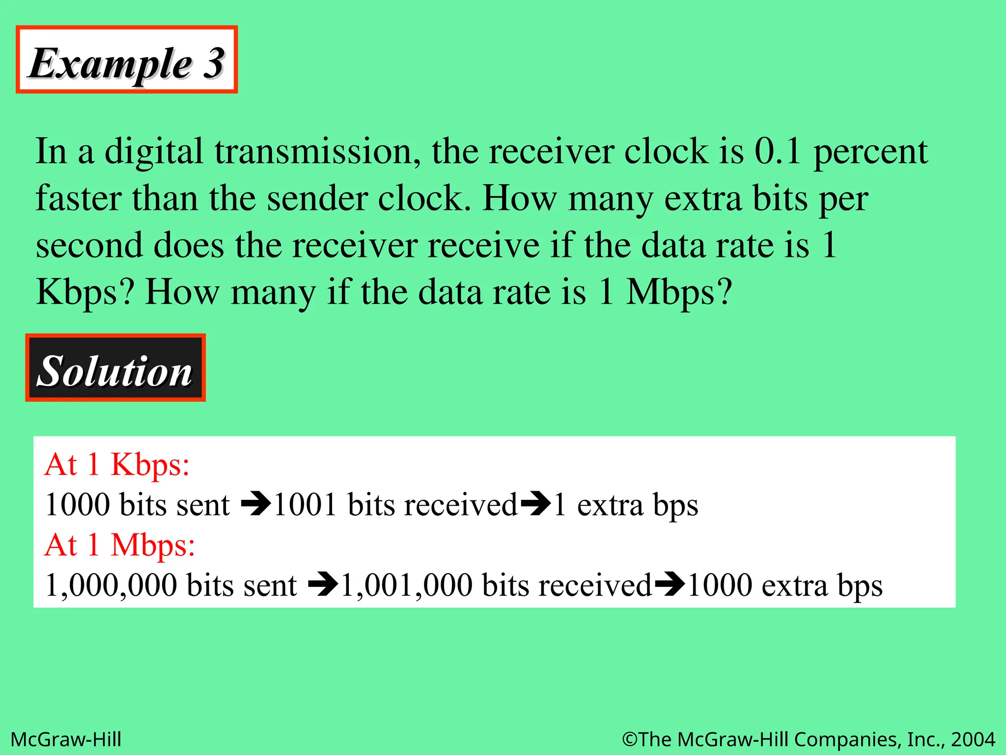
Example 3
Example 3
In a digital transmission, the receiver clock is 0.1 percent
faster than the sender clock. How many extra bits per
second does the receiver receive if the data rate is 1
Kbps? How many if the data rate is 1 Mbps?
Solution
Solution
At 1 Kbps:
1000 bits sent 1001 bits received1 extra bps
At 1 Mbps:
1,000,000 bits sent 1,001,000 bits received1000 extra bps
- 9.
- 10.
McGraw-Hill ©The McGraw-HillCompanies, Inc., 2004
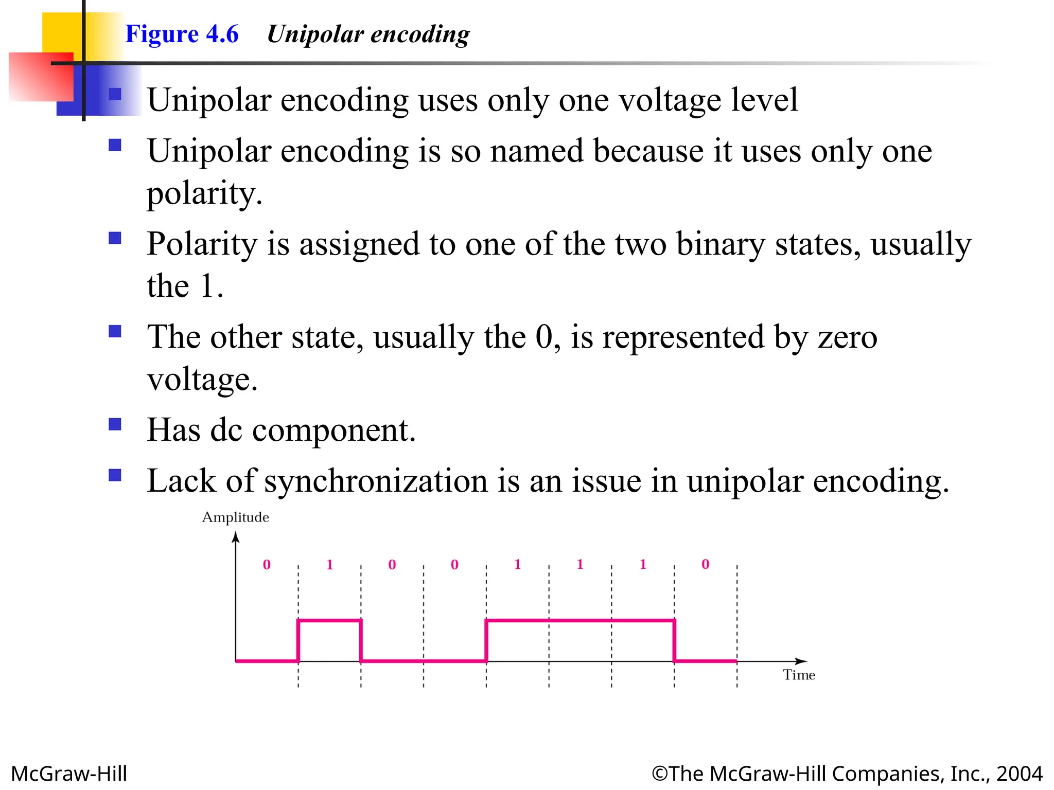
Figure 4.6 Unipolar encoding
Unipolar encoding uses only one voltage level
Unipolar encoding is so named because it uses only one
polarity.
Polarity is assigned to one of the two binary states, usually
the 1.
The other state, usually the 0, is represented by zero
voltage.
Has dc component.
Lack of synchronization is an issue in unipolar encoding.
- 11.
McGraw-Hill ©The McGraw-HillCompanies, Inc., 2004
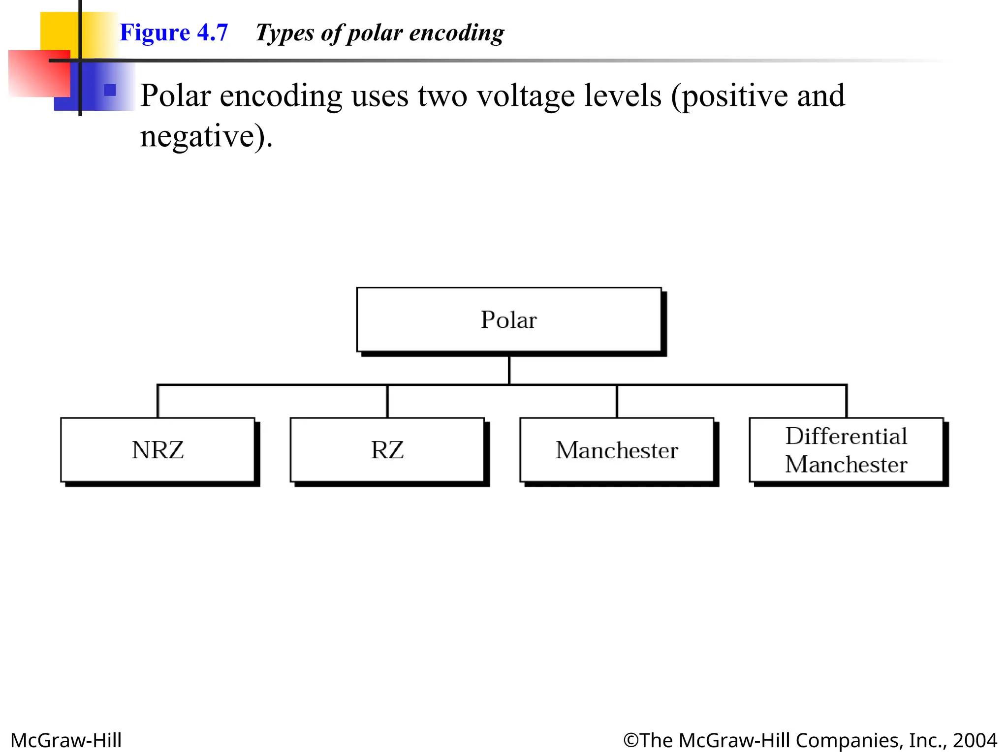
Figure 4.7 Types of polar encoding
Polar encoding uses two voltage levels (positive and
negative).
- 12.
McGraw-Hill ©The McGraw-HillCompanies, Inc., 2004
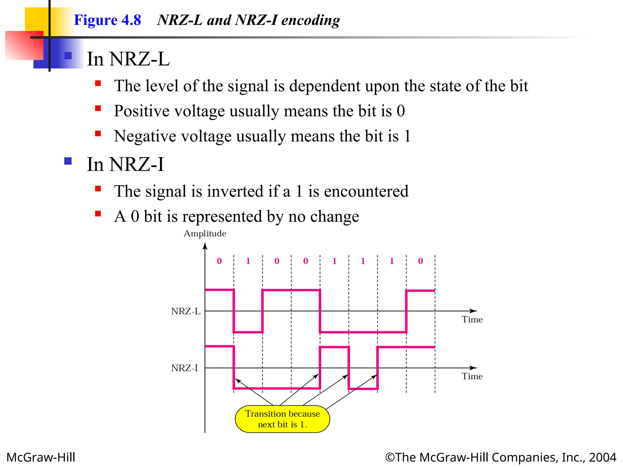
Figure 4.8 NRZ-L and NRZ-I encoding
In NRZ-L
The level of the signal is dependent upon the state of the bit
Positive voltage usually means the bit is 0
Negative voltage usually means the bit is 1
In NRZ-I
The signal is inverted if a 1 is encountered
A 0 bit is represented by no change
- 13.
McGraw-Hill ©The McGraw-HillCompanies, Inc., 2004
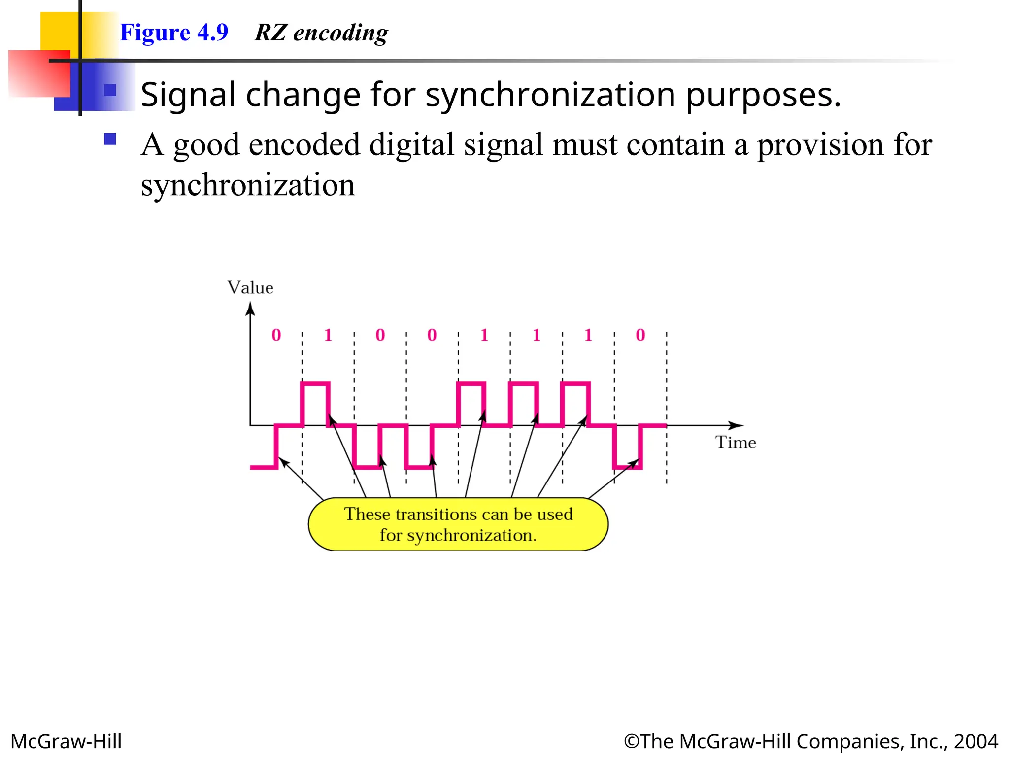
Figure 4.9 RZ encoding
Signal change for synchronization purposes.
A good encoded digital signal must contain a provision for
synchronization
- 14.
McGraw-Hill ©The McGraw-HillCompanies, Inc., 2004
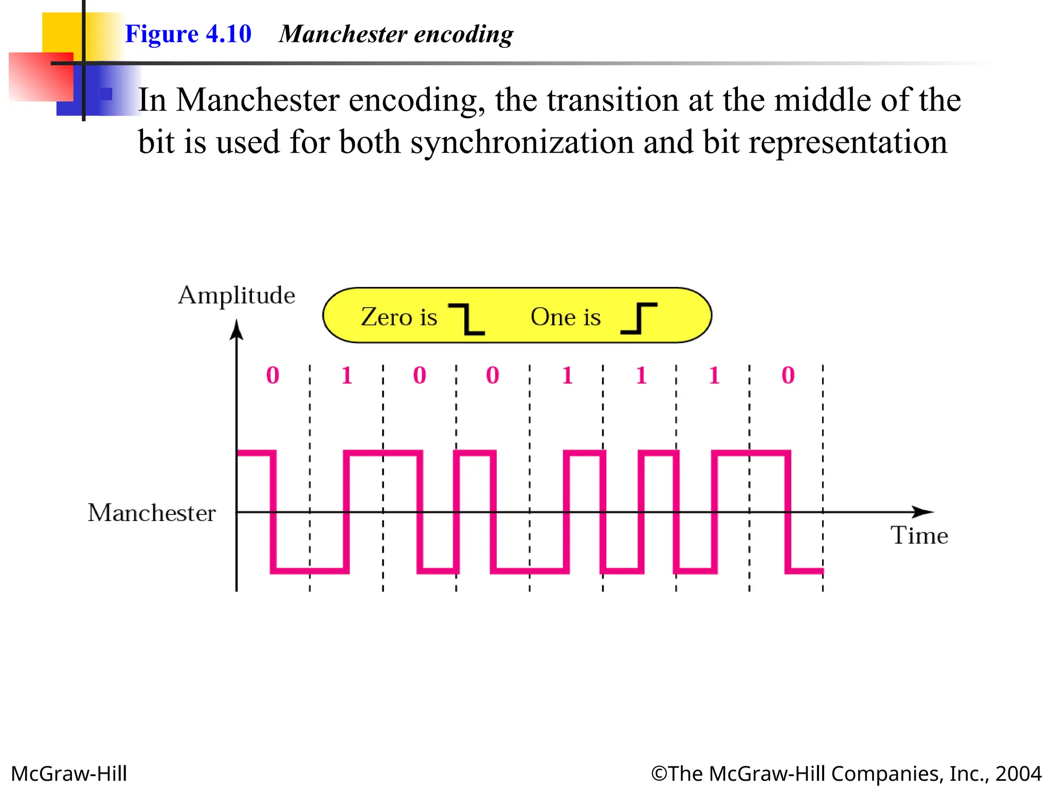
Figure 4.10 Manchester encoding
In Manchester encoding, the transition at the middle of the
bit is used for both synchronization and bit representation
- 15.
McGraw-Hill ©The McGraw-HillCompanies, Inc., 2004
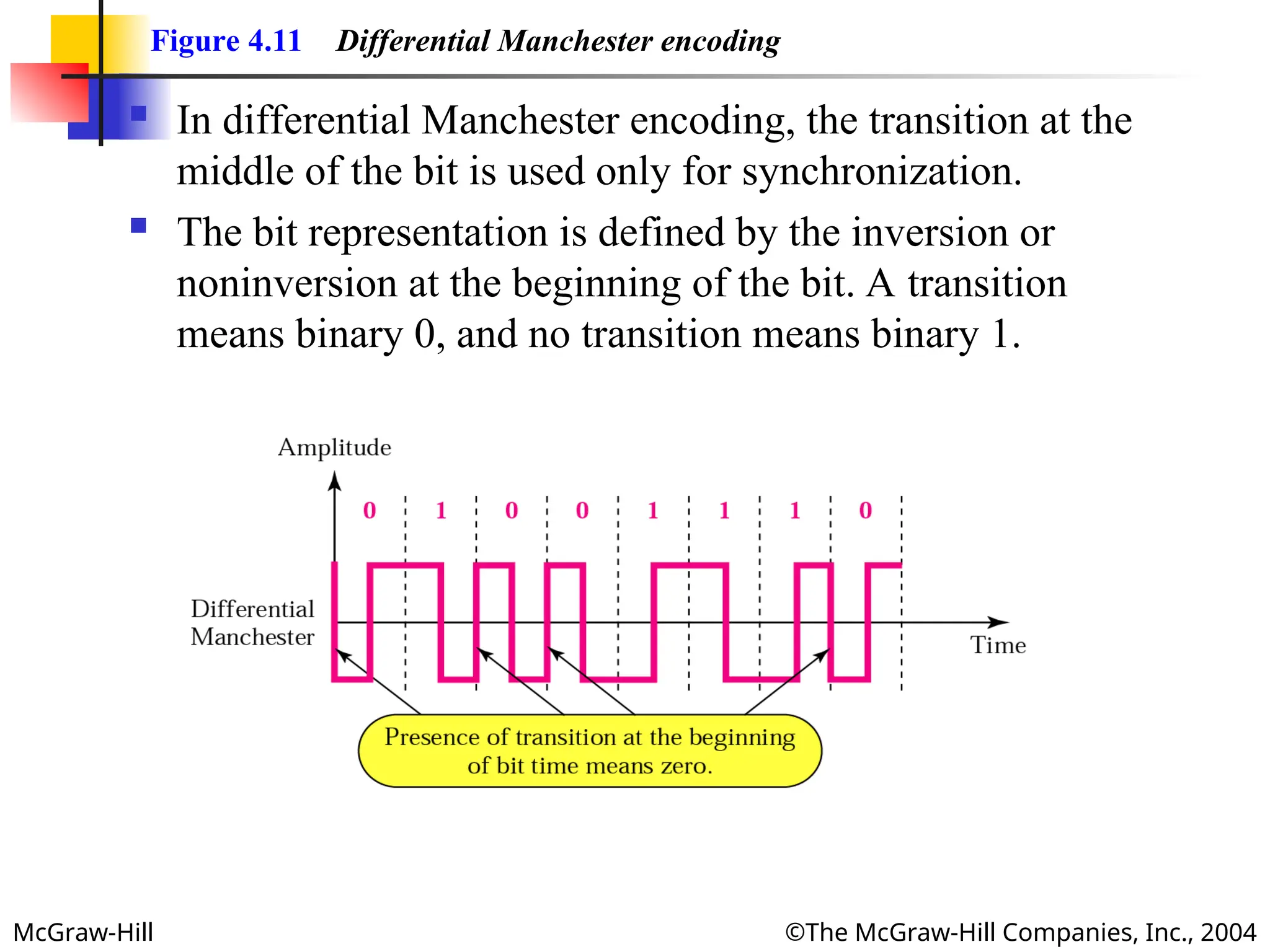
Figure 4.11 Differential Manchester encoding
In differential Manchester encoding, the transition at the
middle of the bit is used only for synchronization.
The bit representation is defined by the inversion or
noninversion at the beginning of the bit. A transition
means binary 0, and no transition means binary 1.
- 16.
McGraw-Hill ©The McGraw-HillCompanies, Inc., 2004
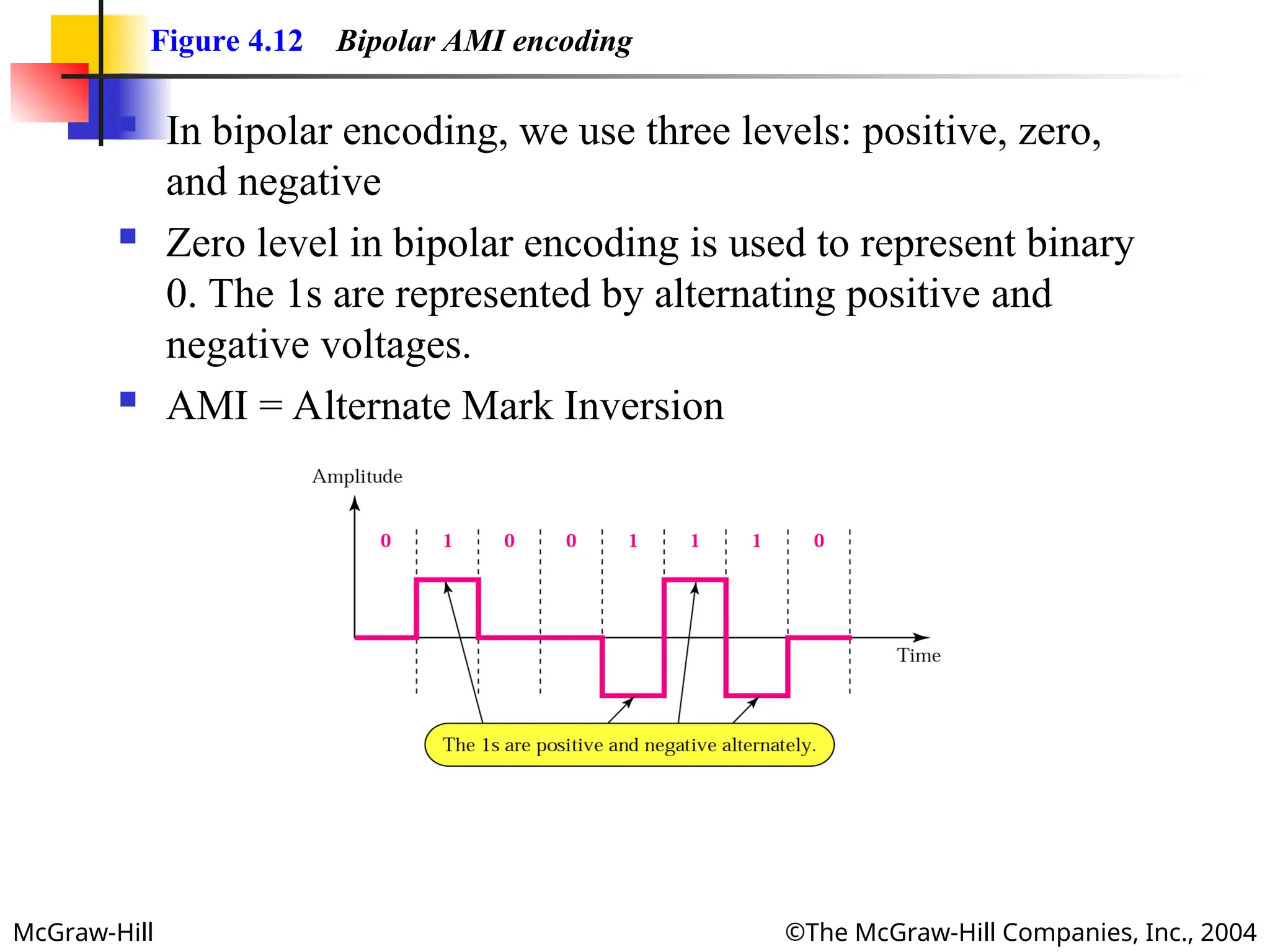
Figure 4.12 Bipolar AMI encoding
In bipolar encoding, we use three levels: positive, zero,
and negative
Zero level in bipolar encoding is used to represent binary
0. The 1s are represented by alternating positive and
negative voltages.
AMI = Alternate Mark Inversion
- 17.
- 18.
- 19.
McGraw-Hill ©The McGraw-HillCompanies, Inc., 2004
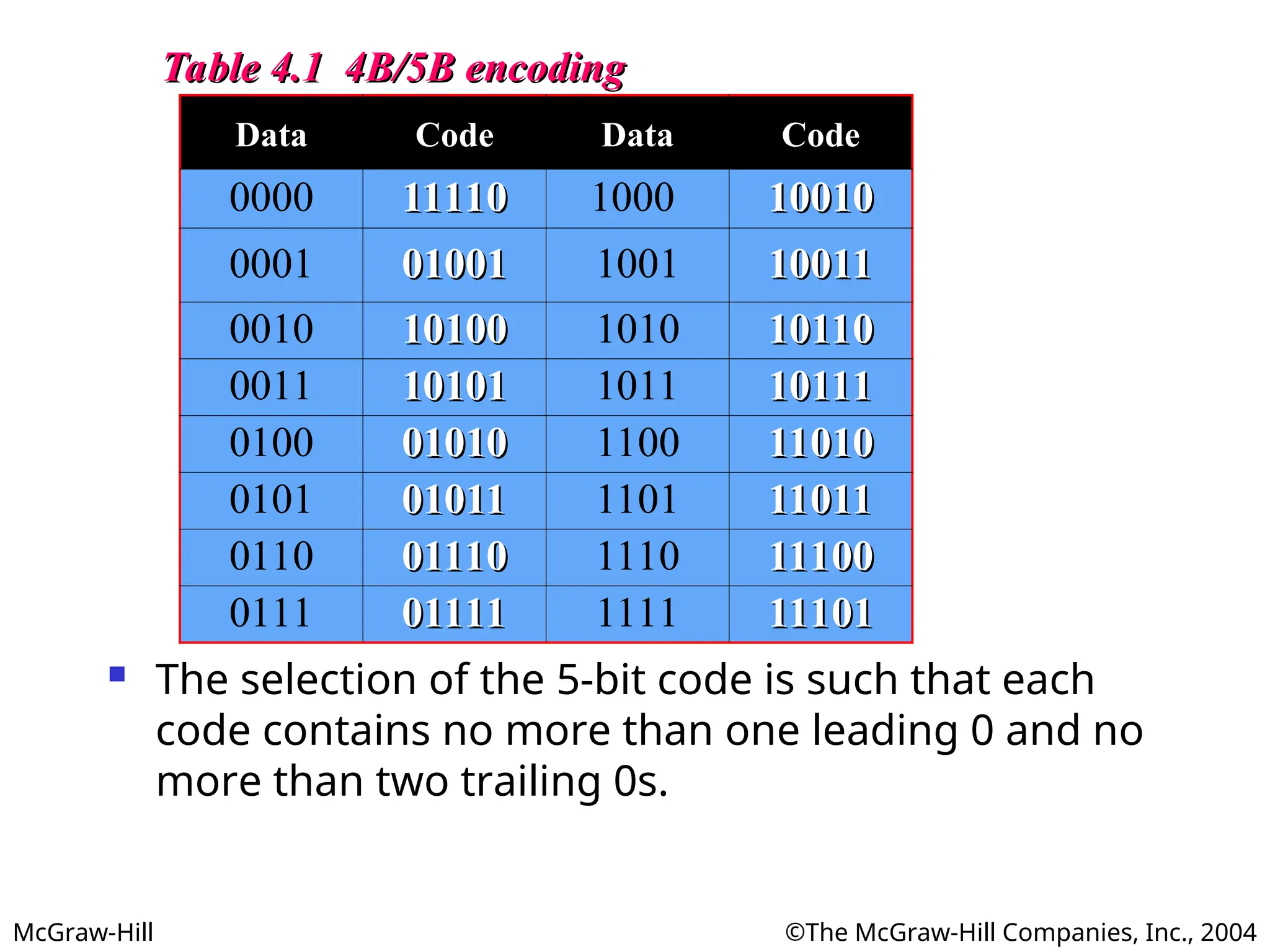
Table 4.1 4B/5B encoding
Table 4.1 4B/5B encoding
Data Code Data Code
0000 11110
11110 1000 10010
10010
0001 01001
01001 1001 10011
10011
0010 10100
10100 1010 10110
10110
0011 10101
10101 1011 10111
10111
0100 01010
01010 1100 11010
11010
0101 01011
01011 1101 11011
11011
0110 01110
01110 1110 11100
11100
0111 01111
01111 1111 11101
11101
The selection of the 5-bit code is such that each
code contains no more than one leading 0 and no
more than two trailing 0s.
- 20.
McGraw-Hill ©The McGraw-HillCompanies, Inc., 2004
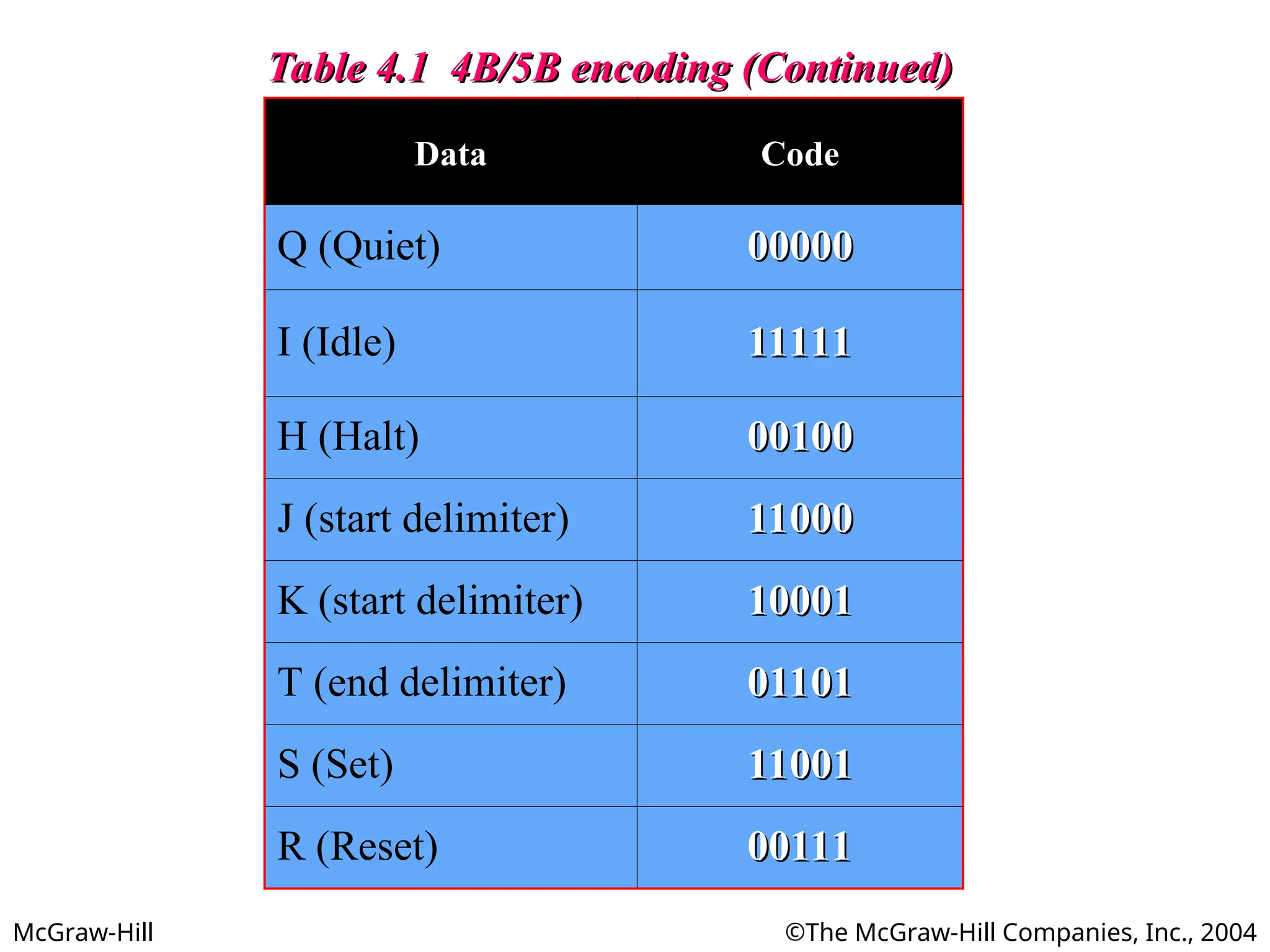
Table 4.1 4B/5B encoding (Continued)
Table 4.1 4B/5B encoding (Continued)
Data Code
Q (Quiet) 00000
00000
I (Idle) 11111
11111
H (Halt) 00100
00100
J (start delimiter) 11000
11000
K (start delimiter) 10001
10001
T (end delimiter) 01101
01101
S (Set) 11001
11001
R (Reset) 00111
00111
- 21.
McGraw-Hill ©The McGraw-HillCompanies, Inc., 2004
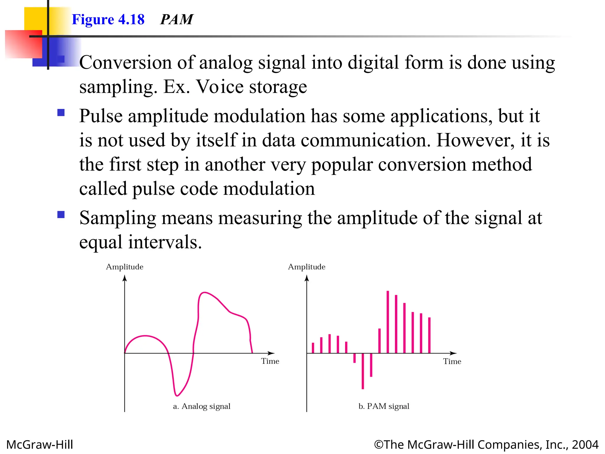
Figure 4.18 PAM
Conversion of analog signal into digital form is done using
sampling. Ex. Voice storage
Pulse amplitude modulation has some applications, but it
is not used by itself in data communication. However, it is
the first step in another very popular conversion method
called pulse code modulation
Sampling means measuring the amplitude of the signal at
equal intervals.
- 22.
McGraw-Hill ©The McGraw-HillCompanies, Inc., 2004
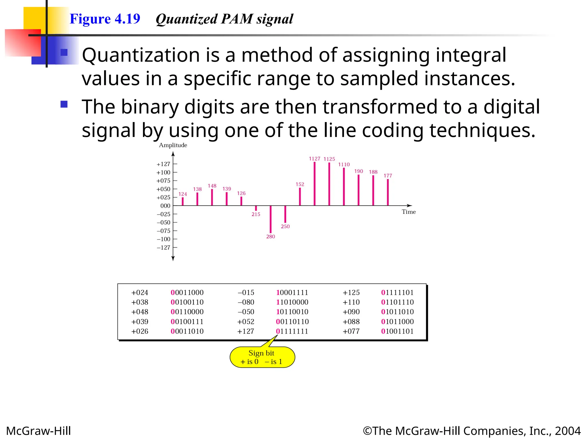
Figure 4.19 Quantized PAM signal
Quantization is a method of assigning integral
values in a specific range to sampled instances.
The binary digits are then transformed to a digital
signal by using one of the line coding techniques.
- 23.
- 24.
McGraw-Hill ©The McGraw-HillCompanies, Inc., 2004
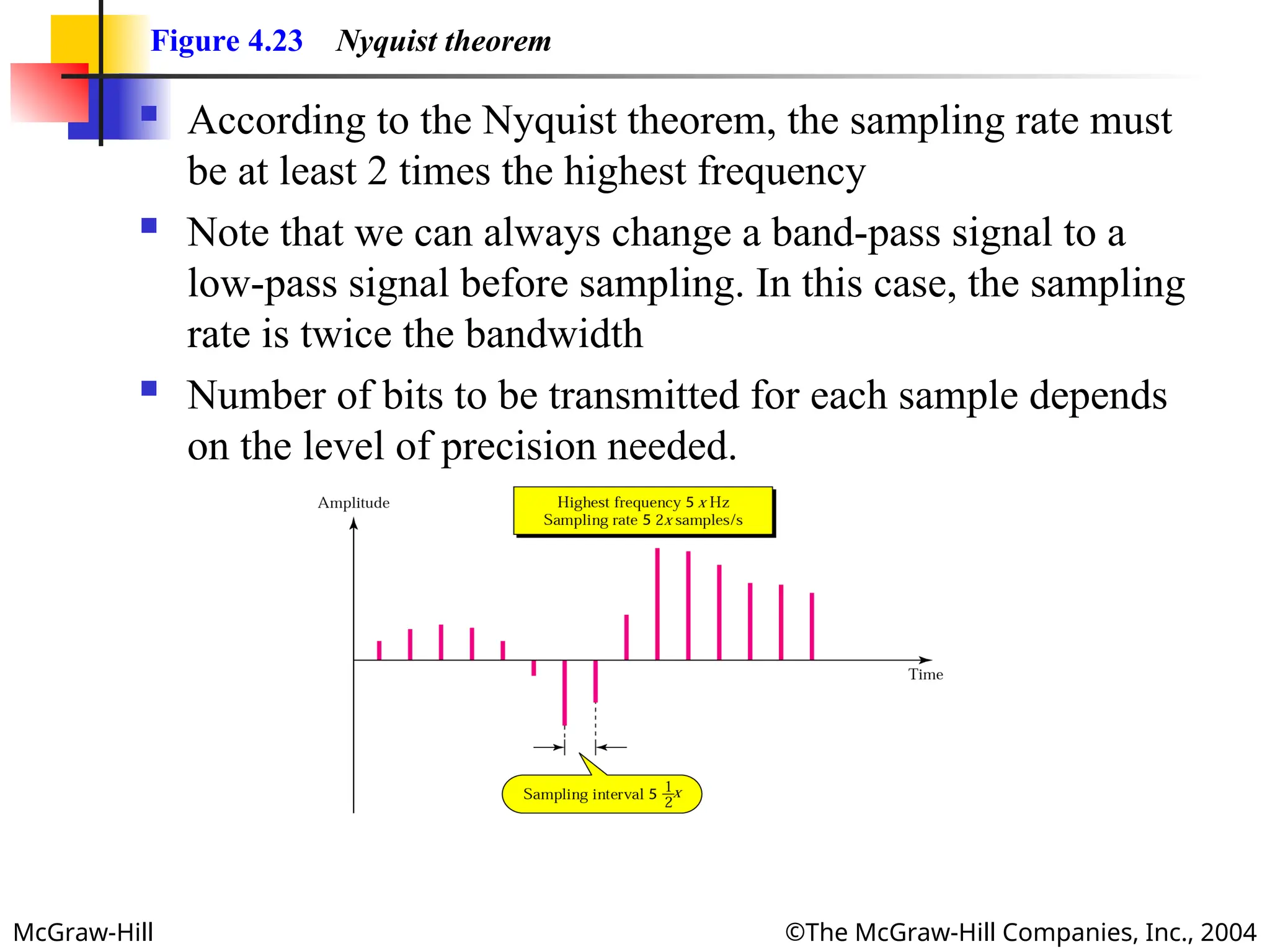
Figure 4.23 Nyquist theorem
According to the Nyquist theorem, the sampling rate must
be at least 2 times the highest frequency
Note that we can always change a band-pass signal to a
low-pass signal before sampling. In this case, the sampling
rate is twice the bandwidth
Number of bits to be transmitted for each sample depends
on the level of precision needed.
- 25.
McGraw-Hill ©The McGraw-HillCompanies, Inc., 2004
Example 4
Example 4
What sampling rate is needed for a signal with a
bandwidth of 10,000 Hz (1000 to 11,000 Hz)?
Solution
Solution
The sampling rate must be twice the highest frequency in
the signal:
Sampling rate = 2 x (11,000) = 22,000 samples/s
Sampling rate = 2 x (11,000) = 22,000 samples/s
- 26.
McGraw-Hill ©The McGraw-HillCompanies, Inc., 2004
Example 5
Example 5
A signal is sampled. Each sample requires at least 12
levels of precision (+0 to +5 and -0 to -5). How many bits
should be sent for each sample?
Solution
Solution
We need 4 bits; 1 bit for the sign and 3 bits for the value.
A 3-bit value can represent 23
= 8 levels (000 to 111),
which is more than what we need. A 2-bit value is not
enough since 22
= 4. A 4-bit value is too much because 24
= 16.
- 27.
McGraw-Hill ©The McGraw-HillCompanies, Inc., 2004
Example 6
Example 6
We want to digitize the human voice. What is the bit rate,
assuming 8 bits per sample?
Solution
Solution
The human voice normally contains frequencies from 0
to 4000 Hz.
Sampling rate = 4000 x 2 = 8000 samples/s
Sampling rate = 4000 x 2 = 8000 samples/s
Bit rate = sampling rate x number of bits per sample
Bit rate = sampling rate x number of bits per sample
= 8000 x 8 = 64,000 bps = 64 Kbps
= 8000 x 8 = 64,000 bps = 64 Kbps
- 28.
McGraw-Hill ©The McGraw-HillCompanies, Inc., 2004
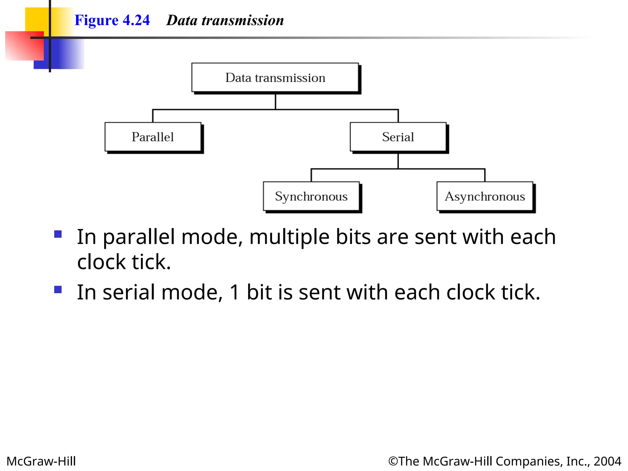
Figure 4.24 Data transmission
In parallel mode, multiple bits are sent with each
clock tick.
In serial mode, 1 bit is sent with each clock tick.
- 29.
McGraw-Hill ©The McGraw-HillCompanies, Inc., 2004
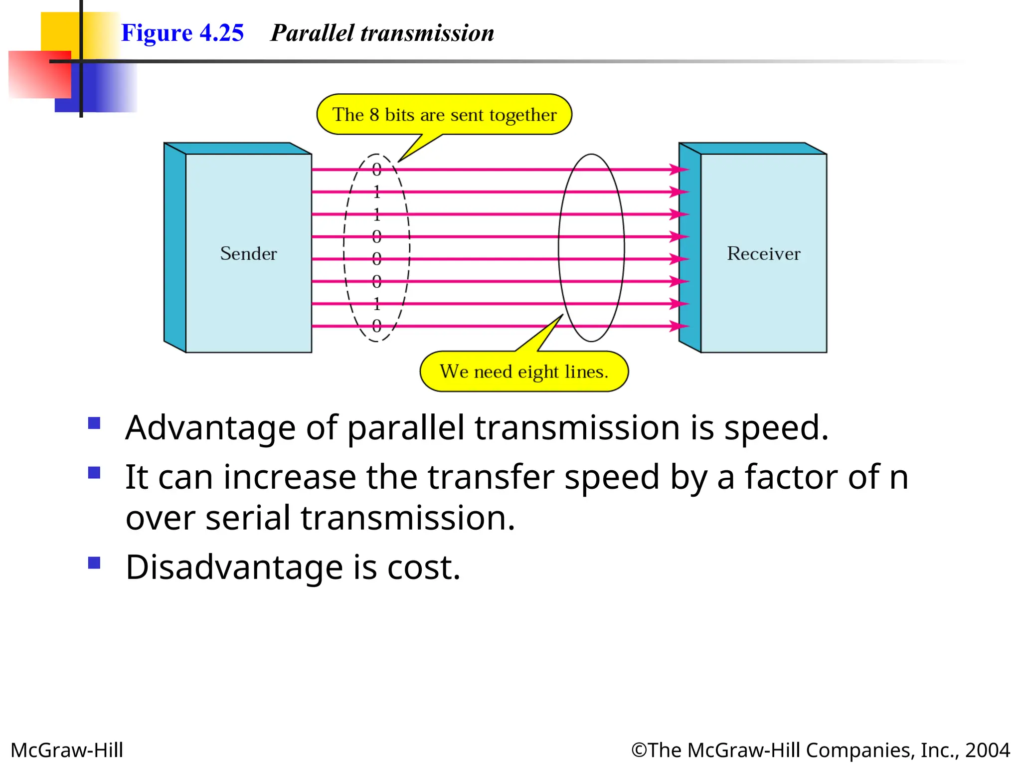
Figure 4.25 Parallel transmission
Advantage of parallel transmission is speed.
It can increase the transfer speed by a factor of n
over serial transmission.
Disadvantage is cost.
- 30.
McGraw-Hill ©The McGraw-HillCompanies, Inc., 2004
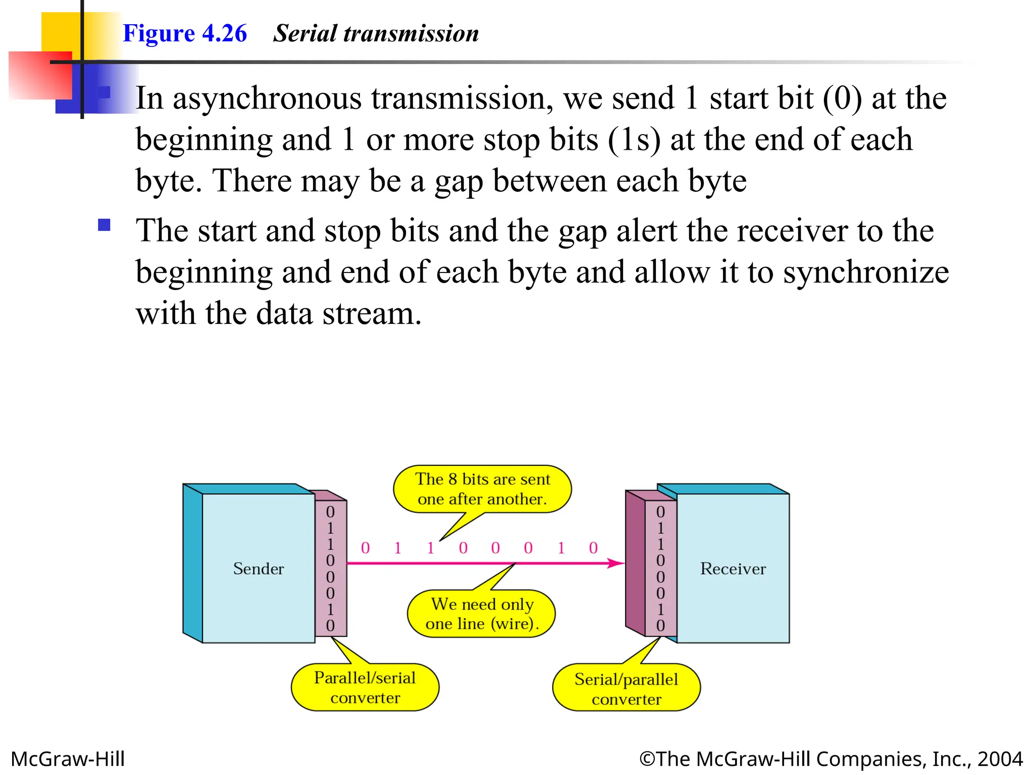
Figure 4.26 Serial transmission
In asynchronous transmission, we send 1 start bit (0) at the
beginning and 1 or more stop bits (1s) at the end of each
byte. There may be a gap between each byte
The start and stop bits and the gap alert the receiver to the
beginning and end of each byte and allow it to synchronize
with the data stream.
- 31.
McGraw-Hill ©The McGraw-HillCompanies, Inc., 2004
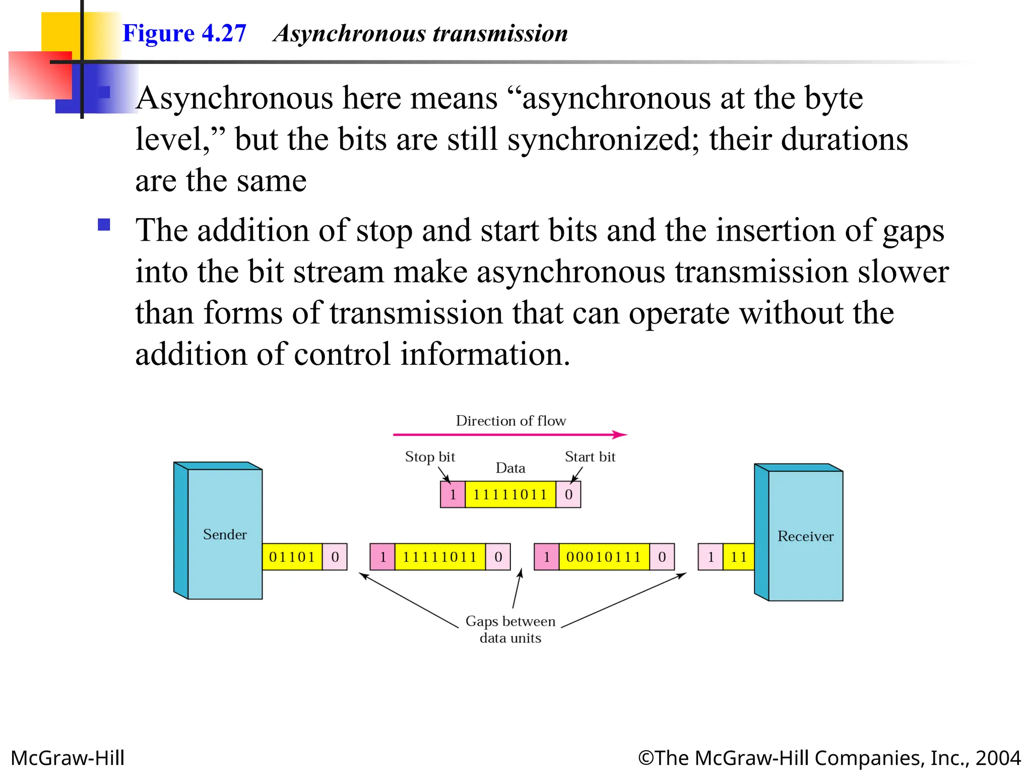
Figure 4.27 Asynchronous transmission
Asynchronous here means “asynchronous at the byte
level,” but the bits are still synchronized; their durations
are the same
The addition of stop and start bits and the insertion of gaps
into the bit stream make asynchronous transmission slower
than forms of transmission that can operate without the
addition of control information.
- 32.
McGraw-Hill ©The McGraw-HillCompanies, Inc., 2004
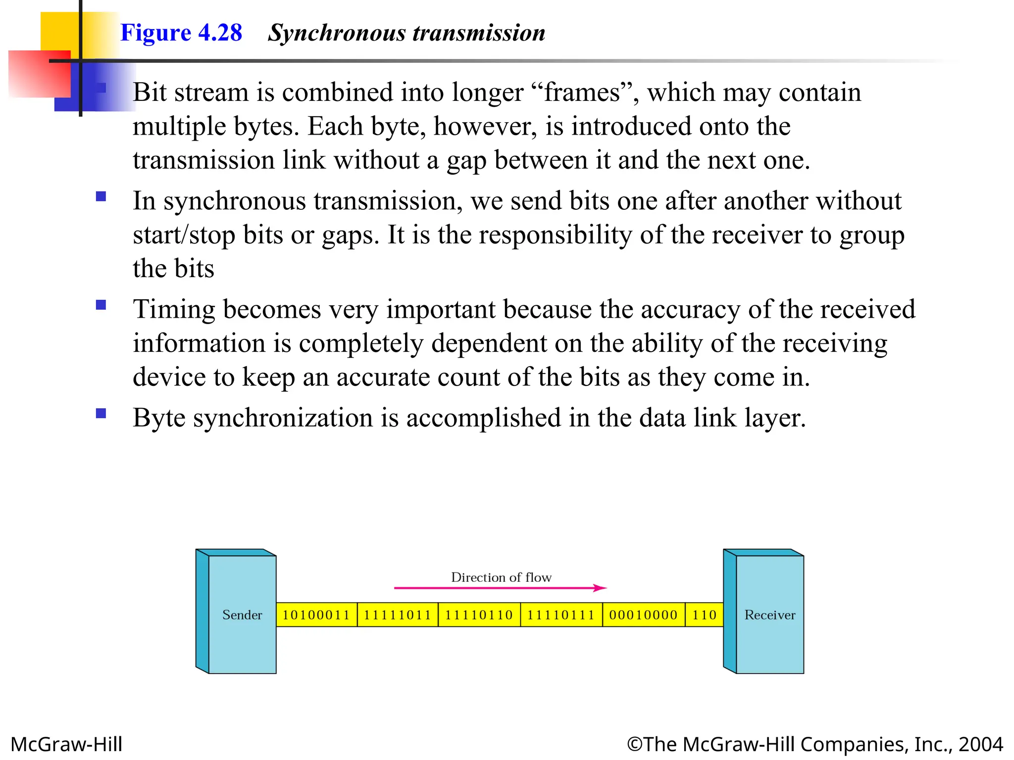
Figure 4.28 Synchronous transmission
Bit stream is combined into longer “frames”, which may contain
multiple bytes. Each byte, however, is introduced onto the
transmission link without a gap between it and the next one.
In synchronous transmission, we send bits one after another without
start/stop bits or gaps. It is the responsibility of the receiver to group
the bits
Timing becomes very important because the accuracy of the received
information is completely dependent on the ability of the receiving
device to keep an accurate count of the bits as they come in.
Byte synchronization is accomplished in the data link layer.