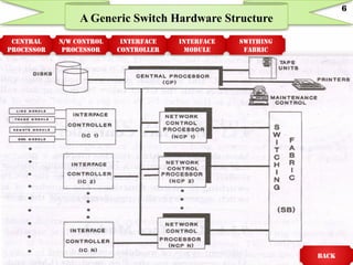
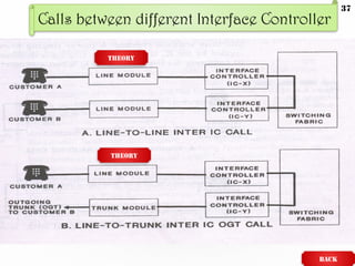
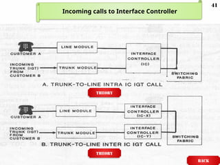
DIGITAL SWITCHING SYSTEMS
A GENERIC DIGITAL SWITCHING
SYSTEM MODEL
PART-b UNIT-8:
Scope
Incoming calls to IC
Introduction
Hardware Architecture
Software Architecture
Recovery strategy
A Simple Call through a DSS
Some Common Characteristics of DSSs
Analysis Report
Calls between different IC
CONEN
TS
Calls within the same IC
2
Introduction
 Different hardware & software components of
digital switch are discussed in detail.
 Extends the functionalities of the hypothetical
digital switch to elucidate the "overall"
hardware and software architectures of a
typical class 5 switch.
main
3
 Creates a generic digital switching system & its
hardware & software architectures.
 Calls through the switch are traced to reveal
the functionalities of an operational DSS.
 System recovery strategy for the hypothetical
digital switch.
Scope
main
4
HARDWARE
Architecture
main
Next
5
A Generic Switch Hardware Structure
CENTRAL
PROCESSOR
N/W CONTROL
PROCESSOR
INTERFACE
CONTROLLER
INTERFACE
MODULE
SWITHING
FABRIC
BACK
6
Central Processor
 CP is employed as a primary processor & is always
duplicated.
 Its function is to provide systemwide control of switching
system.
 Supports secondary processors(NCPs).
 Functions of CP
 Controls high-level functions of the switch & supports operation.
 Controls administration & maintenance functions.
 Controls system recovery process when critical faults occurs in
switching system.
 Maintains subscribers & office data.
 Supports billing system for the switch. BACK
7
Network Control Processors
 The NCP are the secondary processors.
 Purpose is to provide call processing functions and assist
in setting up a path through the switching fabric.
 The NCP are usually duplicated.
 These processors usually interface with the ICs and
provide medium-level call processing support.
 NCP keeps track of all calls that are controlled by its IC
and associated paths assigned for such calls.
 NCP interfaces with the CP or other NCPs to update call
paths on a regular basis, so that other NCPs can get a
"global“ view of all calls.
BACK
8
 Employs a processor-based controller that acts as
a concentrator of all incoming lines & trunks.
 These controllers use time-multiplexed output to
the NCPs & provide time switching functions.
 Number of such controllers in a switch depends on
the engineered size of the co.
Interface Controllers
BACK
9
 Different types of modules are employed in DSS.
 Most common are
Line modules(LMS).
Trunk modules(TMS).
 Depending on the design objective of DSS a line module
may terminate a single line or scores of lines.
 Most switching systems employs smart line cards that
are processor driven & can perform basic call processing
functions. Such as
Line scanning.
Digit collection.
Call supervision.
Interface Modules
Next
10
 TM interface different types of trunks to a
DSS
 A special module is employed to connect isdn
& other digital services to the switch.
 Also employs special module interfaces to
provide enhanced services such as AIN &
packet switching.
 The number & types of modules deployed
depends on the engineering requirement of a
class5 switch.
Interface Modules contd..
BACK
11
 Most DSS employ at least one space switch.
 Concentrators in the ICs are usually time switch.
 S switch is accessible to all NCPs.
 In some case, the switching fabric is partitioned
for use by different NCPs.
 In either case, a dynamic image of network
usage/idle status for the switching fabric is
maintained.
Switching Fabric
BACK
12
Software
Architecture
MAIN
Next
13
SYSTEM LEVEL SOFTWARE
MAINTENANCE
SOFTWARE
CALL
PROCESSING
SOFTWARE
DATABASE
SOFTWARE
NETWORK
SOFTWARE
CONTROLLER
SOFTWARE
PS PS PS
GENERIC SWITCH SOFTWARE
ARCHITECTURE
BACK
14
 Software's at this level are normally a
multitasking OS & is based on a duplex
mainframe computer.
 OS function is to control each application
system(AS) deployed by DSS.
 Basic software systems for a digital switch is
classified as
Maintenance software.
Call processing software.
Database software.
System-Level Software
BACK
15
 Divided into three levels
High-level
 Includes call processing functions that are require support
from a central processing unit or central database.
 Eg: special feature routing, specialized billing, office data
medium-level
 Functions resides in the n/w processing units.
 S/w supports routine call processing functions such as
 Establishing a path through the switching fabric.
 Verifying a subscriber.
 Maintaining a call map.
 These are referred to as network software.
Call Processing Software
Next
16
low-level
 Depending on the architecture of the DSS, many low-
level functions are shared between the ICs & the
LMs.
 These functions may be
 Line scanning.
 Digit collection.
 Attaching service circuits.
 Call supervision.
These are referred to as controller or peripheral
software.
Call Processing Software contd…
BACK
17
 Contents of the database software can
vary greatly between DSSs & within the
switching system product.
 Most DSS employ a database to record
 Office information,
 System recovery parameters,
 System diagnostics,
&
 Billing information.
Database Software
BACK
18
Recovery Strategy
MAIN
level1 level2 level3 manual
19
 Lowest level of initialization for a digital switch.
 Initializes all components that function at level 1control.
 Controlled & directed by the ICs which control LMs, TMs,
& PMs.
 INIT 1 recovery could be directed specifically to initialize
LMs, TMs, & PMs.
 This recovery strategy selectively initializes LMs, TMs, &
PMs based on the severity of the problem.
 This recovery is called as local recovery.
Level 1 Initialization(INIT 1)
BACK
20
 Middle-level of initialization for all components that
functions at level 2 control.
 INIT 2 recovery can be directed specifically for
initializing a specified NCP & a group of NCPs.
 Each NCP controls a number of ICs.
 If a NCP breakdown & the backup NCP cannot switch to
active mode or if a duplex failure of a NCP pair occurs,
then operation of all ICs will be impacted.
 Under this condition, two types of recovery strategy are
considered.
Level 2 Initialization(INIT 1) Next
21
Recovery strategy
 If the problem is
 Due to a NCPs switching from active mode to standby mode &
the switch is not clean, then the connected ICs may help to
stabilize connections by running an INIT 1 initialization on
lines, trunks, & peripherals.
 If that does not help, then INIT 2 needs to be initialize the NCP &
associated ICs .
 Due to a hard duplex failure in the NCP pair, then INIT 2 as to
be run immediately.
 This will impact all connected ICs & associated LMs, TMs, & PMs.
 Multiple-NCP strategy will require initialization of a number of
NCPs & this require a INIT 3.
Level 2 Initialization(INIT 1) contd…
BACK
22
 Highest-level of initialization.
 Functions at level 3 control.
 INIT 3 recovery can directed specifically for
initializing the CP & all NCPs.
 This initialization will be run, when the redundant
CPs fails or the CP switch is not successful & the
DSS cannot fully function with defective CPs.
 Recovery program tries to identify the problem with
the last known good CP.
 Seeks a minimum configuration for its function.
Level 3 Initialization(INIT 1) Next
23
 Depending on the severity of the problem, it will
function with reduced number of NCPs or no NCP
at all.
 Lower load or no load on the system will allow the
CPs to be diagnosed effectively.
 Once CP is fixed, then run INIT 2 to synchronize
all NCPs & bring them up on-line.
 This level of initialization will cause total system
outage.
Level 3 Initialization(INIT 1) contd…
BACK
24
When repeated use of INIT 3 does not recover
the system, then manual recovery becomes
essential.
Under manual recovery, generic program with
the last known good office data & selected
subscribers data is loaded in the digital switch.
Then manual diagnostics or specialized
diagnostics are used to recover the digital
switch.
Manual Recovery
Next
25
 Manual recovery is digital switch specific,
but the basic idea is as follows
 Bring up the system with manual effort.
 The system is updated with last known good generic
program & data.
 Special diagnostic programs & techniques are
needed to identify the problem.
Note:
Analyst should keep in mind that each DSS
is different & may use different strategy for
system recovery.
Manual Recovery contd…
BACK
26
A simple call
through a dSS MAIN
Next
27
 The basic steps necessary to complete a
simple call are as follows
Detect off-hook condition
Identify customers line
Test customers line
Provide dial tone to customer
Provide digits analysis of dialed number
Establish a path between the calling customer and the
called customer.
Ring the called customer.
Detect answer and establish cut-through path.
Supervise both lines for disconnect.
Detect on-hook condition and disconnect.
Next
28
Simple Call Flowchart
BACK
29
Calls within the
same IC MAIN
Next
30
Call within the same Interface Controller
BACK
THEORY
THEORY
31
 Customer A goes off-hook to call customer B, the call
origination request is detected by LM.
 Sends a message to the IC which in turn sends a message to the
NCP.
 NCP validates customer A’s line.
 IC attaches a digit receiver to the line & provides dial-tone to
customer.
 After the first digit dial, the LM removes the dial-tone.
 Dialed digits are collected & sent to the CP for digit analysis.
 If the dialed number is valid, the NCPs assign time-slots for a
call connection path b/w customer A & customer B.
 If the dialed number is not valid, an announcement or tone is
given to the customer.
Explanation for Line to Line Intra IC
Call
Next
32
 Customer B’s line is checked for busy/idle status & a power
ringing is applied.
 An audible ringing is simultaneously applied to customer
A’s line.
 When customer B answers, a cut-through path through the
switching fabric is provided via previously assigned time-
slots.
 First leg of call from customer A uses T switch of IC, second
leg uses an S switch through switching fabric, & third leg
to customer B uses another T switch through IC.
 If either customer disconnects, the LM detects the on-hook
condition & idles the connection.
Explanation contd….
BACK
33
 Customer A goes off-hook to call customer B, who is served by
another central office.
 Call origination request is detected by the LM.
 Sends a message to the IC which in turn sends a message to
the NCP.
 NCP validates customer A’s line.
 IC attaches a digit receiver to the line & provides dial-tone to
customer.
 After the first digit dial, the LM removes the dial-tone.
 Dialed digits are collected & sent to the CP for digit analysis.
 If the dialed number is valid, the NCPs assign time-slots for a call
connection path b/w customer A & an outgoing trunk for customer
B’s CO or tandem exchange.
Explanation for Line to Line Intra IC OGT Call
Next
34
 If the dialed number is not valid, an announcement or tone
is given to the customer.
 Terminating CO checks customer B’s line for busy/idle
status & a power ringing is applied.
 An audible ringing is simultaneously applied to customer
A’s line.
 When customer B answers, a cut-through path through the
switching fabric is provided via previously assigned time-
slots.
 As in line-to-line call, each CO uses TST connection.
 If either customer disconnects, the LM of either CO detects
the on-hook condition & idles the connection.
 Call supervision is provided by originating CO
Explanation contd….
BACK
35
Calls between the
different IC
MAIN
Next
36
Calls between different Interface Controller
BACK
THEORY
THEORY
37
 Customer A calls customer B, located in another
IC.
 Same as line-to-line intra-IC call, except a path
through IC-X & IC-Y is established for the call.
 Co-ordination between the associated NCPs is
provided by the CP.
Explanation for Line to Line Inter IC Call
BACK
38
 Customer A calls customer B, located in another
CO, & a different IC is selected.
 Same as line-to-trunk intra-IC OGT call, except a
path through IC-X & IC-Y is established for the
call.
 Co-ordination between the associated NCPs is
provided by the CP.
Explanation for Line to Trunk Inter IC Call
BACK
39
Incoming calls to
Interface Controller
MAIN
Next
40
Incoming calls to Interface Controller
BACK
theory
theory
41
Customer A is called by customer A,
who is served by another CO, & the
incoming trunk selected lies in the same
IC
Explanation for Trunk-to-Line Intra-IC IGT Call
Next
42
The CO for customer B homes into customer A's CO
directly or through a tandem office.
It connects to customer A's CO via an incoming trunk
(IGT).
If the trunk and customer A's line are in the same
interface controller, a path is established through the
switching fabric to the LM of customer A.
 The associated NCP performs all time-slot
assignments for the IGT and customer A‘s line.
Line A is validated, and its idle/busy status is checked.
A power ringing to customer A's line is applied by the
IC, and an audible ringing is simultaneously transmitted to
customer B's line via the IGT
Explanation for Trunk-to-Line Intra-IC IGT Call
contd…
Next
43
When customer A answers, a cut through path through
the switching fabric is provided via previously assigned
time slots.
 As in line-to-line calls, each CO uses a TST connection.
If either customer disconnects, the LM of either CO detects
the on-hook condition and idles the connection.
Call supervision is provided by the originating CO .
Explanation for Trunk-to-Line Intra-IC IGT Call
contd…
BACK
44
Customer A is called by customer B, who is
served by another central office, and the incoming
trunk selected lies in a different interface
controller.
This is the same as a line-to-trunk intra-IC
IGT call, except a path through IC-X and IC-Y is
established.
Explanation for Trunk-to-Line Inter-IC IGT
BACK
45
Some Common
Characteristics of
DSSs main
Next
46
1. Dual capability:
Most digital switching systems covered, which are primarily
class 5, can also have tandem/toll or class 4 capabilities.
Most of the large digital switching systems can terminate
approximately 100,000 lines or 60,000 trunks.
2. Traffic capacity:
In a distributed environment, this depends on the digital
switch configuration, and it can go as high as 2,000,000 busy-hour
call attempts (BHCAs).
3.Architecture—hardware:
Most digital switching systems have a quasi-distributed hardware
architecture.
All digital switching systems employ multiple processor
subsystems.
Some Common Characteristics of Digital Switching Systems
Next
47
4.Architecture—software
 Most digital switching systems maintain a modular software
design, sometimes through layering or through functionalities
 They have operating systems under which application systems
function.
 They all support database systems for office records, subscriber
records, administration records, etc.
 They all have maintenance subsystems that support diagnostic
and switch maintenance processes.
 They also support billing systems for subscribers such as the
automatic messaging system.
5.Switching fabric:
 Most DSSs utilize time-space-time (TST) mode for switching calls.
Some Common Characteristics of Digital Switching Systems
6.Advanced feature support:
 Most DSSs can support advanced features such as ISDN, STP,
SCF and AIN.
Next
48
7.Remote operation:
 Most DSSs have remote switching modules (RSMs) to support
switching functions in a remote location.
Most remote switching systems have standalone capabilities, so
if the main switching system (host) goes down, the remote units can
still switch local calls.
NOTE:
Many Internet users now connect to their Internet providers
through class 5 COs and keep the connection up for long periods.
The integration of voice, data, and full-motion video as required by
the Internet and other services will need to be switched through a class 5
digital switching system.
The use of ATM and optical links using SONET will dominate the
switching markets of the future.
Some Common Characteristics of Digital Switching Systems
BACK
49
Analysis Report
main
Next
50
Analysis Report
System
Description
Product Support
Operation,
Administration,
and Maintenance
Reliability
Analysis
BACK
51
System overview : Describe system-level functional blocks of the
digital switch.
System Description
System recovery strategy : Describe different levels of system
initialization and typical times for system recovery for each level of
initialization.
Capacity : Cover busy-hour call attempts of the digital switch for desired
configurations.
Hardware description : Detailed description of all important
hardware components of the digital switch required for desired
configuration of equipment.
Software description : Describe the main software architecture of
the digital switch with all major software components identified.
Call processing : Describe the flow of different types of calls through
the digital switch.
Features list : Describe all base features and optional features
BACK 52
Operation, Administration, and Maintenance
Database management :
Describe all databases that need to be managed, e.g., office
database, translation database, and billing database.
OSS interfaces :
Describe all types of operational support system
interfaces.
BACK
53
Reliability Analysis
Component failure rates :
Describe the component failure rates for different circuit
packs used in the digital switch.
Software reliability analysis :
Describe the results of the software analysis of the
digital switching system software.
System reliability :
Describe the results of hardware modeling of various
subsystems of the digital switch.
BACK
54
Technical assistance:
Describe different levels of technical support that the
digital switching supplier provides and the escalation process
and time limits within which the supplier will correct the fault.
Documentation:
List all documents that will be supplied to maintain
the DSS and how often it will be updated.
Fault reporting system:
Describe a fault-reporting system that tracks all faults
discovered by the operator of the DSS.
Training:
List all training courses available for telephone
company personnel who will use and maintain the DSS.
Product Support BACK 55
main
56
main
57

Digital Switching System module 5 UNIT8 RO.pptx

  • 1.
    DIGITAL SWITCHING SYSTEMS AGENERIC DIGITAL SWITCHING SYSTEM MODEL PART-b UNIT-8:
  • 2.
    Scope Incoming calls toIC Introduction Hardware Architecture Software Architecture Recovery strategy A Simple Call through a DSS Some Common Characteristics of DSSs Analysis Report Calls between different IC CONEN TS Calls within the same IC 2
  • 3.
    Introduction  Different hardware& software components of digital switch are discussed in detail.  Extends the functionalities of the hypothetical digital switch to elucidate the "overall" hardware and software architectures of a typical class 5 switch. main 3
  • 4.
     Creates ageneric digital switching system & its hardware & software architectures.  Calls through the switch are traced to reveal the functionalities of an operational DSS.  System recovery strategy for the hypothetical digital switch. Scope main 4
  • 5.
  • 6.
    A Generic SwitchHardware Structure CENTRAL PROCESSOR N/W CONTROL PROCESSOR INTERFACE CONTROLLER INTERFACE MODULE SWITHING FABRIC BACK 6
  • 7.
    Central Processor  CPis employed as a primary processor & is always duplicated.  Its function is to provide systemwide control of switching system.  Supports secondary processors(NCPs).  Functions of CP  Controls high-level functions of the switch & supports operation.  Controls administration & maintenance functions.  Controls system recovery process when critical faults occurs in switching system.  Maintains subscribers & office data.  Supports billing system for the switch. BACK 7
  • 8.
    Network Control Processors The NCP are the secondary processors.  Purpose is to provide call processing functions and assist in setting up a path through the switching fabric.  The NCP are usually duplicated.  These processors usually interface with the ICs and provide medium-level call processing support.  NCP keeps track of all calls that are controlled by its IC and associated paths assigned for such calls.  NCP interfaces with the CP or other NCPs to update call paths on a regular basis, so that other NCPs can get a "global“ view of all calls. BACK 8
  • 9.
     Employs aprocessor-based controller that acts as a concentrator of all incoming lines & trunks.  These controllers use time-multiplexed output to the NCPs & provide time switching functions.  Number of such controllers in a switch depends on the engineered size of the co. Interface Controllers BACK 9
  • 10.
     Different typesof modules are employed in DSS.  Most common are Line modules(LMS). Trunk modules(TMS).  Depending on the design objective of DSS a line module may terminate a single line or scores of lines.  Most switching systems employs smart line cards that are processor driven & can perform basic call processing functions. Such as Line scanning. Digit collection. Call supervision. Interface Modules Next 10
  • 11.
     TM interfacedifferent types of trunks to a DSS  A special module is employed to connect isdn & other digital services to the switch.  Also employs special module interfaces to provide enhanced services such as AIN & packet switching.  The number & types of modules deployed depends on the engineering requirement of a class5 switch. Interface Modules contd.. BACK 11
  • 12.
     Most DSSemploy at least one space switch.  Concentrators in the ICs are usually time switch.  S switch is accessible to all NCPs.  In some case, the switching fabric is partitioned for use by different NCPs.  In either case, a dynamic image of network usage/idle status for the switching fabric is maintained. Switching Fabric BACK 12
  • 13.
  • 14.
  • 15.
     Software's atthis level are normally a multitasking OS & is based on a duplex mainframe computer.  OS function is to control each application system(AS) deployed by DSS.  Basic software systems for a digital switch is classified as Maintenance software. Call processing software. Database software. System-Level Software BACK 15
  • 16.
     Divided intothree levels High-level  Includes call processing functions that are require support from a central processing unit or central database.  Eg: special feature routing, specialized billing, office data medium-level  Functions resides in the n/w processing units.  S/w supports routine call processing functions such as  Establishing a path through the switching fabric.  Verifying a subscriber.  Maintaining a call map.  These are referred to as network software. Call Processing Software Next 16
  • 17.
    low-level  Depending onthe architecture of the DSS, many low- level functions are shared between the ICs & the LMs.  These functions may be  Line scanning.  Digit collection.  Attaching service circuits.  Call supervision. These are referred to as controller or peripheral software. Call Processing Software contd… BACK 17
  • 18.
     Contents ofthe database software can vary greatly between DSSs & within the switching system product.  Most DSS employ a database to record  Office information,  System recovery parameters,  System diagnostics, &  Billing information. Database Software BACK 18
  • 19.
  • 20.
     Lowest levelof initialization for a digital switch.  Initializes all components that function at level 1control.  Controlled & directed by the ICs which control LMs, TMs, & PMs.  INIT 1 recovery could be directed specifically to initialize LMs, TMs, & PMs.  This recovery strategy selectively initializes LMs, TMs, & PMs based on the severity of the problem.  This recovery is called as local recovery. Level 1 Initialization(INIT 1) BACK 20
  • 21.
     Middle-level ofinitialization for all components that functions at level 2 control.  INIT 2 recovery can be directed specifically for initializing a specified NCP & a group of NCPs.  Each NCP controls a number of ICs.  If a NCP breakdown & the backup NCP cannot switch to active mode or if a duplex failure of a NCP pair occurs, then operation of all ICs will be impacted.  Under this condition, two types of recovery strategy are considered. Level 2 Initialization(INIT 1) Next 21
  • 22.
    Recovery strategy  Ifthe problem is  Due to a NCPs switching from active mode to standby mode & the switch is not clean, then the connected ICs may help to stabilize connections by running an INIT 1 initialization on lines, trunks, & peripherals.  If that does not help, then INIT 2 needs to be initialize the NCP & associated ICs .  Due to a hard duplex failure in the NCP pair, then INIT 2 as to be run immediately.  This will impact all connected ICs & associated LMs, TMs, & PMs.  Multiple-NCP strategy will require initialization of a number of NCPs & this require a INIT 3. Level 2 Initialization(INIT 1) contd… BACK 22
  • 23.
     Highest-level ofinitialization.  Functions at level 3 control.  INIT 3 recovery can directed specifically for initializing the CP & all NCPs.  This initialization will be run, when the redundant CPs fails or the CP switch is not successful & the DSS cannot fully function with defective CPs.  Recovery program tries to identify the problem with the last known good CP.  Seeks a minimum configuration for its function. Level 3 Initialization(INIT 1) Next 23
  • 24.
     Depending onthe severity of the problem, it will function with reduced number of NCPs or no NCP at all.  Lower load or no load on the system will allow the CPs to be diagnosed effectively.  Once CP is fixed, then run INIT 2 to synchronize all NCPs & bring them up on-line.  This level of initialization will cause total system outage. Level 3 Initialization(INIT 1) contd… BACK 24
  • 25.
    When repeated useof INIT 3 does not recover the system, then manual recovery becomes essential. Under manual recovery, generic program with the last known good office data & selected subscribers data is loaded in the digital switch. Then manual diagnostics or specialized diagnostics are used to recover the digital switch. Manual Recovery Next 25
  • 26.
     Manual recoveryis digital switch specific, but the basic idea is as follows  Bring up the system with manual effort.  The system is updated with last known good generic program & data.  Special diagnostic programs & techniques are needed to identify the problem. Note: Analyst should keep in mind that each DSS is different & may use different strategy for system recovery. Manual Recovery contd… BACK 26
  • 27.
    A simple call througha dSS MAIN Next 27
  • 28.
     The basicsteps necessary to complete a simple call are as follows Detect off-hook condition Identify customers line Test customers line Provide dial tone to customer Provide digits analysis of dialed number Establish a path between the calling customer and the called customer. Ring the called customer. Detect answer and establish cut-through path. Supervise both lines for disconnect. Detect on-hook condition and disconnect. Next 28
  • 29.
  • 30.
    Calls within the sameIC MAIN Next 30
  • 31.
    Call within thesame Interface Controller BACK THEORY THEORY 31
  • 32.
     Customer Agoes off-hook to call customer B, the call origination request is detected by LM.  Sends a message to the IC which in turn sends a message to the NCP.  NCP validates customer A’s line.  IC attaches a digit receiver to the line & provides dial-tone to customer.  After the first digit dial, the LM removes the dial-tone.  Dialed digits are collected & sent to the CP for digit analysis.  If the dialed number is valid, the NCPs assign time-slots for a call connection path b/w customer A & customer B.  If the dialed number is not valid, an announcement or tone is given to the customer. Explanation for Line to Line Intra IC Call Next 32
  • 33.
     Customer B’sline is checked for busy/idle status & a power ringing is applied.  An audible ringing is simultaneously applied to customer A’s line.  When customer B answers, a cut-through path through the switching fabric is provided via previously assigned time- slots.  First leg of call from customer A uses T switch of IC, second leg uses an S switch through switching fabric, & third leg to customer B uses another T switch through IC.  If either customer disconnects, the LM detects the on-hook condition & idles the connection. Explanation contd…. BACK 33
  • 34.
     Customer Agoes off-hook to call customer B, who is served by another central office.  Call origination request is detected by the LM.  Sends a message to the IC which in turn sends a message to the NCP.  NCP validates customer A’s line.  IC attaches a digit receiver to the line & provides dial-tone to customer.  After the first digit dial, the LM removes the dial-tone.  Dialed digits are collected & sent to the CP for digit analysis.  If the dialed number is valid, the NCPs assign time-slots for a call connection path b/w customer A & an outgoing trunk for customer B’s CO or tandem exchange. Explanation for Line to Line Intra IC OGT Call Next 34
  • 35.
     If thedialed number is not valid, an announcement or tone is given to the customer.  Terminating CO checks customer B’s line for busy/idle status & a power ringing is applied.  An audible ringing is simultaneously applied to customer A’s line.  When customer B answers, a cut-through path through the switching fabric is provided via previously assigned time- slots.  As in line-to-line call, each CO uses TST connection.  If either customer disconnects, the LM of either CO detects the on-hook condition & idles the connection.  Call supervision is provided by originating CO Explanation contd…. BACK 35
  • 36.
  • 37.
    Calls between differentInterface Controller BACK THEORY THEORY 37
  • 38.
     Customer Acalls customer B, located in another IC.  Same as line-to-line intra-IC call, except a path through IC-X & IC-Y is established for the call.  Co-ordination between the associated NCPs is provided by the CP. Explanation for Line to Line Inter IC Call BACK 38
  • 39.
     Customer Acalls customer B, located in another CO, & a different IC is selected.  Same as line-to-trunk intra-IC OGT call, except a path through IC-X & IC-Y is established for the call.  Co-ordination between the associated NCPs is provided by the CP. Explanation for Line to Trunk Inter IC Call BACK 39
  • 40.
    Incoming calls to InterfaceController MAIN Next 40
  • 41.
    Incoming calls toInterface Controller BACK theory theory 41
  • 42.
    Customer A iscalled by customer A, who is served by another CO, & the incoming trunk selected lies in the same IC Explanation for Trunk-to-Line Intra-IC IGT Call Next 42
  • 43.
    The CO forcustomer B homes into customer A's CO directly or through a tandem office. It connects to customer A's CO via an incoming trunk (IGT). If the trunk and customer A's line are in the same interface controller, a path is established through the switching fabric to the LM of customer A.  The associated NCP performs all time-slot assignments for the IGT and customer A‘s line. Line A is validated, and its idle/busy status is checked. A power ringing to customer A's line is applied by the IC, and an audible ringing is simultaneously transmitted to customer B's line via the IGT Explanation for Trunk-to-Line Intra-IC IGT Call contd… Next 43
  • 44.
    When customer Aanswers, a cut through path through the switching fabric is provided via previously assigned time slots.  As in line-to-line calls, each CO uses a TST connection. If either customer disconnects, the LM of either CO detects the on-hook condition and idles the connection. Call supervision is provided by the originating CO . Explanation for Trunk-to-Line Intra-IC IGT Call contd… BACK 44
  • 45.
    Customer A iscalled by customer B, who is served by another central office, and the incoming trunk selected lies in a different interface controller. This is the same as a line-to-trunk intra-IC IGT call, except a path through IC-X and IC-Y is established. Explanation for Trunk-to-Line Inter-IC IGT BACK 45
  • 46.
  • 47.
    1. Dual capability: Mostdigital switching systems covered, which are primarily class 5, can also have tandem/toll or class 4 capabilities. Most of the large digital switching systems can terminate approximately 100,000 lines or 60,000 trunks. 2. Traffic capacity: In a distributed environment, this depends on the digital switch configuration, and it can go as high as 2,000,000 busy-hour call attempts (BHCAs). 3.Architecture—hardware: Most digital switching systems have a quasi-distributed hardware architecture. All digital switching systems employ multiple processor subsystems. Some Common Characteristics of Digital Switching Systems Next 47
  • 48.
    4.Architecture—software  Most digitalswitching systems maintain a modular software design, sometimes through layering or through functionalities  They have operating systems under which application systems function.  They all support database systems for office records, subscriber records, administration records, etc.  They all have maintenance subsystems that support diagnostic and switch maintenance processes.  They also support billing systems for subscribers such as the automatic messaging system. 5.Switching fabric:  Most DSSs utilize time-space-time (TST) mode for switching calls. Some Common Characteristics of Digital Switching Systems 6.Advanced feature support:  Most DSSs can support advanced features such as ISDN, STP, SCF and AIN. Next 48
  • 49.
    7.Remote operation:  MostDSSs have remote switching modules (RSMs) to support switching functions in a remote location. Most remote switching systems have standalone capabilities, so if the main switching system (host) goes down, the remote units can still switch local calls. NOTE: Many Internet users now connect to their Internet providers through class 5 COs and keep the connection up for long periods. The integration of voice, data, and full-motion video as required by the Internet and other services will need to be switched through a class 5 digital switching system. The use of ATM and optical links using SONET will dominate the switching markets of the future. Some Common Characteristics of Digital Switching Systems BACK 49
  • 50.
  • 51.
  • 52.
    System overview :Describe system-level functional blocks of the digital switch. System Description System recovery strategy : Describe different levels of system initialization and typical times for system recovery for each level of initialization. Capacity : Cover busy-hour call attempts of the digital switch for desired configurations. Hardware description : Detailed description of all important hardware components of the digital switch required for desired configuration of equipment. Software description : Describe the main software architecture of the digital switch with all major software components identified. Call processing : Describe the flow of different types of calls through the digital switch. Features list : Describe all base features and optional features BACK 52
  • 53.
    Operation, Administration, andMaintenance Database management : Describe all databases that need to be managed, e.g., office database, translation database, and billing database. OSS interfaces : Describe all types of operational support system interfaces. BACK 53
  • 54.
    Reliability Analysis Component failurerates : Describe the component failure rates for different circuit packs used in the digital switch. Software reliability analysis : Describe the results of the software analysis of the digital switching system software. System reliability : Describe the results of hardware modeling of various subsystems of the digital switch. BACK 54
  • 55.
    Technical assistance: Describe differentlevels of technical support that the digital switching supplier provides and the escalation process and time limits within which the supplier will correct the fault. Documentation: List all documents that will be supplied to maintain the DSS and how often it will be updated. Fault reporting system: Describe a fault-reporting system that tracks all faults discovered by the operator of the DSS. Training: List all training courses available for telephone company personnel who will use and maintain the DSS. Product Support BACK 55
  • 56.
  • 57.