Download to read offline
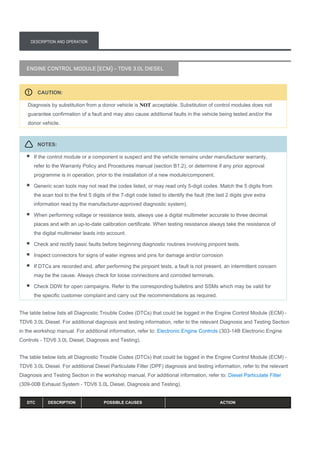
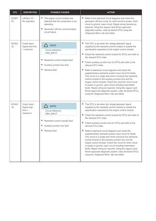
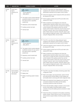
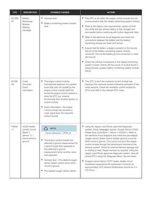
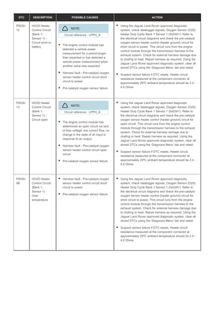
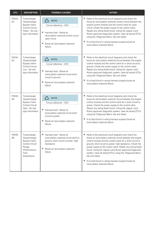
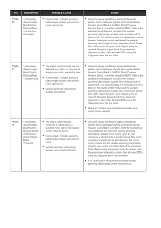
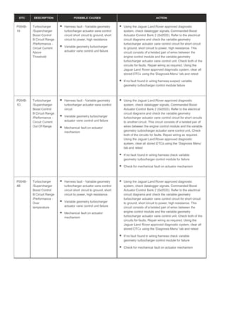
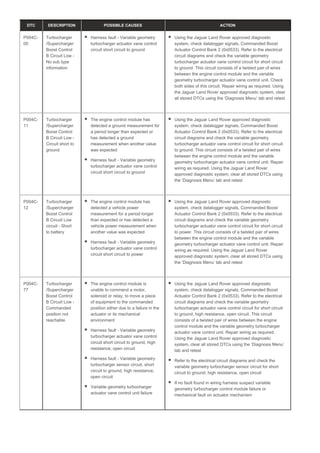
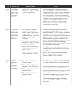
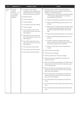
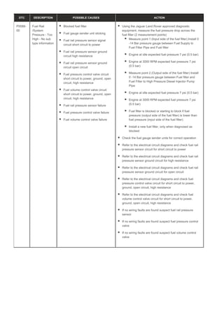
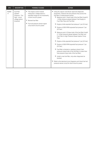
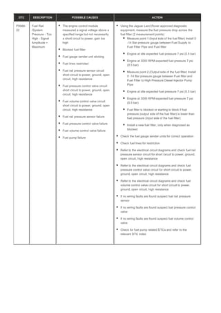
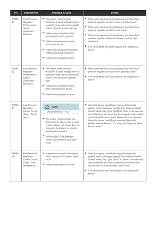
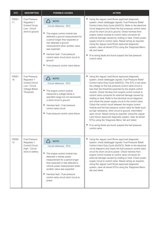
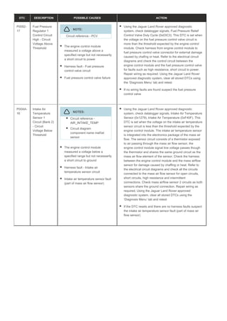
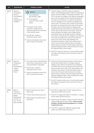
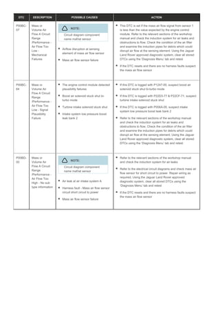
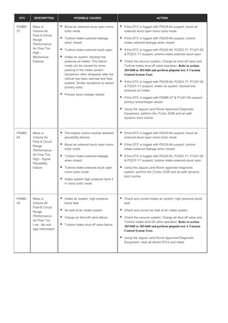
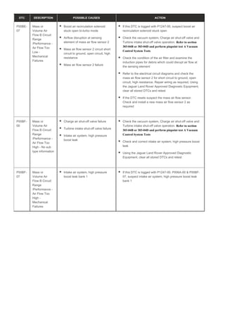
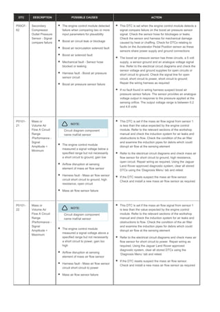
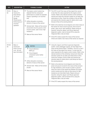
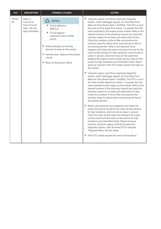
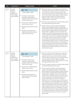
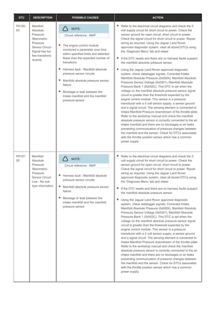
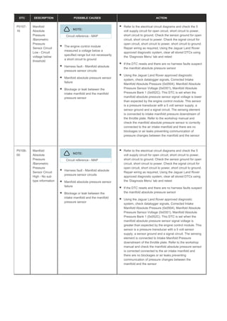
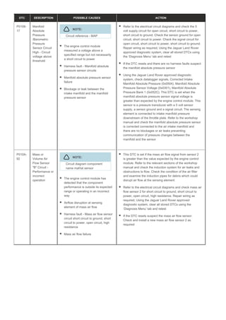
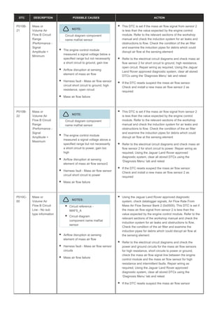
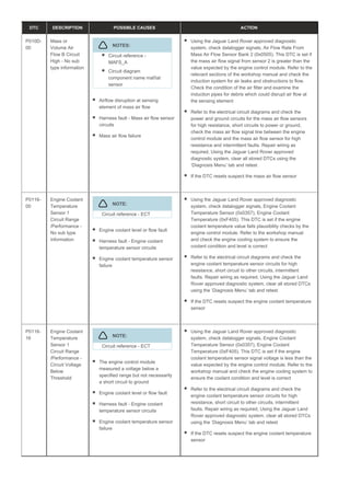
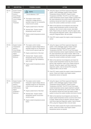
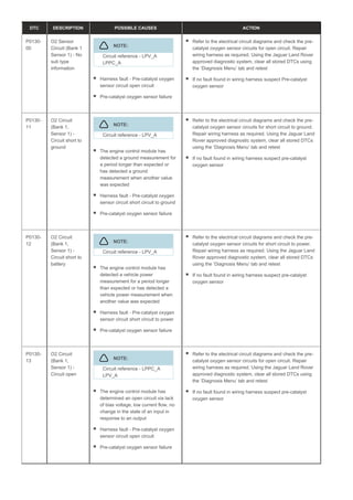
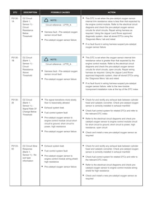
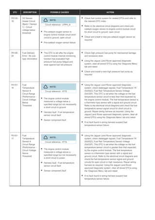
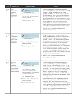
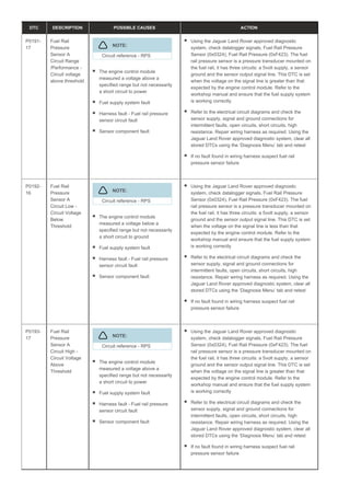
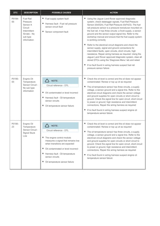
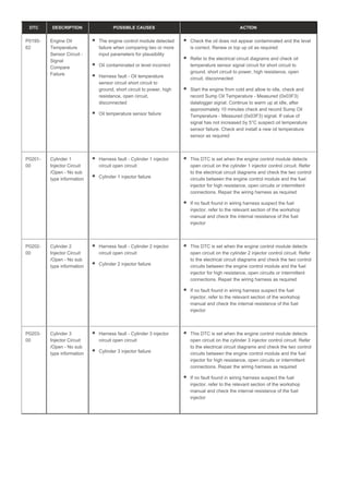
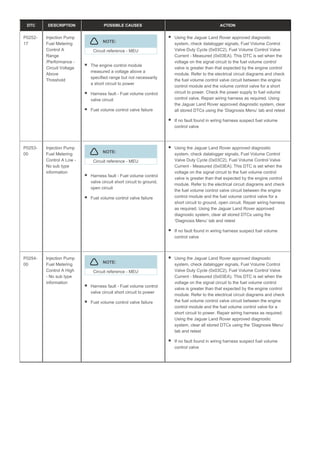
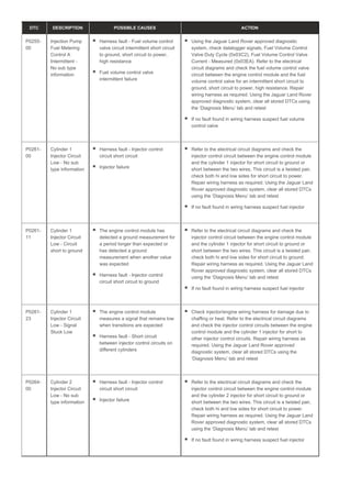
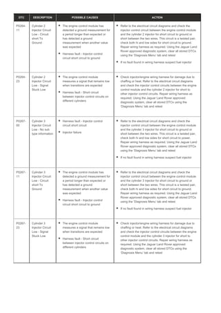
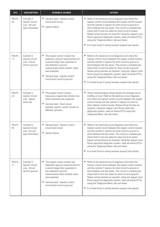
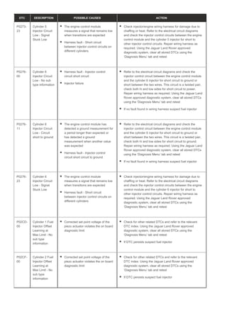
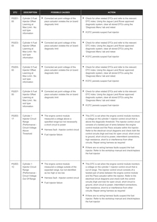
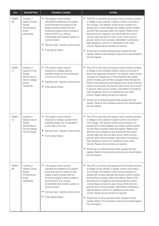
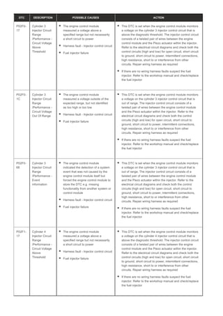
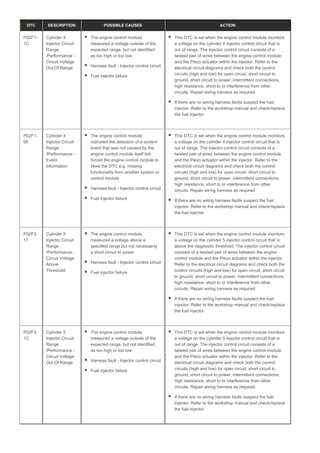

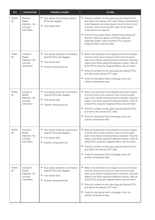
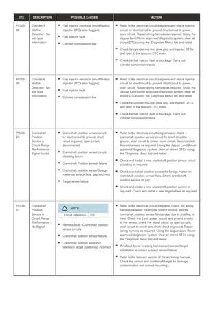
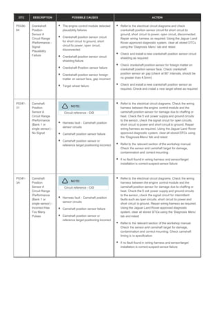
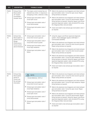
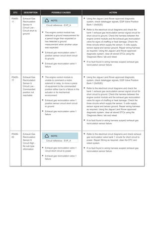
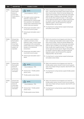
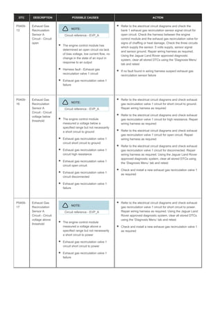
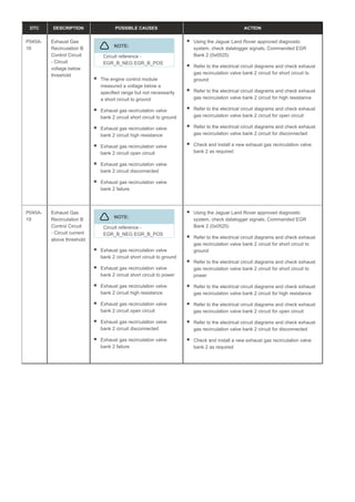
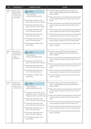
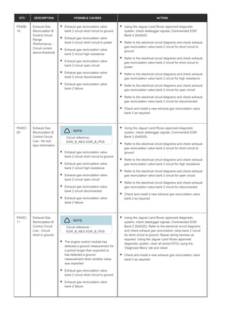
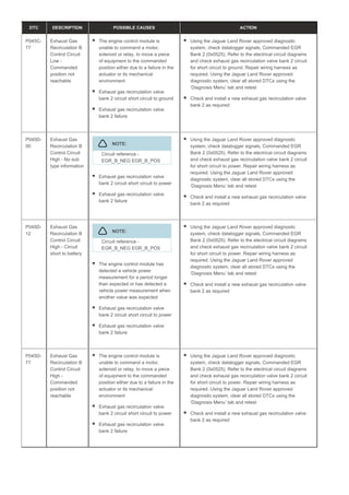
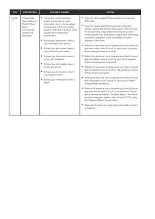
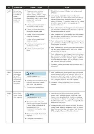
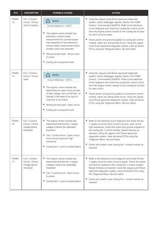
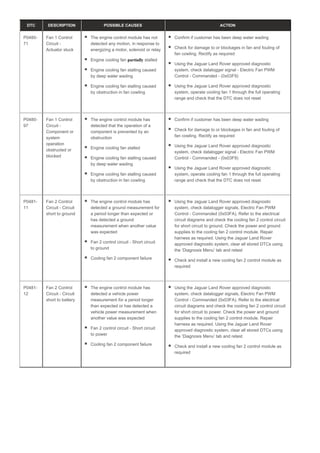
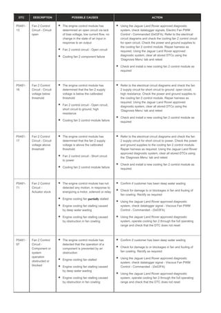
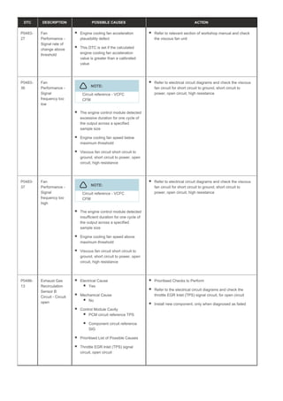
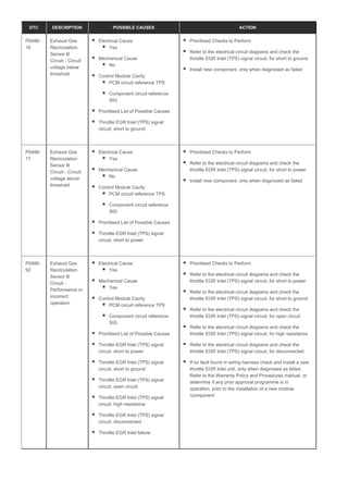
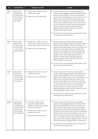
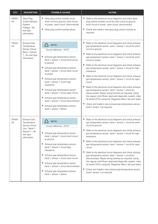
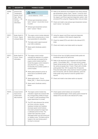
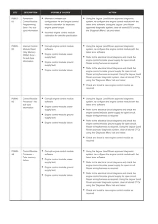
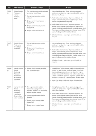
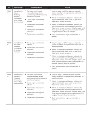
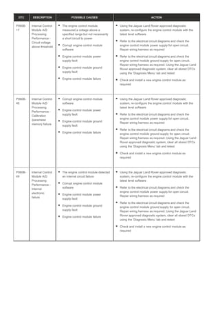
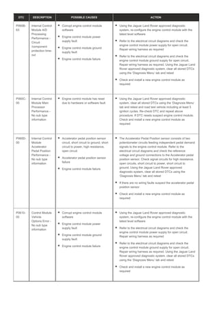
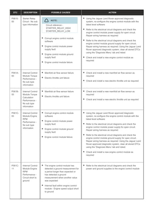
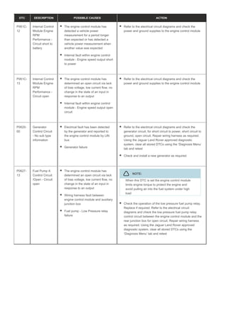
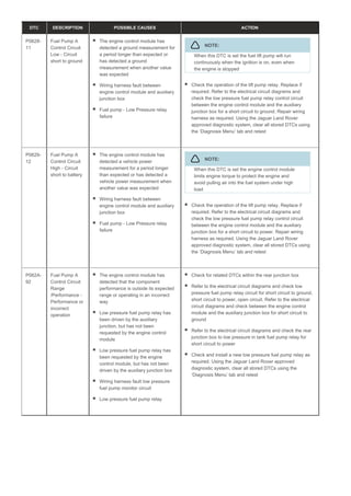
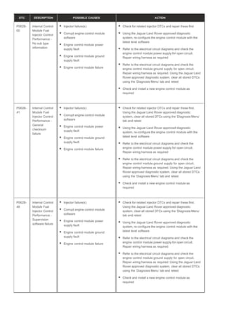
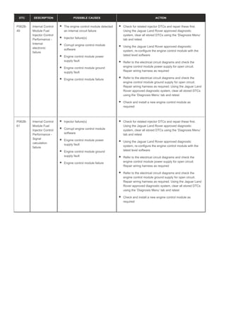
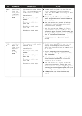
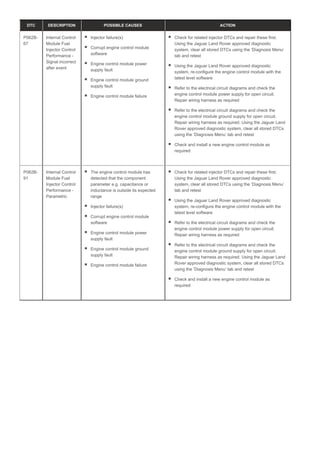
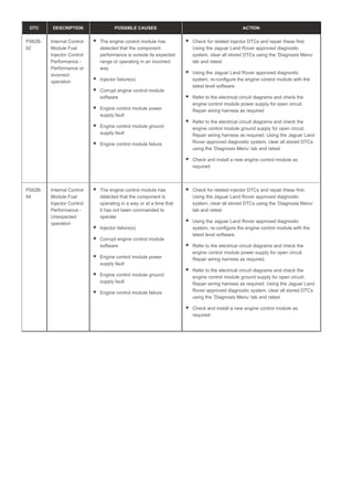
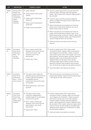
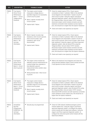
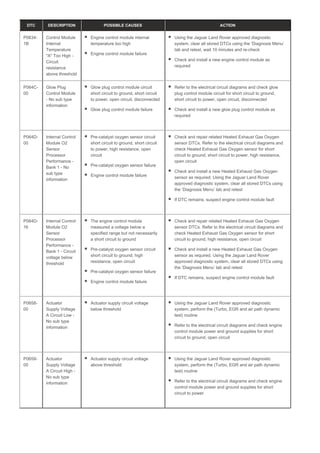
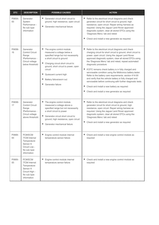
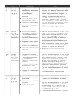
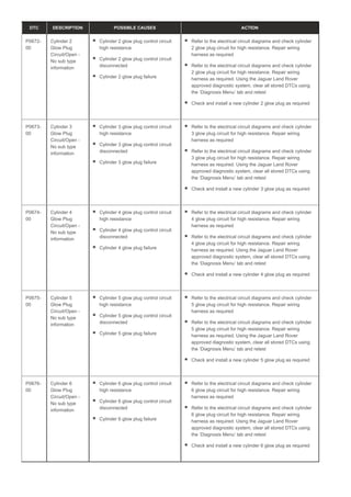
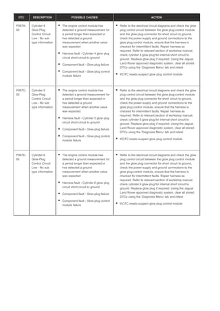
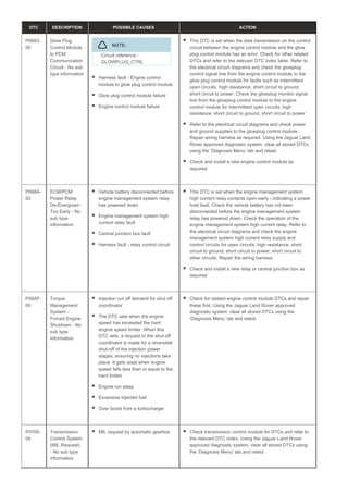
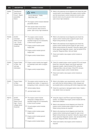
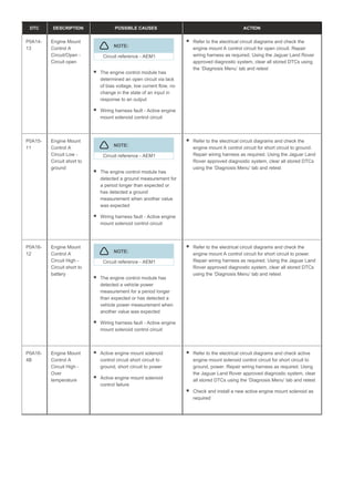
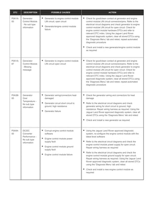
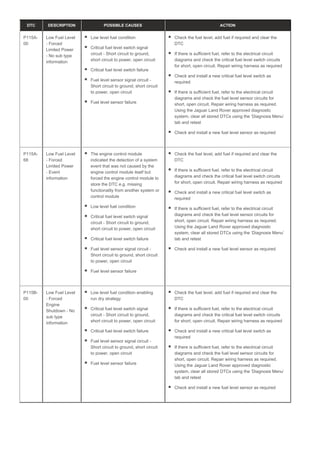
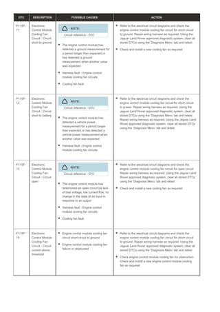
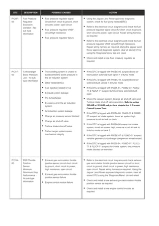
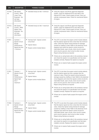

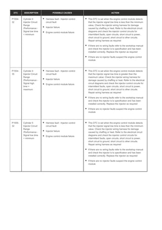

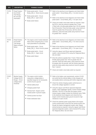
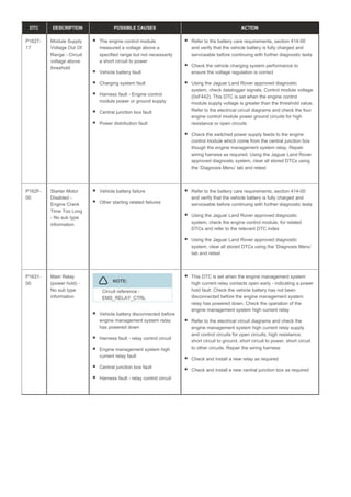
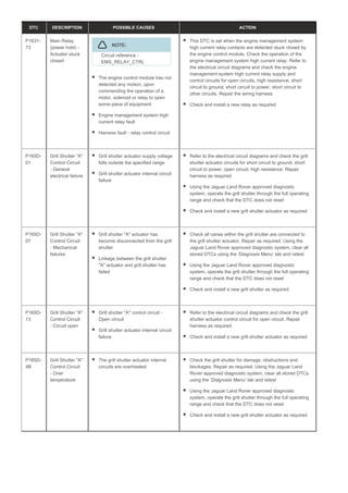
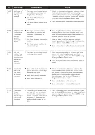
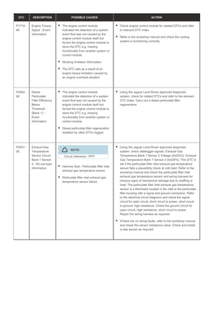

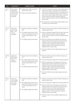
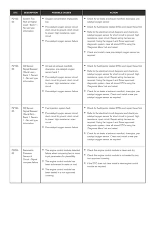
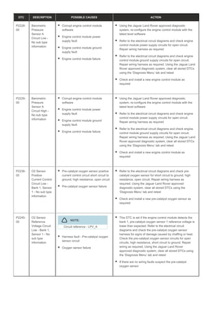
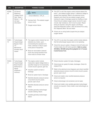
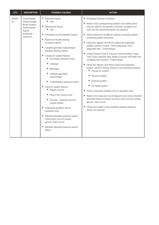
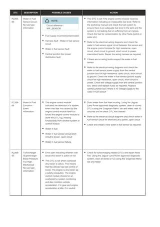
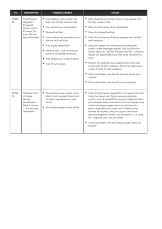
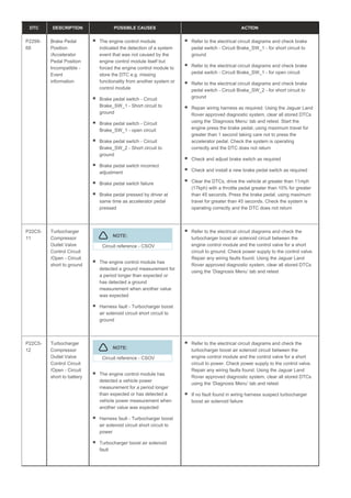
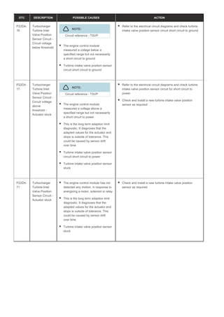
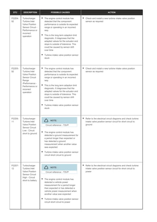
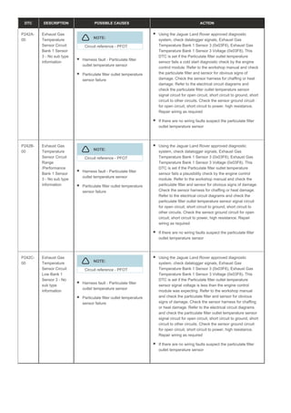
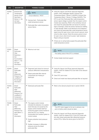
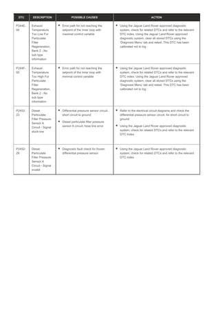
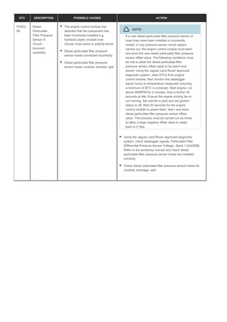
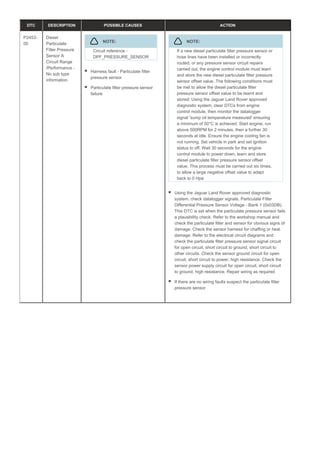
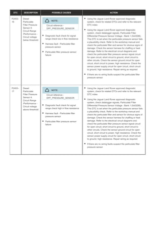
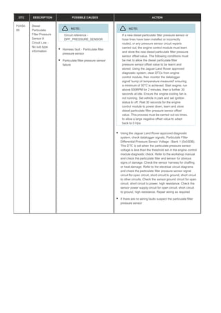

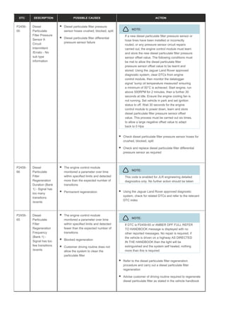
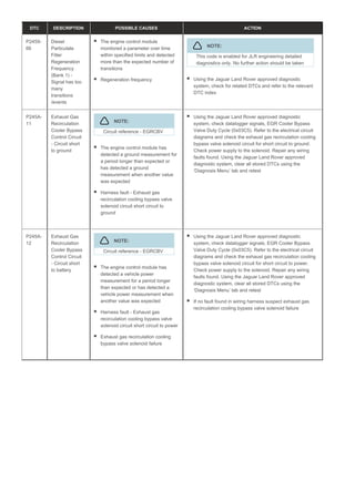
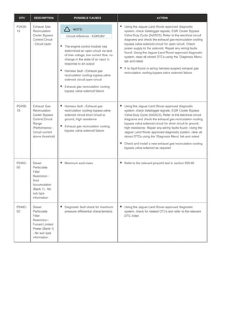
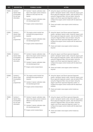
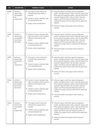
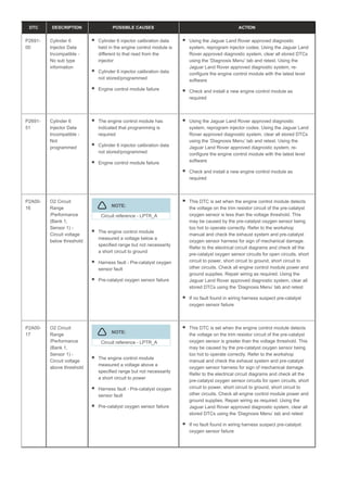
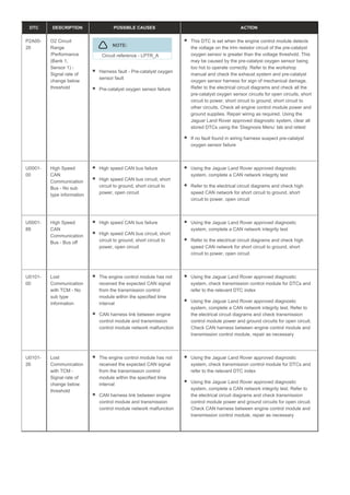
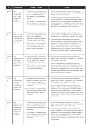
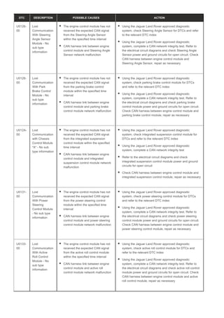
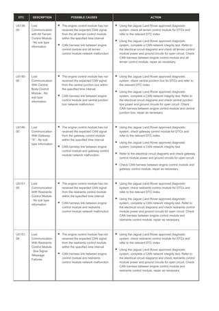
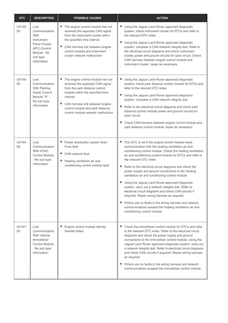
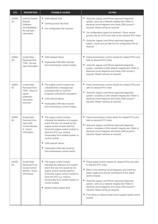
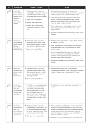
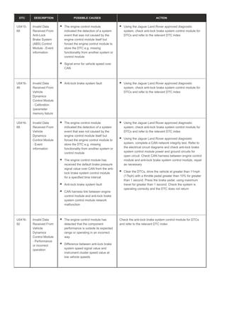
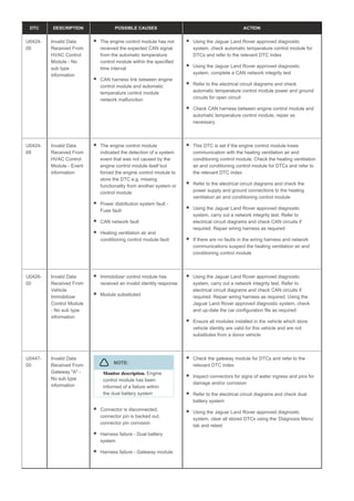
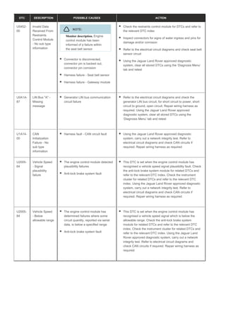
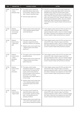


The document provides diagnostic information for the TDV6 3.0L diesel engine control module (ECM), detailing various diagnostic trouble codes (DTCs) along with their possible causes and recommended actions. It emphasizes the importance of using manufacturer-approved diagnostic tools and following specific procedures for accurate fault identification and module/component substitutions. Additionally, it highlights the need for thorough inspections of wiring and connectors to ensure reliable diagnostics and repairs.