Download to read offline

![CMOS⇒CMOS(Mode0)
VCC=5[V], VDD=10[V]
M1
MbreakN
M2
MbreakN
M3
MbreakN
M4
MbreakN
M5
MbreakN
M6
MbreakP
M7
MbreakP
M8
MbreakP
M9
MbreakP
M10
MbreakP
00
0 0
a
V V
c
b
Vin
VCC2
5Vdc
VDD2
10Vdc
0 0
V1
TD = 0
TF = 50n
PW = 200n
PER = 500n
V1 = 0
TR = 50n
V2 = 5
0
1
R5
50
0
1
T1
TD = 135n
Z0 = 50
Vout
CL
50p
0
C1
1.35p
C2
1.65p
4](https://image.slidesharecdn.com/mc14504b-200821085436/85/Device-Modeling-of-MC14504B-Using-PSpice-4-320.jpg)
![CMOS⇒CMOS(Mode0)
VCC=5[V], VDD=10[V]
5](https://image.slidesharecdn.com/mc14504b-200821085436/85/Device-Modeling-of-MC14504B-Using-PSpice-5-320.jpg)
![CMOS⇒CMOS(Mode0)
VCC=10[V], VDD=5V]
M1
MbreakN
M2
MbreakN
M3
MbreakN
M4
MbreakN
M5
MbreakN
M6
MbreakP
M7
MbreakP
M8
MbreakP
M9
MbreakP
M10
MbreakP
00
0 0
a
V V
c
b
Vin
VCC2
10Vdc
VDD2
5Vdc
0 0
V1
TD = 0
TF = 50n
PW = 1000n
PER = 2100n
V1 = 0
TR = 50n
V2 = 5
0
1
R5
50
0
1
T1
TD = 135n
Z0 = 50
Vout
CL
50p
0
C1
1.35p
C2
1.65p
6](https://image.slidesharecdn.com/mc14504b-200821085436/85/Device-Modeling-of-MC14504B-Using-PSpice-6-320.jpg)
![CMOS⇒CMOS(Mode0)
VCC=10[V], VDD=5V]
7](https://image.slidesharecdn.com/mc14504b-200821085436/85/Device-Modeling-of-MC14504B-Using-PSpice-7-320.jpg)

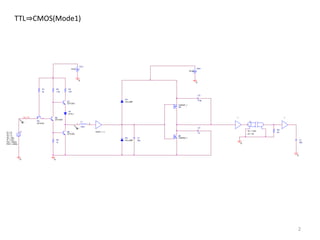
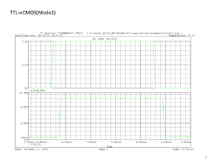
This document models the device behavior of a MC14504B integrated circuit using PSpice software. It contains 6 sections that model the circuit with different configurations: 1) TTL to CMOS mode 1 2) TTL to CMOS mode 1 (continued) 3) CMOS to CMOS mode 0 with 5V VCC and 10V VDD 4) CMOS to CMOS mode 0 with 5V VCC and 10V VDD (continued) 5) CMOS to CMOS mode 0 with 10V VCC and 5V VDD 6) CMOS to CMOS mode 0 with 10V VCC and 5V VDD (continued)


