Downloaded 41 times
![Applied Thermal Engineering 24 (2004) 865–872
www.elsevier.com/locate/apthermeng
Development of no valve solar ice maker
a,*
M. Li , C.J. Sun b, R.Z. Wang b, W.D. Cai a
a
School of Physics and Electronic Information, Yunnan Normal University, Kunming 650092, PR China
b
Institute of Refrigeration and Cryogenics, Shanghai Jiao Tong University, Shanghai 200030, PR China
Received 20 February 2003; accepted 5 October 2003
Abstract
A no valve, flat plate solar ice maker is developed on the basis of previous research achievements of a
large number experiments and theory analysis. There are no valves and measure gauges installed on this
advanced device, also no moving parts on this device, activated carbon and methanol is used as working
pairs for this no valve solar ice maker. Experimental results under both indoor and outdoor showed that
each subsystem, such as adsorbent bed, condenser, evaporator, demonstrated a good performance on
system running processes; this no valve solar ice maker prototype is approached to practical application of
mass production from view of cost and techniques. After the successful study of this no valve solar ice
maker, two new improved economic solar ice makers are fabricated for mass application in China now. All
this will accelerate practical application of solid adsorption refrigeration driven by solar energy.
Ó 2003 Elsevier Ltd. All rights reserved.
Keywords: Solar energy; Ice maker; Advanced development
1. Introduction
The intermittent solid adsorption refrigeration cycle appears to be logical application for solar
cooling, also the activated carbon and methanol seem to be the suitable pair in terms of higher
COP and less expansive than other pairs so far [1,2]. In west China, such as Tibet, a large pro-
portion of people live in rural or remote locations where electricity is presently unavailable or far
from sufficient, also the solar radiation is the most sufficient in those areas. According to statistics
from Tibet, the total sun radiation energy can reach 6000–8000 MJ/m2 per year, and the solar
*
Corresponding author. Tel.: +86-871-5517093; fax: +86-871-5516058.
E-mail address: lmdocyn@public.km.yn.cn (M. Li).
1359-4311/$ - see front matter Ó 2003 Elsevier Ltd. All rights reserved.
doi:10.1016/j.applthermaleng.2003.10.002](https://image.slidesharecdn.com/developmentofnovalvesolaricemaker-121029012901-phpapp01/85/Development-of-no_valve_solar_ice_maker-1-320.jpg)
![866 M. Li et al. / Applied Thermal Engineering 24 (2004) 865–872
radiation hours can be about to 1500–3400 h per year. Hence, solar energy resource can be ef-
fectively used for solar cooling in food and drugs preservation.
Our previous work on solar ice maker has demonstrated the feasibility of the system [3]. The
adsorbent bed was composed in two flat plate collectors, with a total surface area of 1.5 m2 ,
activated carbon and methanol was used as working pair. Each subsystem, such as adsorbent bed,
condenser, evaporator was connected with valve for ideal operation; also thermocouples and
pressure gauges were installed within each subsystem for measuring temperature and pressure
parameters of that solar ice maker. The indoor experiments with quartz lamps instead of real solar
radiation showed that that solar ice maker can produce 7–10 kg ice when the total insolation
accepted by 1.5 m2 collector was 28–30 MJ. However experiments were not conducted outdoor
under real solar conditions. On the basis of successful experiments, a heat and mass transfer
model of solar flat plate ice maker was established [4], and the effects of solar collector and en-
vironment on the performance of a solar powered solid adsorption refrigerator was analyzed
using this model [5]. Above mentioned experience has helped us in designing a no valve solar ice
maker which was tested for the performance in real solar radiation condition. In this paper, we
focus on the design of no valve solar solid adsorption ice maker, also the typical performance of
the no valve solar ice maker valve was given according to the experiments both under indoor and
outdoor conditions.
2. Working principle of the no valve solar ice maker
Fig. 1 shows schematic layout of a no valve solar flat plate ice maker. The solar ice maker
consists of a adsorbent bed (2), a condenser (5), an evaporator (7), water tank (8), insulation box
(9) as well as connecting pipes. For this system, there are no any reservoirs, connecting valves and
throttling valve, the structure of the system is very simple. The working principle of this no valve
solar ice maker is described as follows.
On a sunny day, the adsorbent bed absorbs solar radiation energy, which raises the temperature
of adsorbent bed as well as the pressure of refrigerant in adsorbent bed. When the temperature of
Fig. 1. The sketch structure of the no valve solar ice maker: (1) cover plate, (2) adsorbent bed, (3) insulation materials,
(4) ice frame, (5) condenser, (6) connecting pipe, (7) evaporator, (8) water tank, (9) insulation box.](https://image.slidesharecdn.com/developmentofnovalvesolaricemaker-121029012901-phpapp01/85/Development-of-no_valve_solar_ice_maker-2-320.jpg)
![M. Li et al. / Applied Thermal Engineering 24 (2004) 865–872 867
adsorbent reaches the desorption temperature, the refrigerant begins to evaporate and desorb
from the bed. The desorbed refrigerant vapor will be condensed into liquid via the condenser and
flows into the evaporator directly; this desorption process lasts until the temperature of adsorbent
reaches the maximum desorption temperature. During night, when the temperature of the ad-
sorbent bed reduces, the refrigerant vapor from the evaporator gets adsorbent back in the bed.
During this adsorption process, the cooling effect is released from refrigerant evaporation, and the
ice is formed in the water tank placed inside thermal insulated water box.
In general, the performance of solar ice maker are represented in terms of Qref (or ice mass
gotten in water tank) and the performance efficiency COPsolar . They can be expressed as follows:
Qref ¼ DxMa Le ð1Þ
Dx ¼ xconc À xdil ð2Þ
where xconc is the adsorption capacity before desorption, xdil is the adsorption capacity after de-
sorption, Ma is the mass of adsorbent inside adsorbent bed, Le is the latent heat of vaporization.
Qref À Qcc
COPsolar ¼ R ð3Þ
iðtÞ dt
RT
where Qcc ¼ Tce Ma DxCpl dT is the energy used to cool down the refrigerant liquid from con-
R
densing temperature Tc to evaporation temperature Te . iðtÞ dt is the total radiant energy absorbed
by the collector during one day operation.
3. Construction of no valve solar ice maker
3.1. Adsorbent bed
Adsorbent bed is the most important part of the solar ice maker and hence the performance of
the solar ice maker depends highly on the characteristics of the adsorbent bed. Generally
speaking, a good adsorbent bed must have good heat and mass transfer. Recent research showed
that the aluminum alloy have a stronger catalytic effect on the decomposition reaction under the
solar adsorption refrigeration [6], therefore stainless steel are used as adsorbent heat transfer
metal instead of aluminum alloy although stainless steel has poor heat transfer ability than that of
aluminum alloy. The adsorbent bed is made of flat plate stainless steel box, having surface area
1 m2 , also 19 kg adsorbent (activated carbon produced by Hainan province, China) is charged and
sealed inside the steel plate box, then selective coating is covered on top surface of the steel plate
box. Finally the steel plate box is placed behind two sheets of fibre plastic plates in a thermal
insulated case. The permeability of the fibre plastic plate for solar radiation is about 0.92, which is
higher than that of glass. In order to guarantee better heat transfer between the front side and the
adsorbent, many fins (also made of stainless steel) are placed inside the adsorbent bed box in
contact with the front side and the activated carbon. The distance between these fins is approx-
imately 0.1 m. The thickness of the adsorbent layer is about 0.04 m, the total weight of stainless
steel metal is about 20 kg, those parameters mentioned above are obtained according to both
previous experimental results and optimized calculation.](https://image.slidesharecdn.com/developmentofnovalvesolaricemaker-121029012901-phpapp01/85/Development-of-no_valve_solar_ice_maker-3-320.jpg)
![868 M. Li et al. / Applied Thermal Engineering 24 (2004) 865–872
Fig. 2. Adsorbent bed (mm): (1) activated carbon, (2) stainless steel plate, (3) heat transfer fins, (4) metallic screen,
(5) supporting bar.
In order to improve the transfer of methanol vapor through the activated carbon layer, a false
bottom (0.01 m thick in the radial distance) is included in the rear side of the adsorbent bed as
mentioned by Pons and Guillemiont [2]. As this ‘‘false bottom’’ is completely open to the cir-
culation of vapors, it permits an uniform distribution of methanol in the adsorbent. The schematic
diagram of the adsorbent bed is shown in Fig. 2.
3.2. Condenser and evaporator
During the process of desorption of methanol, a well designed condenser is needed to reject the
desorption heat. To fulfil this condition, the £18 mm copper tubes with £36 mm external alu-
minum fins are used as condenser, the total heat transfer areas of the condenser is about 4.5 m2 .
The schematic diagram of the condenser is shown in Fig. 3.
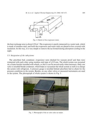
The evaporator must have sufficient volume to collect all the condensed methanol. In order to
enhance the heat transfer effect, the heat exchange surface is designed as a series of four trape-
zoidal cells shown in Fig. 4, the dimension of the evaporator is 220 mm · 320 mm · 100 mm and
Fig. 3. Structure of condenser (mm).](https://image.slidesharecdn.com/developmentofnovalvesolaricemaker-121029012901-phpapp01/85/Development-of-no_valve_solar_ice_maker-4-320.jpg)
![M. Li et al. / Applied Thermal Engineering 24 (2004) 865–872 871
Table 2
Some typical research results of solar ice maker
Research group Working pairs Collector areas Solar radiation COP Ice mass per Reference
(m2 ) intensity per day (kg)
day (MJ/m2 )
Pons and Activated 6 22 0.12 30–35 [2]
Guillemiont carbon–methanol 19 0.10
Headley et al. Activated 2 25 0.02 1.0 [7]
carbon–methanol
Iloeje CaCI2 and NH3 1.41 12 0.1 1.0 kg/m2 [8]
Boubakri et al. Activated 1.0 19.5 0.12 4.0 [9]
carbon–methanol
Tan et al. Activated 1.1 22 0.09 3 kg [10]
carbon–methanol
Lin et al. CaCI2 and NH3 1.6 20 0.08 3.2 kg [11]
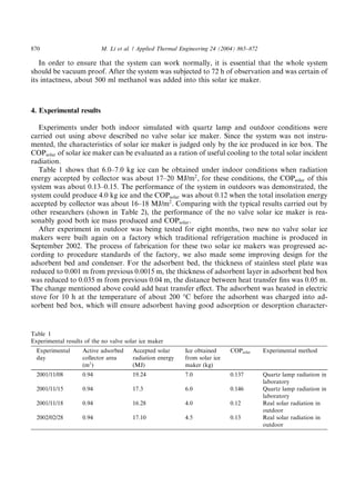
istics. The thickness of insulation materials was added to 0.05 m for keeping off heating loss of
adsorbent bed when collector accepts solar radiation. For condenser, eight copper tubes, each
tube having 0.4 m length and diameter of £18 mm, with aluminum fins which has thickness of
0.0001 m and about total heat transfer areas of 6.0 m2 are used. The effective collector areas of the
improved no valve solar ice maker is about 1 m2 . The photograph of the improved no valve solar
ice maker is shown in Fig. 6. The satisfying experimental results were obtained again for these two
new improved no valve solar ice makers. The ice mass produced by each new improved no valve
solar maker is about 5.0 kg per day, the COPsolar is about 0.12–0.14 when the solar ice maker
receives solar radiation about 18–22 MJ/m2 .
Fig. 6. Photograph of the improved no valve solar ice maker.](https://image.slidesharecdn.com/developmentofnovalvesolaricemaker-121029012901-phpapp01/85/Development-of-no_valve_solar_ice_maker-7-320.jpg)
![872 M. Li et al. / Applied Thermal Engineering 24 (2004) 865–872
5. Conclusions
A no valve solar ice maker was built on the basis of the previous research achievements. The
characteristics of the no valve solar ice maker appears to be reasonable application in west of
China, where the solar radiation resource is abundant while the availability of electricity is rel-
atively less in most villages. The price of the no valve solar ice maker can be expected no more
than RMB 2000 yun (about US $250) for per solar ice maker with 1 m2 collector. This solar ice
maker can produce about ice of 4–5 kg each sunny day under the condition of about 18–22 MJ/m2
solar insolation, the no valve solar ice maker is expected to be economical in west of China in near
future.
Acknowledgements
This work was supported by the National Key Fundamental Research Program under the
contract no. G2000026309; the Natural Science Foundation of Educational Ministry of Yunnan
Province, China.
References
[1] R.E. Critoph, Performance limitations of adsorption cycles for solar cooling, Solar Energy 41 (1988) 21–31.
[2] M. Pons, J.J. Guillemiont, Design of an experimental solar-powered, solid-adsorption ice maker, Trans. ASME,
J. Solar Energy Eng. 108 (4) (1986) 332–337.
[3] M. Li, R.Z. Wang, Y.X. Xu, J.Y. Wu, A.O. Dieng, Experimental study on dynamic performance analysis of a flat-
plate solar solid-adsorption refrigeration for ice maker, Renew. Energy 27 (2002) 211–221.
[4] M. Li, R.Z. Wang, Heat and mass transfer in a flat plate solar solid adsorption, Renew. Energy 28 (2003) 613–622.
[5] M. Li, R.Z. Wang, A study of the effects of collector and environment parameters on the performance of a solar
powered solid adsorption refrigerator, Renew. Energy 27 (2002) 369–382.
[6] E.J. Hu, A study of thermal decomposition of methanol in solar powered adsorption refrigeration systems, Solar
Energy 62 (1998) 325–329.
[7] O.S. Headley, A.F. Kohdiwala, I.A. Doom, Charcoal–methanol adsorption refrigerator powered by a compound
parabolic concentrating solar collect, Solar Energy 53 (2) (1994) 191–197.
[8] O.C. Iloeje, Quantitative comparison of treated CaCl2 absorbent for solar refrigeration, Solar Energy 37 (4) (1986)
253–260.
[9] J.J. Boubakri, J.J. Guillemiont, Meunier, Adsorptive solar powered ice-maker: experiments and model, Solar
Energy 69 (2000) 249–263.
[10] Y.-k. Tan, Y. Feng, N.-y. Cui, Study of solar powered adsorption ice maker, Acta Energiae Solaris Sin. 13 (3)
(1992) 255–258.
[11] G.-p. Lin, X.-g. Yuan, Z.-g. Mei, Solar-powered solid absorption ice maker, Acta Energiae Solaris Sin. 14 (2)
(1993) 101–104.](https://image.slidesharecdn.com/developmentofnovalvesolaricemaker-121029012901-phpapp01/85/Development-of-no_valve_solar_ice_maker-8-320.jpg)

1. A no valve solar ice maker is developed that uses activated carbon and methanol as working pairs without valves or moving parts. 2. Experimental results showed good performance of the adsorbent bed, condenser, and evaporator during system operation under indoor and outdoor conditions. 3. The design of the no valve solar ice maker is simplified compared to previous designs, making it more practical for mass production and application based on cost and techniques.


