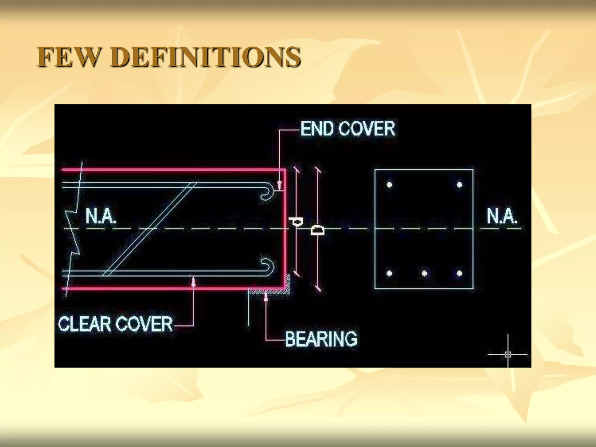
DESIGN OF
SINGLY REINFORCED
BEAM
.
BEAM:-
A Beam is any structural member which resists
load mainly by bending. Therefore it is also
called flexural member. Beam may be singly
reinforced or doubly reinforced. When steel is
provided only in tensile zone (i.e. below neutral
axis) is called singly reinforced beam, but when
steel is provided in tension zone as well as
compression zone is called doubly reinforced
beam.
The aim of design is:
To decide the size (dimensions) of the member
and the amount of reinforcement required.
To check whether the adopted section will
perform safely and satisfactorily during the life
time of the structure.
FEW DEFINITIONS
OVER ALL DEPTH :-
THE NORMAL DISTANCE FROM THE TOP EDGE
OF THE BEAM TO THE BOTTOM EDGE OF THE
BEAM IS CALLED OVER ALL DEPTH. IT IS
DENOTED BY ‘D’.
EFFECTIVE DEPTH:-
THE NORMAL DISTANCE FROM THE TOP EDGE
OF BEAM TO THE CENTRE OF TENSILE
REINFORCEMENT IS CALLED EFFECTIVE
DEPTH. IT IS DENOTED BY ‘d’.
CLEAR COVER:-
THE DISTANCE BETWEEN THE BOTTOM OF
THE BARS AND BOTTOM MOST THE EDGE OF
THE BEAM IS CALLED CLEAR COVER.
CLEAR COVER = 25mm OR DIA OF MAIN BAR,
(WHICH EVER IS GREATER).
EFFECTIVE COVER:-
THE DISTANCE BETWEEN CENTRE OF TENSILE
REINFORCEMENT AND THE BOTTOM EDGE OF
THE BEAM IS CALLED EFFECTIVE COVER.
EFFECTIVE COVER = CLEAR COVER + ½ DIA
OF BAR.
END COVER:-
END COVER = 2XDIA OF BAR OR 25mm (WHICH
EVER IS GREATER)
NEUTRAL AXIS:- THE LAYER / LAMINA WHERE
NO STRESS EXIST IS KNOWN AS NEUTRAL AXIS.
IT DIVIDES THE BEAM SECTION INTO TWO
ZONES, COMPRESION ZONE ABOVE THE
NETURAL AXIS & TENSION ZONE BELOW THE
NEUTRAL AXIS.
DEPTH OF NETURAL AXIS:- THE NORMAL
DISTANCE BETWEEN THE TOP EDGE OF THE
BEAM & NEUTRAL AXIS IS CALLED DEPTH OF
NETURAL AXIS. IT IS DENOTED BY ‘n’.
LEVER ARM:- THE DISTANCE BETWEEN THE
RESULTANT COMPRESSIVE FORCE (C) AND
TENSILE FORCE (T) IS KNOWN AS LEVER ARM. IT
IS DENOTED BY ‘z’. THE TOTAL COMPRESSIVE
FORCE (C) IN CONCRETE ACT AT THE C.G. OF
COMPRESSIVE STRESS DIAGRAM i.e. n/3 FROM
THE COMPRESSION EDGE. THE TOTAL TENSILE
FORCE (T) ACTS AT C.G. OF THE
REINFORCEMENT.
LEVER ARM = d-n/3
TENSILE REINFORCEMENT:-
THE REINFORCEMENT PROVIDED TENSILE
ZONE IS CALLED TENSILE REINFORCEMENT.
IT IS DENOTED BY Ast.
COMPRESSION REINFORCEMENT :-
THE REINFORCEMENT PROVIDED
COMPRESSION ZONEIS CALLED
COMPRESSION REINFORCEMENT. IT IS
DENOTED BY Asc
TYPES OF BEAM SECTION:- THE BEAM
SECTION CAN BE OF THE FOLLOWING TYPES:
1.BALANCED SECTION
2.UNBALNCED SECTION
(a) UNDER- REINFORCED SECTION
(b) OVER-REINFORCED SECTION
1.BALANCED SECTION:- A SECTION IS
KNOWN AS BALANCED SECTION IN WHICH
THE COMPRESSIVE STREE IN CONCRETE (IN
COMPRESSIVE ZONES) AND TENSILE STRESS
IN STEEL WILL BOTH REACH THE MAXIMUM
PERMISSIBLE VALUES SIMULTANEOUSLY.
THE NEUTRAL AXIS OF BALANCED (OR
CRITICAL) SECTION IS KNOWN AS CRITICAL
NEUTRAL AXIS (nc). THE AREA OF STEEL
PROVIDED AS ECONOMICAL AREA OF STEEL.
REINFORCED CONCRETE SECTIONS ARE
DESIGNED AS BALANCED SECTIONS.
2. UNBALNCED SECTION:-THIS IS A SECTION IN
WHICH THE QUANTITY OF STEEL PROVIDED IS
DIFFERENT FROM WHAT IS REQUIRED FOR THE
BALANCED SECTION.
UNBALANCED SECTIONS MAY BE OF THE
FOLLOWING TWO TYPES:
(a) UNDER-REINFORCED SECTION
(b) OVER-REINFORCED SECTION
(a)UNDER-REINFORCED SECTION:- IF THE AREA
OF STEEL PROVIDED IS LESS THAN THAT REQUIRED
FOR BALANCED SECTION, IT IS KNOWN AS UNDER-
REINFORCED SECTION. DUE TO LESS
REINFORCEMENT THE POSITION OF ACTUAL
NEUTRAL AXIS (n) WILL SHIFT ABOVE THE CRITICAL
NEUTRAL AXIS (nc)i.e. n< nc. IN UNDER-REINFORCED
SECTION STEEL IS FULLY STRESSED AND CONCRETE
IS UNDER STRESSED (i.e. SOME CONCRETE REMAINS
UN-UTILISED). STEEL BEING DUCTILE, TAKES SOME
TIME TO BREAK. THIS GIVES SUFFICIENT WARNING
BEFORE THE FINAL COLLAPSE OF THE STRUCTURE.
FOR THIS REASON AND FROM ECONOMY POINT OF
VIEW THE UNDER-REINFORCED SECTIONS ARE
DESIGNED.
(b) OVER-REINFORCED SECTION:- IF THE AREA
OF STEEL PROVIDED IS MORE THAN THAT
REQUIRED FOR A BALANCED SECTION, IT IS
KNOWN AS OVER-REINFORCED SECTION. AS THE
AREA OF STEEL PROVIDED IS MORE, THE
POSITION OF N.A. WILL SHIFT TOWARDS STEEL,
THEREFORE ACTUAL AXIS (n) IS BELOW THE
CRITICAL NEUTRAL AXIS (nc)i.e. n > nc. IN THIS
SECTION CONCRETE IS FULLY STRESSED AND
STEEL IS UNDER STRESSED. UNDER SUCH
CONDITIONS, THE BEAM WILL FAIL INITIALLY DUE
TO OVER STRESS IN THE CONCRETE. CONCRETE
BEING BRITTLE, THIS HAPPENS SUDDENLY AND
EXPLOSIVELY WITHOUT ANY WARNING.
Basic rules for design of beam:-
1. Effective span:- In the case of simply supported
beam the effective length,
l = i. Distance between the centre of support
ii. Clear span + eff. Depth
eff. Span = least of i. & ii.
2. Effective depth:- The normal distance from the
top edge of beam to the centre of tensile
reinforcement is called effective depth. It is denoted
by ‘d’.
d= D- effect. Cover
where D= over all depth
3. Bearing :- Bearings of beams on brick walls may
be taken as follow:
 Up to 3.5 m span, bearing = 200mm
 Up to 5.5 m span, bearing =300mm
 Up to 7.0 m span, bearing =400mm
4. Deflection control:- The vertical deflection limits
assumed to be satisfied if (a) For span up to 10m
Span / eff. Depth = 20
(For simply supported beam)
Span / eff. Depth = 7
(For cantilever beam)
(b) For span above 10m, the value in (a) should
be multiplied by 10/span (m), except for
cantilever for which the deflection calculations
should be made.
(c) Depending upon the area and type of steel the
value of (a&b) modified as per modification
factor.
5. Reinforcement :-
(a) Minimum reinforcement:- The minimum area
of tensile reinforcement shall not be less than that
given by the following:
Ast = 0.85 bd / fy
(b)Maximum reinforcement:- The maximum area of
tensile reinforcement shall not be more than 0.4bD
(c)Spacing of reinforcement bars:-
i. The horizontal distance between to parallel main bars
shall not be less than the greatest of the following:
 Diameter of the bar if the bars are of same diameter.
 Diameter of the larger bar if the diameter are unequal.
 5mm more than the nominal maximum size of coarse
aggregate.
ii. When the bars are in vertical lines and the minimum
vertical distance between the bars shall be greater of the
following:
 15mm.
 2/3rd of nominal maximum size of aggregate.
 Maximum diameter of the bar.
6. Nominal cover to reinforcement :- The Nominal
cover is provided in R.C.C. design:
 To protect the reinforcement against corrosion.
 To provide cover against fire.
 To develop the sufficient bond strength along the
surface area of the steel bar.
As per IS 456-2000, the value of nominal cover
to meet durability requirements as follow:-
Exposure
conditions
Nominal
cover(mm)
Not less than
Mild
Moderate
Severe
Very severe
Extreme
20
30
45
50
75
Procedure for Design of Singly Reinforced
Beam by Working Stress Method
Given :
(i) Span of the beam (l)
(ii) Loads on the beam
(iii)Materials-Grade of Concrete and type of steel.
1. Calculate design constants for the given materials
(k, j and R)
k = m σcbc / m σcbc + σst
where k is coefficient of depth of Neutral Axis
j = 1- k/3
where j is coefficient of lever arm.
R= 1/2 σcbc kj
where R is the resisting moment factor.
2. Assume dimension of beam:
d = Span/10 to Span/8
Effective cover = 40mm to 50mm
b = D/2 to 2/3D
3. Calculate the effective span (l) of the beam.
4. Calculate the self weight (dead load) of the beam.
Self weight = D x b x 25000 N/m
5. Calculate the total Load & maximum bending
moment for the beam.
Total load (w) = live load + dead load
Maximum bending moment, M = wl2 / 8 at the centre
of beam for simply supported beam.
M = wl2 / 2 at the support
of beam for cantilever beam.
6. Find the minimum effective depth
M = Mr
= Rbd2
dreqd. = √ M / R.b
7. Compare dreqd. With assumed depth value.
(i) If it is less than the assumed d, then assumption is
correct.
(ii) If dreqd. is more than assumed d, then revise the
depth value and repeat steps 4, 5 & 6.
8. Calculate the area of steel required (Ast).
Ast = M / σst jd
Selecting the suitable diameter of bar calculate the
number of bars required
Area of one bar = π/4 x φ2 = Aφ
No. of bars required = Ast /Aφ
9. Calculate minimum area of steel (AS) required
by the relation:
AS = 0.85 bd / fy
Calculate maximum area of steel by the area
relation:
Maximum area of steel = 0.04bD
Check that the actual ASt provided is more than
minimum and less than maximum requirements.
10. Check for shear and design shear reinforcement.
11. Check for development length.
12. Check for depth of beam from deflection.
13. Write summary of design and draw a neat sketch.
design-of-singly-reinforced-beam.ppt

design-of-singly-reinforced-beam.ppt

  • 1.
  • 2.
    BEAM:- A Beam isany structural member which resists load mainly by bending. Therefore it is also called flexural member. Beam may be singly reinforced or doubly reinforced. When steel is provided only in tensile zone (i.e. below neutral axis) is called singly reinforced beam, but when steel is provided in tension zone as well as compression zone is called doubly reinforced beam.
  • 3.
    The aim ofdesign is: To decide the size (dimensions) of the member and the amount of reinforcement required. To check whether the adopted section will perform safely and satisfactorily during the life time of the structure.
  • 4.
  • 5.
    OVER ALL DEPTH:- THE NORMAL DISTANCE FROM THE TOP EDGE OF THE BEAM TO THE BOTTOM EDGE OF THE BEAM IS CALLED OVER ALL DEPTH. IT IS DENOTED BY ‘D’. EFFECTIVE DEPTH:- THE NORMAL DISTANCE FROM THE TOP EDGE OF BEAM TO THE CENTRE OF TENSILE REINFORCEMENT IS CALLED EFFECTIVE DEPTH. IT IS DENOTED BY ‘d’.
  • 6.
    CLEAR COVER:- THE DISTANCEBETWEEN THE BOTTOM OF THE BARS AND BOTTOM MOST THE EDGE OF THE BEAM IS CALLED CLEAR COVER. CLEAR COVER = 25mm OR DIA OF MAIN BAR, (WHICH EVER IS GREATER). EFFECTIVE COVER:- THE DISTANCE BETWEEN CENTRE OF TENSILE REINFORCEMENT AND THE BOTTOM EDGE OF THE BEAM IS CALLED EFFECTIVE COVER. EFFECTIVE COVER = CLEAR COVER + ½ DIA OF BAR.
  • 7.
    END COVER:- END COVER= 2XDIA OF BAR OR 25mm (WHICH EVER IS GREATER) NEUTRAL AXIS:- THE LAYER / LAMINA WHERE NO STRESS EXIST IS KNOWN AS NEUTRAL AXIS. IT DIVIDES THE BEAM SECTION INTO TWO ZONES, COMPRESION ZONE ABOVE THE NETURAL AXIS & TENSION ZONE BELOW THE NEUTRAL AXIS.
  • 8.
    DEPTH OF NETURALAXIS:- THE NORMAL DISTANCE BETWEEN THE TOP EDGE OF THE BEAM & NEUTRAL AXIS IS CALLED DEPTH OF NETURAL AXIS. IT IS DENOTED BY ‘n’. LEVER ARM:- THE DISTANCE BETWEEN THE RESULTANT COMPRESSIVE FORCE (C) AND TENSILE FORCE (T) IS KNOWN AS LEVER ARM. IT IS DENOTED BY ‘z’. THE TOTAL COMPRESSIVE FORCE (C) IN CONCRETE ACT AT THE C.G. OF COMPRESSIVE STRESS DIAGRAM i.e. n/3 FROM THE COMPRESSION EDGE. THE TOTAL TENSILE FORCE (T) ACTS AT C.G. OF THE REINFORCEMENT. LEVER ARM = d-n/3
  • 9.
    TENSILE REINFORCEMENT:- THE REINFORCEMENTPROVIDED TENSILE ZONE IS CALLED TENSILE REINFORCEMENT. IT IS DENOTED BY Ast. COMPRESSION REINFORCEMENT :- THE REINFORCEMENT PROVIDED COMPRESSION ZONEIS CALLED COMPRESSION REINFORCEMENT. IT IS DENOTED BY Asc
  • 10.
    TYPES OF BEAMSECTION:- THE BEAM SECTION CAN BE OF THE FOLLOWING TYPES: 1.BALANCED SECTION 2.UNBALNCED SECTION (a) UNDER- REINFORCED SECTION (b) OVER-REINFORCED SECTION 1.BALANCED SECTION:- A SECTION IS KNOWN AS BALANCED SECTION IN WHICH THE COMPRESSIVE STREE IN CONCRETE (IN COMPRESSIVE ZONES) AND TENSILE STRESS IN STEEL WILL BOTH REACH THE MAXIMUM PERMISSIBLE VALUES SIMULTANEOUSLY.
  • 11.
    THE NEUTRAL AXISOF BALANCED (OR CRITICAL) SECTION IS KNOWN AS CRITICAL NEUTRAL AXIS (nc). THE AREA OF STEEL PROVIDED AS ECONOMICAL AREA OF STEEL. REINFORCED CONCRETE SECTIONS ARE DESIGNED AS BALANCED SECTIONS. 2. UNBALNCED SECTION:-THIS IS A SECTION IN WHICH THE QUANTITY OF STEEL PROVIDED IS DIFFERENT FROM WHAT IS REQUIRED FOR THE BALANCED SECTION. UNBALANCED SECTIONS MAY BE OF THE FOLLOWING TWO TYPES: (a) UNDER-REINFORCED SECTION (b) OVER-REINFORCED SECTION
  • 12.
    (a)UNDER-REINFORCED SECTION:- IFTHE AREA OF STEEL PROVIDED IS LESS THAN THAT REQUIRED FOR BALANCED SECTION, IT IS KNOWN AS UNDER- REINFORCED SECTION. DUE TO LESS REINFORCEMENT THE POSITION OF ACTUAL NEUTRAL AXIS (n) WILL SHIFT ABOVE THE CRITICAL NEUTRAL AXIS (nc)i.e. n< nc. IN UNDER-REINFORCED SECTION STEEL IS FULLY STRESSED AND CONCRETE IS UNDER STRESSED (i.e. SOME CONCRETE REMAINS UN-UTILISED). STEEL BEING DUCTILE, TAKES SOME TIME TO BREAK. THIS GIVES SUFFICIENT WARNING BEFORE THE FINAL COLLAPSE OF THE STRUCTURE. FOR THIS REASON AND FROM ECONOMY POINT OF VIEW THE UNDER-REINFORCED SECTIONS ARE DESIGNED.
  • 13.
    (b) OVER-REINFORCED SECTION:-IF THE AREA OF STEEL PROVIDED IS MORE THAN THAT REQUIRED FOR A BALANCED SECTION, IT IS KNOWN AS OVER-REINFORCED SECTION. AS THE AREA OF STEEL PROVIDED IS MORE, THE POSITION OF N.A. WILL SHIFT TOWARDS STEEL, THEREFORE ACTUAL AXIS (n) IS BELOW THE CRITICAL NEUTRAL AXIS (nc)i.e. n > nc. IN THIS SECTION CONCRETE IS FULLY STRESSED AND STEEL IS UNDER STRESSED. UNDER SUCH CONDITIONS, THE BEAM WILL FAIL INITIALLY DUE TO OVER STRESS IN THE CONCRETE. CONCRETE BEING BRITTLE, THIS HAPPENS SUDDENLY AND EXPLOSIVELY WITHOUT ANY WARNING.
  • 14.
    Basic rules fordesign of beam:- 1. Effective span:- In the case of simply supported beam the effective length, l = i. Distance between the centre of support ii. Clear span + eff. Depth eff. Span = least of i. & ii. 2. Effective depth:- The normal distance from the top edge of beam to the centre of tensile reinforcement is called effective depth. It is denoted by ‘d’. d= D- effect. Cover where D= over all depth
  • 15.
    3. Bearing :-Bearings of beams on brick walls may be taken as follow:  Up to 3.5 m span, bearing = 200mm  Up to 5.5 m span, bearing =300mm  Up to 7.0 m span, bearing =400mm 4. Deflection control:- The vertical deflection limits assumed to be satisfied if (a) For span up to 10m Span / eff. Depth = 20 (For simply supported beam) Span / eff. Depth = 7 (For cantilever beam)
  • 16.
    (b) For spanabove 10m, the value in (a) should be multiplied by 10/span (m), except for cantilever for which the deflection calculations should be made. (c) Depending upon the area and type of steel the value of (a&b) modified as per modification factor. 5. Reinforcement :- (a) Minimum reinforcement:- The minimum area of tensile reinforcement shall not be less than that given by the following: Ast = 0.85 bd / fy
  • 17.
    (b)Maximum reinforcement:- Themaximum area of tensile reinforcement shall not be more than 0.4bD (c)Spacing of reinforcement bars:- i. The horizontal distance between to parallel main bars shall not be less than the greatest of the following:  Diameter of the bar if the bars are of same diameter.  Diameter of the larger bar if the diameter are unequal.  5mm more than the nominal maximum size of coarse aggregate.
  • 18.
    ii. When thebars are in vertical lines and the minimum vertical distance between the bars shall be greater of the following:  15mm.  2/3rd of nominal maximum size of aggregate.  Maximum diameter of the bar. 6. Nominal cover to reinforcement :- The Nominal cover is provided in R.C.C. design:  To protect the reinforcement against corrosion.  To provide cover against fire.  To develop the sufficient bond strength along the surface area of the steel bar.
  • 19.
    As per IS456-2000, the value of nominal cover to meet durability requirements as follow:- Exposure conditions Nominal cover(mm) Not less than Mild Moderate Severe Very severe Extreme 20 30 45 50 75
  • 20.
    Procedure for Designof Singly Reinforced Beam by Working Stress Method Given : (i) Span of the beam (l) (ii) Loads on the beam (iii)Materials-Grade of Concrete and type of steel. 1. Calculate design constants for the given materials (k, j and R) k = m σcbc / m σcbc + σst where k is coefficient of depth of Neutral Axis
  • 21.
    j = 1-k/3 where j is coefficient of lever arm. R= 1/2 σcbc kj where R is the resisting moment factor. 2. Assume dimension of beam: d = Span/10 to Span/8 Effective cover = 40mm to 50mm b = D/2 to 2/3D 3. Calculate the effective span (l) of the beam. 4. Calculate the self weight (dead load) of the beam. Self weight = D x b x 25000 N/m
  • 22.
    5. Calculate thetotal Load & maximum bending moment for the beam. Total load (w) = live load + dead load Maximum bending moment, M = wl2 / 8 at the centre of beam for simply supported beam. M = wl2 / 2 at the support of beam for cantilever beam. 6. Find the minimum effective depth M = Mr = Rbd2 dreqd. = √ M / R.b
  • 23.
    7. Compare dreqd.With assumed depth value. (i) If it is less than the assumed d, then assumption is correct. (ii) If dreqd. is more than assumed d, then revise the depth value and repeat steps 4, 5 & 6. 8. Calculate the area of steel required (Ast). Ast = M / σst jd Selecting the suitable diameter of bar calculate the number of bars required Area of one bar = π/4 x φ2 = Aφ No. of bars required = Ast /Aφ
  • 24.
    9. Calculate minimumarea of steel (AS) required by the relation: AS = 0.85 bd / fy Calculate maximum area of steel by the area relation: Maximum area of steel = 0.04bD Check that the actual ASt provided is more than minimum and less than maximum requirements.
  • 25.
    10. Check forshear and design shear reinforcement. 11. Check for development length. 12. Check for depth of beam from deflection. 13. Write summary of design and draw a neat sketch.