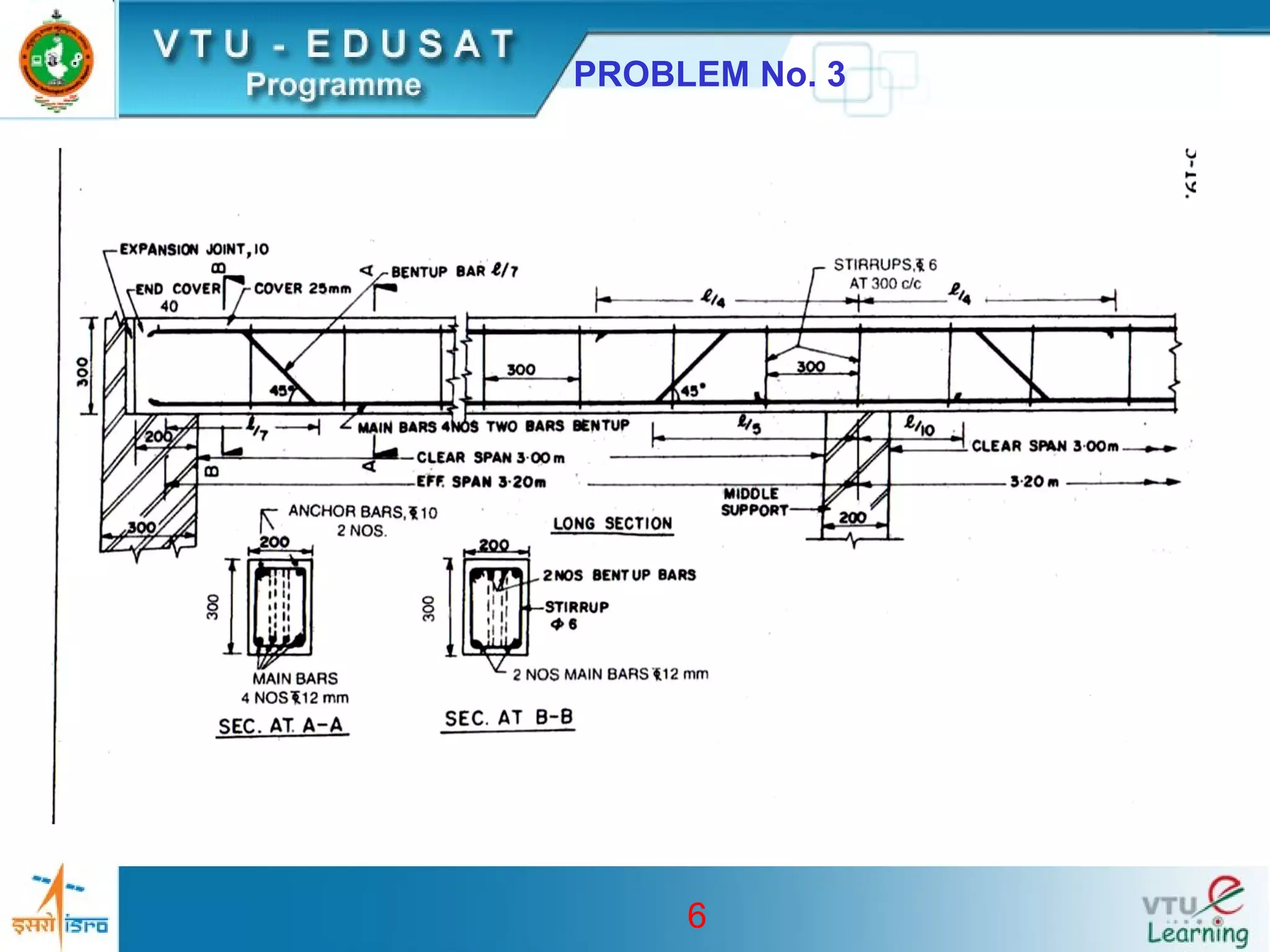
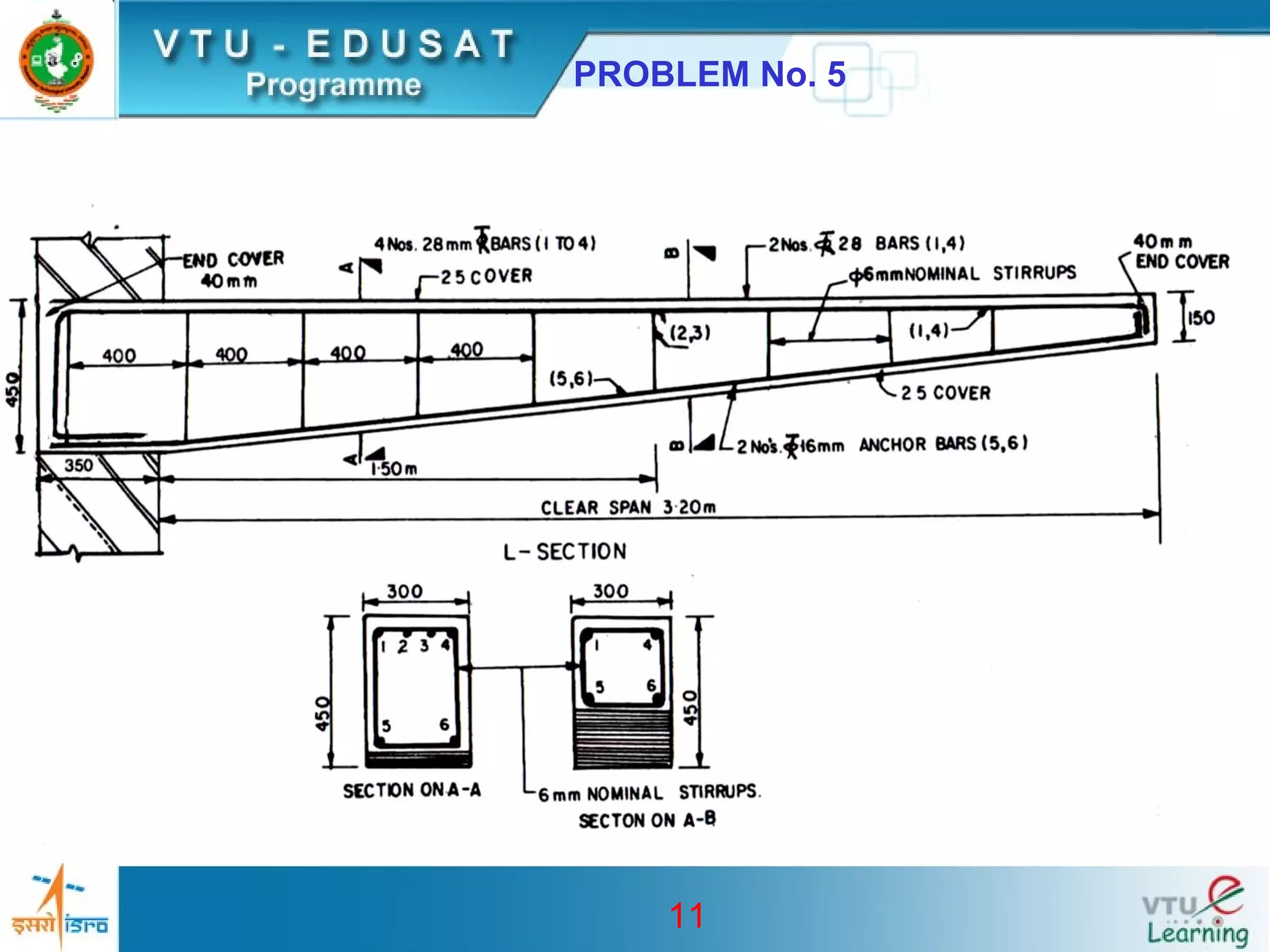
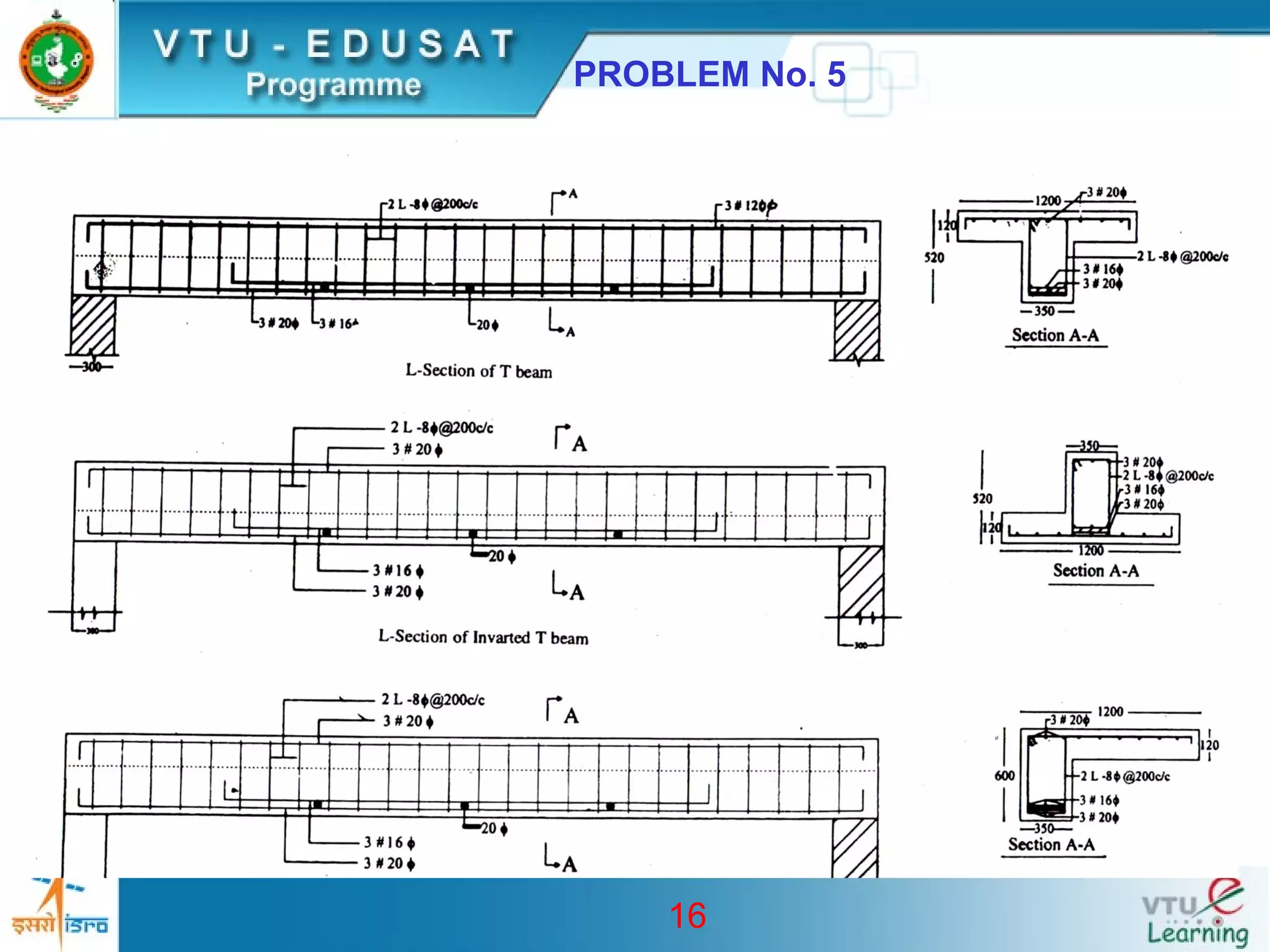
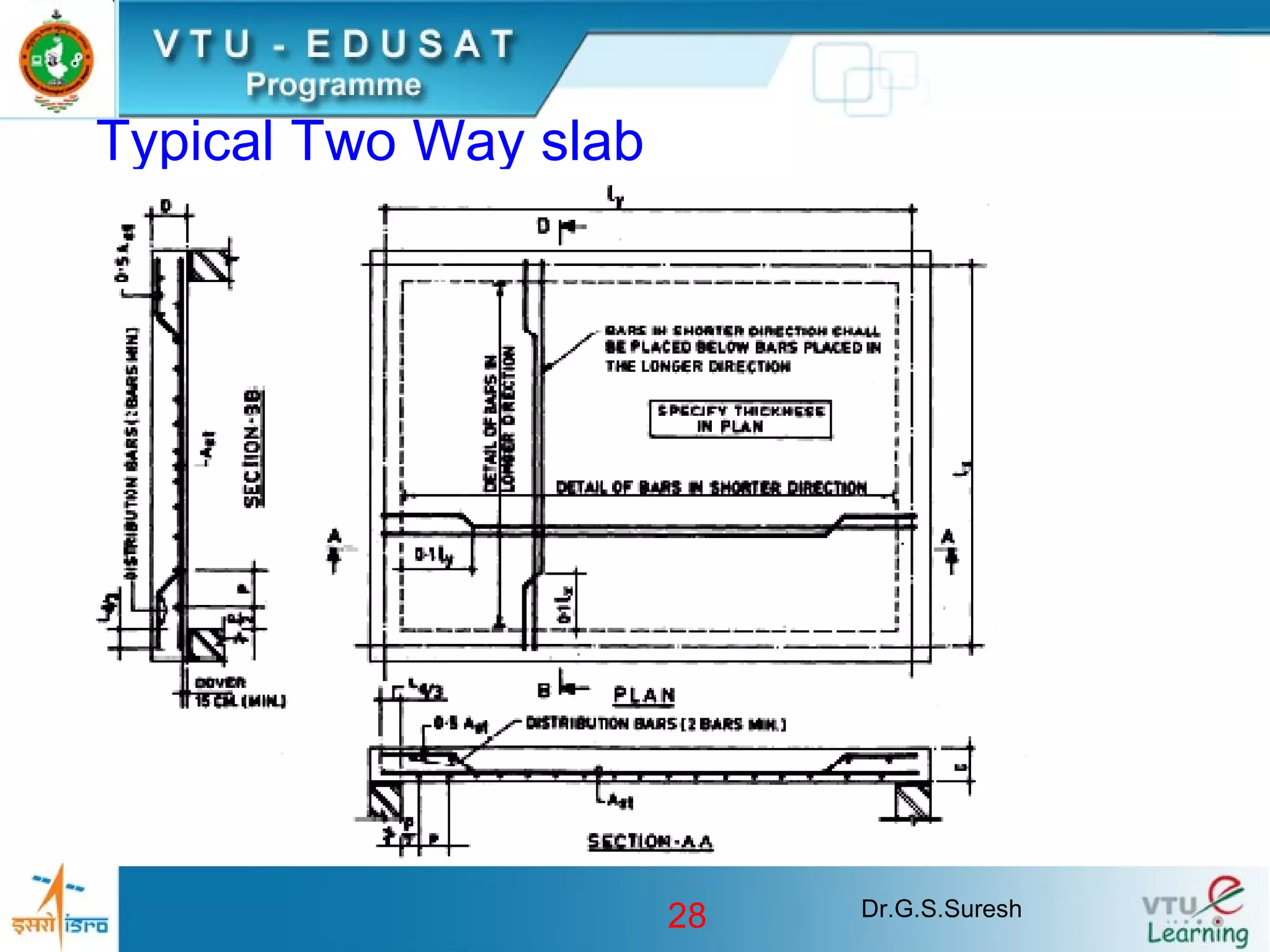
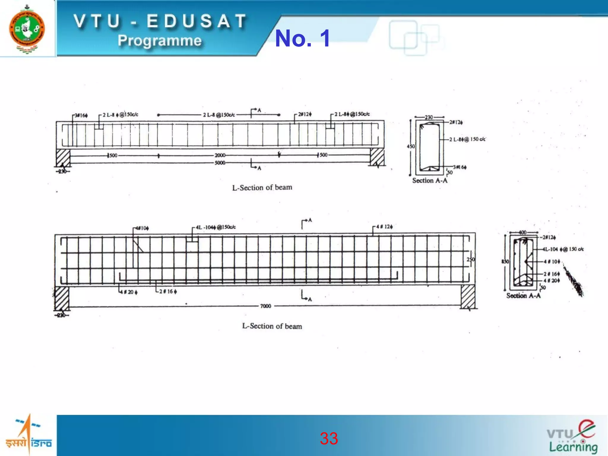
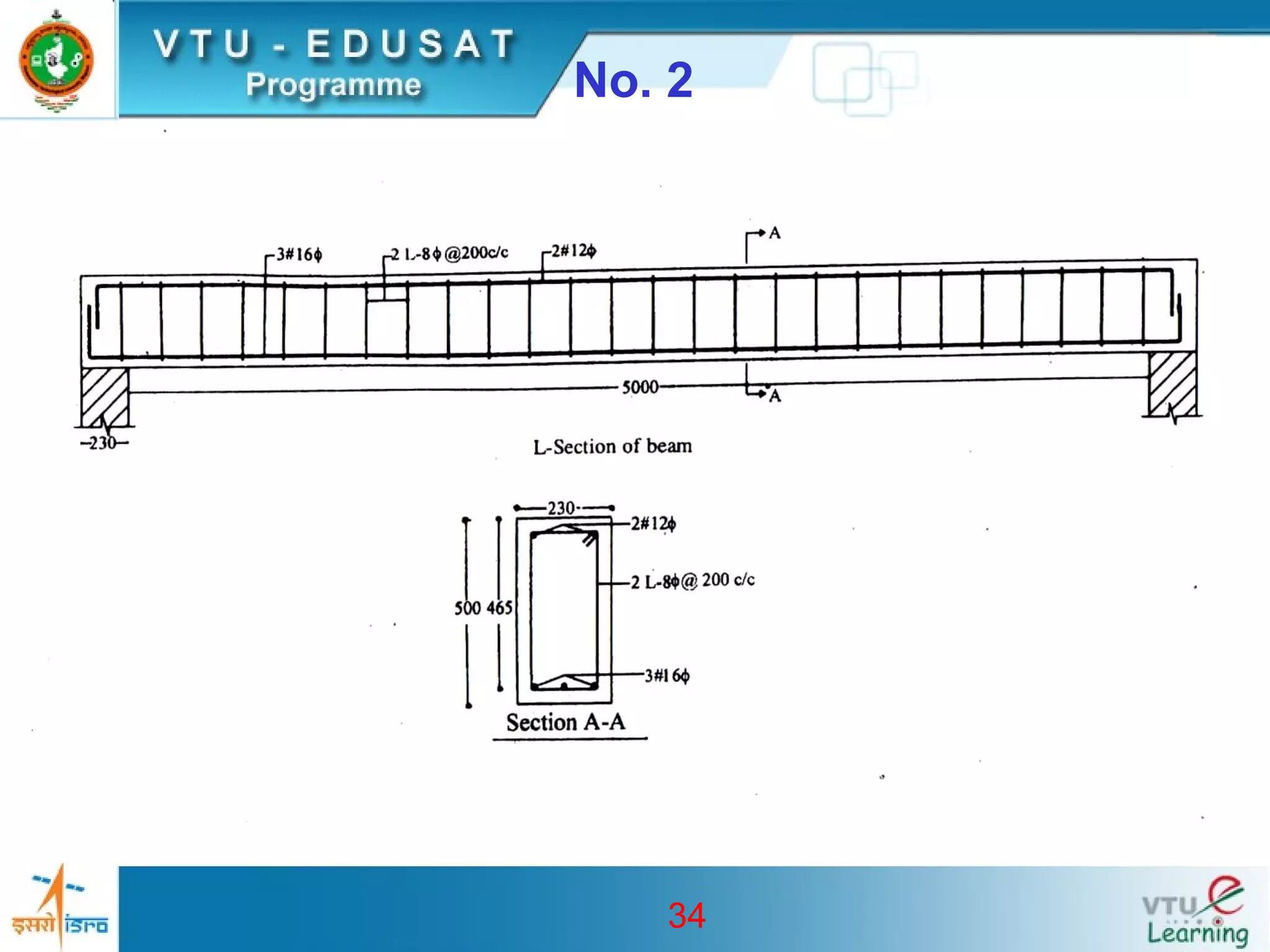
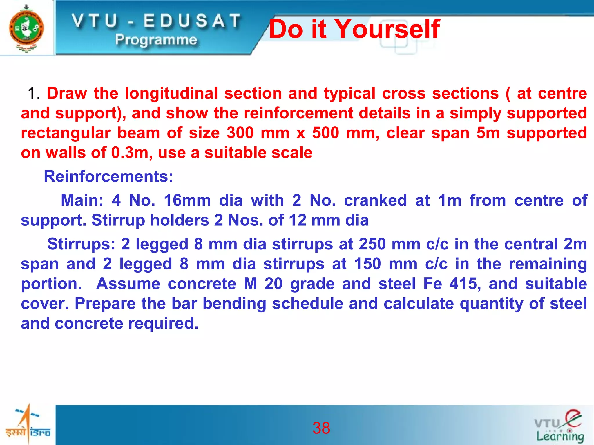
1
Design and drawing of RC
Structures
Email: gss_nie@yahoo.com
2
DETAILING OF
BEAM &SLAB
3
Learning out Come
• Review of detailing of beams
• Continuous rectangular beams
• Cantilever rectangular beams
• Flanged beams
• Introduction to detailing of slab
• One way slab
4
5
PROBLEM No. 3
Draw the Longitudinal section and two cross sections one near the
support and other near the mid span of a RCC continuous beam with
the following data:
Clear span of beams = 3m each
Width of beam = 200mm
Overall depth of beam = 300mm
Width in intermediate supports = 200 mm
Main reinforcement = 4 Nos -12 mm diameter bars with 2 bars bent up
Anchor/hanger bars= 2-10 mm diameter
Stirrups = 6 mm diameter @ 300 mm c/c.
Materials : HYSD bars and M20 grade concrete
6
PROBLEM No. 3
7
PROBLEM No. 4
A rectangular beam of cross section 300 x 450 mm is
supported on 4 columns which are equally spaced at 3m
c/c. The columns are of 300 mm x 300 mm in section. The
reinforcement consists of 4 bars of a6 mm diameter (+ve
reinforcement) at mid span and 4 bars of 16 mm diameter at
all supports (-ve reinforcement). Anchor bars consists of a
2-16 mm diameter. Stirrups are of 8 mm diameter 2 legged
vertical at 200 c/c throughout. Grade of concrete is M20 and
type of steel is Fe 415.
Draw longitudinal section and important cross sections.
8
PROBLEM No. 4
9
10
PROBLEM No. 5
Draw to scale of 1:20 the Longitudinal section and two cross-
section of a cantilever beam projecting 3.2 from a support using
following data
Clear span =3.2m
Overall depth at free end = 150 mm
Overall depth at fixed end = 450 mm
Width of cantilever beam = 300 mm
Main steel = 4-28 mm dia with two bars
curtailed at 1.5m from support
Anchor bars = 2 Nos. 16 mm dia
Nominal stirrups = 6mm dia at 40 mm c/c
Bearing at fixed end = 300 mm
Use M20 concrete and Fe 415 steel
11
PROBLEM No. 5
12
PROBLEM No. 6
A cantilever beam with 3.2m length is resting over a masonry wall and
supporting a slab over it. Draw to a suitable scale Longitudinal section,
two cross-sections and sectional plan with the following data:
Size of beam = 300 mm x 350 mm at free end and 300 mm x 450 mm at
fixed end and in the wall up to a length of 4.8m
Main steel: 4 nos. of 25 mm dia bars, two bars curtailed at 1.2m from
free end
Hanger bars: 2 nos. 16mm.
Stirrups: 6mm dia 2 legged stirrups @ 200 mm c/c the support length
and @100 mm c/c from fixed end up to length of 1m @ 150mm c/c up to
curtailed bars and remaining @ 200 c/c.
Use M20 concrete and Fe 415 steel
13
PROBLEM No. 2
14
15
PROBLEM No. 7
A beam has following data
Clear span = 4m
Support width = 300mm
Size of web = 350 x 400
Size of flange = 1200 x 120mm
Main reinforcement in two layers : 3-20 tor + 3-16 tor and to be
curtailed at a distance 400 mm from inner face of support
Hanger bars: 3- 20 tor
Stirrups: 2L-8 tor @ 200 c/c
Use M20 concrete and Fe 415 steel
Draw longitudinal and cross section if the beam is
1. T-beam
2. Inverted T-beam
3. L-Beam
16
PROBLEM No. 5
17
Dr.G.S.Suresh18
Introduction
• Used for covering spaces in the
form of roof or floor
• Slab may be supported on walls or
beams or columns .
• Slab supported directly by columns are
called flat slab
• One Way Slab
• Two Way Slab
Dr.G.S.Suresh19
Introduction
• Slabs could be simply supported,
continuous or cantilever
• In two way slab the corners may be held
down by restraints or may be allowed to
lift up
• Additional torsion reinforcement is
required at corners when it is restrained
against uplifting as shown in Fig
Dr.G.S.Suresh20
Introduction
Dr.G.S.Suresh21
Introduction
• Thickness of the slab is decided based on
span to depth ratio specified in IS456-2000.
Min reinforcement is 0.12% for HYSD bars and
0.15 % for mild steel bars.
• The maximum diameter of bar used in slab
should not exceed 1/8 of the total thickness of
slab
• Maximum spacing of main bar is restricted to
3 times effective depth or 300 mm which ever
is less
• For distribution bars the maximum spacing is
specified as 5 times the effective depth or 450
mm which ever is less
Dr.G.S.Suresh22
Introduction
• Generally 15 mm to 20 mm cover is
provided for the main reinforcements
• Alternate main bars can be cranked near
support or could be bent at 1800 at the
edge and then extended at the top inside
the slab as shown in Fig
• Curtailment and cranking of bars and is
shown in Fig
Dr.G.S.Suresh23
Introduction
Dr.G.S.Suresh24
Introduction
• Torsion Reinforcement shall be
provided as shown in Fig.
Dr.G.S.Suresh25
Torsion Reinforcement
Dr.G.S.Suresh26
Torsion Reinforcement
Dr.G.S.Suresh27
Typical One Way slab
Dr.G.S.Suresh28
Typical Two Way slab
29
PROBLEM
Prepare a detailed structural drawing of one way continuous slab for a
hall of clear dimensions 7m wide and 11.77 m long, use following data
Centre to centre distance of supporting beams = 3.0 m
Span of the beams = 7.23m
Beams are supported on walls of 0.23 m thickness
C/s of beam = 230 x 450 mm
Grade of concrete : M20
Type of steel : Fe415
Clear cover : 20 mm
Slab thickness: 150 mm
Beam depth is inclusive of slab depth, The hall is having walls on
all 4 sides
30
PROBLEM
Main positive reinforcement @ end span = 8mm
diameter @100 c/c
Main reinforcement in other interior panels = 8 mm
diameter @ 200 c/c
Negative reinforcement @ all supports = 8mm diameter
@ 200 c/c
Distribution steel= 8mm diameter @ 200 c/c
31
PROBLEM
32
33
No. 1
34
No. 2
35
No. 3
36
No. 4
37
No. 5
38
Do it Yourself
1. Draw the longitudinal section and typical cross sections ( at centre
and support), and show the reinforcement details in a simply supported
rectangular beam of size 300 mm x 500 mm, clear span 5m supported
on walls of 0.3m, use a suitable scale
Reinforcements:
Main: 4 No. 16mm dia with 2 No. cranked at 1m from centre of
support. Stirrup holders 2 Nos. of 12 mm dia
Stirrups: 2 legged 8 mm dia stirrups at 250 mm c/c in the central 2m
span and 2 legged 8 mm dia stirrups at 150 mm c/c in the remaining
portion. Assume concrete M 20 grade and steel Fe 415, and suitable
cover. Prepare the bar bending schedule and calculate quantity of steel
and concrete required.
39
Do it Yourself
2. Prepare the bar bending schedule and estimate quantity of steel and
concrete after drawing the longitudinal and cross section. Other details
are
Span of beam = 4.2 m
Cross section at support end 300 x 600 mm and cross section at
free end 300 x 150 mm
Reinforcements:
Main tension steel: 4-20 mm dia, 2 bars are curtailed at a distance
of 2m from free end
Hanger bars: 1-12 mm dia
Two legged stirrups 8mm dia @ 140 mm c/c for full length.
40
Dr. G.S.Suresh
Civil Engineering Department
The National Institute of Engineering
Mysore-570 008
Mob: 9342188467 Email: gss_nie@yahoo.com

Slabs Beam Reinforcement Detailing

  • 1.
    1 Design and drawingof RC Structures Email: gss_nie@yahoo.com
  • 2.
  • 3.
    3 Learning out Come •Review of detailing of beams • Continuous rectangular beams • Cantilever rectangular beams • Flanged beams • Introduction to detailing of slab • One way slab
  • 4.
  • 5.
    5 PROBLEM No. 3 Drawthe Longitudinal section and two cross sections one near the support and other near the mid span of a RCC continuous beam with the following data: Clear span of beams = 3m each Width of beam = 200mm Overall depth of beam = 300mm Width in intermediate supports = 200 mm Main reinforcement = 4 Nos -12 mm diameter bars with 2 bars bent up Anchor/hanger bars= 2-10 mm diameter Stirrups = 6 mm diameter @ 300 mm c/c. Materials : HYSD bars and M20 grade concrete
  • 6.
  • 7.
    7 PROBLEM No. 4 Arectangular beam of cross section 300 x 450 mm is supported on 4 columns which are equally spaced at 3m c/c. The columns are of 300 mm x 300 mm in section. The reinforcement consists of 4 bars of a6 mm diameter (+ve reinforcement) at mid span and 4 bars of 16 mm diameter at all supports (-ve reinforcement). Anchor bars consists of a 2-16 mm diameter. Stirrups are of 8 mm diameter 2 legged vertical at 200 c/c throughout. Grade of concrete is M20 and type of steel is Fe 415. Draw longitudinal section and important cross sections.
  • 8.
  • 9.
  • 10.
    10 PROBLEM No. 5 Drawto scale of 1:20 the Longitudinal section and two cross- section of a cantilever beam projecting 3.2 from a support using following data Clear span =3.2m Overall depth at free end = 150 mm Overall depth at fixed end = 450 mm Width of cantilever beam = 300 mm Main steel = 4-28 mm dia with two bars curtailed at 1.5m from support Anchor bars = 2 Nos. 16 mm dia Nominal stirrups = 6mm dia at 40 mm c/c Bearing at fixed end = 300 mm Use M20 concrete and Fe 415 steel
  • 11.
  • 12.
    12 PROBLEM No. 6 Acantilever beam with 3.2m length is resting over a masonry wall and supporting a slab over it. Draw to a suitable scale Longitudinal section, two cross-sections and sectional plan with the following data: Size of beam = 300 mm x 350 mm at free end and 300 mm x 450 mm at fixed end and in the wall up to a length of 4.8m Main steel: 4 nos. of 25 mm dia bars, two bars curtailed at 1.2m from free end Hanger bars: 2 nos. 16mm. Stirrups: 6mm dia 2 legged stirrups @ 200 mm c/c the support length and @100 mm c/c from fixed end up to length of 1m @ 150mm c/c up to curtailed bars and remaining @ 200 c/c. Use M20 concrete and Fe 415 steel
  • 13.
  • 14.
  • 15.
    15 PROBLEM No. 7 Abeam has following data Clear span = 4m Support width = 300mm Size of web = 350 x 400 Size of flange = 1200 x 120mm Main reinforcement in two layers : 3-20 tor + 3-16 tor and to be curtailed at a distance 400 mm from inner face of support Hanger bars: 3- 20 tor Stirrups: 2L-8 tor @ 200 c/c Use M20 concrete and Fe 415 steel Draw longitudinal and cross section if the beam is 1. T-beam 2. Inverted T-beam 3. L-Beam
  • 16.
  • 17.
  • 18.
    Dr.G.S.Suresh18 Introduction • Used forcovering spaces in the form of roof or floor • Slab may be supported on walls or beams or columns . • Slab supported directly by columns are called flat slab • One Way Slab • Two Way Slab
  • 19.
    Dr.G.S.Suresh19 Introduction • Slabs couldbe simply supported, continuous or cantilever • In two way slab the corners may be held down by restraints or may be allowed to lift up • Additional torsion reinforcement is required at corners when it is restrained against uplifting as shown in Fig
  • 20.
  • 21.
    Dr.G.S.Suresh21 Introduction • Thickness ofthe slab is decided based on span to depth ratio specified in IS456-2000. Min reinforcement is 0.12% for HYSD bars and 0.15 % for mild steel bars. • The maximum diameter of bar used in slab should not exceed 1/8 of the total thickness of slab • Maximum spacing of main bar is restricted to 3 times effective depth or 300 mm which ever is less • For distribution bars the maximum spacing is specified as 5 times the effective depth or 450 mm which ever is less
  • 22.
    Dr.G.S.Suresh22 Introduction • Generally 15mm to 20 mm cover is provided for the main reinforcements • Alternate main bars can be cranked near support or could be bent at 1800 at the edge and then extended at the top inside the slab as shown in Fig • Curtailment and cranking of bars and is shown in Fig
  • 23.
  • 24.
  • 25.
  • 26.
  • 27.
  • 28.
  • 29.
    29 PROBLEM Prepare a detailedstructural drawing of one way continuous slab for a hall of clear dimensions 7m wide and 11.77 m long, use following data Centre to centre distance of supporting beams = 3.0 m Span of the beams = 7.23m Beams are supported on walls of 0.23 m thickness C/s of beam = 230 x 450 mm Grade of concrete : M20 Type of steel : Fe415 Clear cover : 20 mm Slab thickness: 150 mm Beam depth is inclusive of slab depth, The hall is having walls on all 4 sides
  • 30.
    30 PROBLEM Main positive reinforcement@ end span = 8mm diameter @100 c/c Main reinforcement in other interior panels = 8 mm diameter @ 200 c/c Negative reinforcement @ all supports = 8mm diameter @ 200 c/c Distribution steel= 8mm diameter @ 200 c/c
  • 31.
  • 32.
  • 33.
  • 34.
  • 35.
  • 36.
  • 37.
  • 38.
    38 Do it Yourself 1.Draw the longitudinal section and typical cross sections ( at centre and support), and show the reinforcement details in a simply supported rectangular beam of size 300 mm x 500 mm, clear span 5m supported on walls of 0.3m, use a suitable scale Reinforcements: Main: 4 No. 16mm dia with 2 No. cranked at 1m from centre of support. Stirrup holders 2 Nos. of 12 mm dia Stirrups: 2 legged 8 mm dia stirrups at 250 mm c/c in the central 2m span and 2 legged 8 mm dia stirrups at 150 mm c/c in the remaining portion. Assume concrete M 20 grade and steel Fe 415, and suitable cover. Prepare the bar bending schedule and calculate quantity of steel and concrete required.
  • 39.
    39 Do it Yourself 2.Prepare the bar bending schedule and estimate quantity of steel and concrete after drawing the longitudinal and cross section. Other details are Span of beam = 4.2 m Cross section at support end 300 x 600 mm and cross section at free end 300 x 150 mm Reinforcements: Main tension steel: 4-20 mm dia, 2 bars are curtailed at a distance of 2m from free end Hanger bars: 1-12 mm dia Two legged stirrups 8mm dia @ 140 mm c/c for full length.
  • 40.
    40 Dr. G.S.Suresh Civil EngineeringDepartment The National Institute of Engineering Mysore-570 008 Mob: 9342188467 Email: gss_nie@yahoo.com