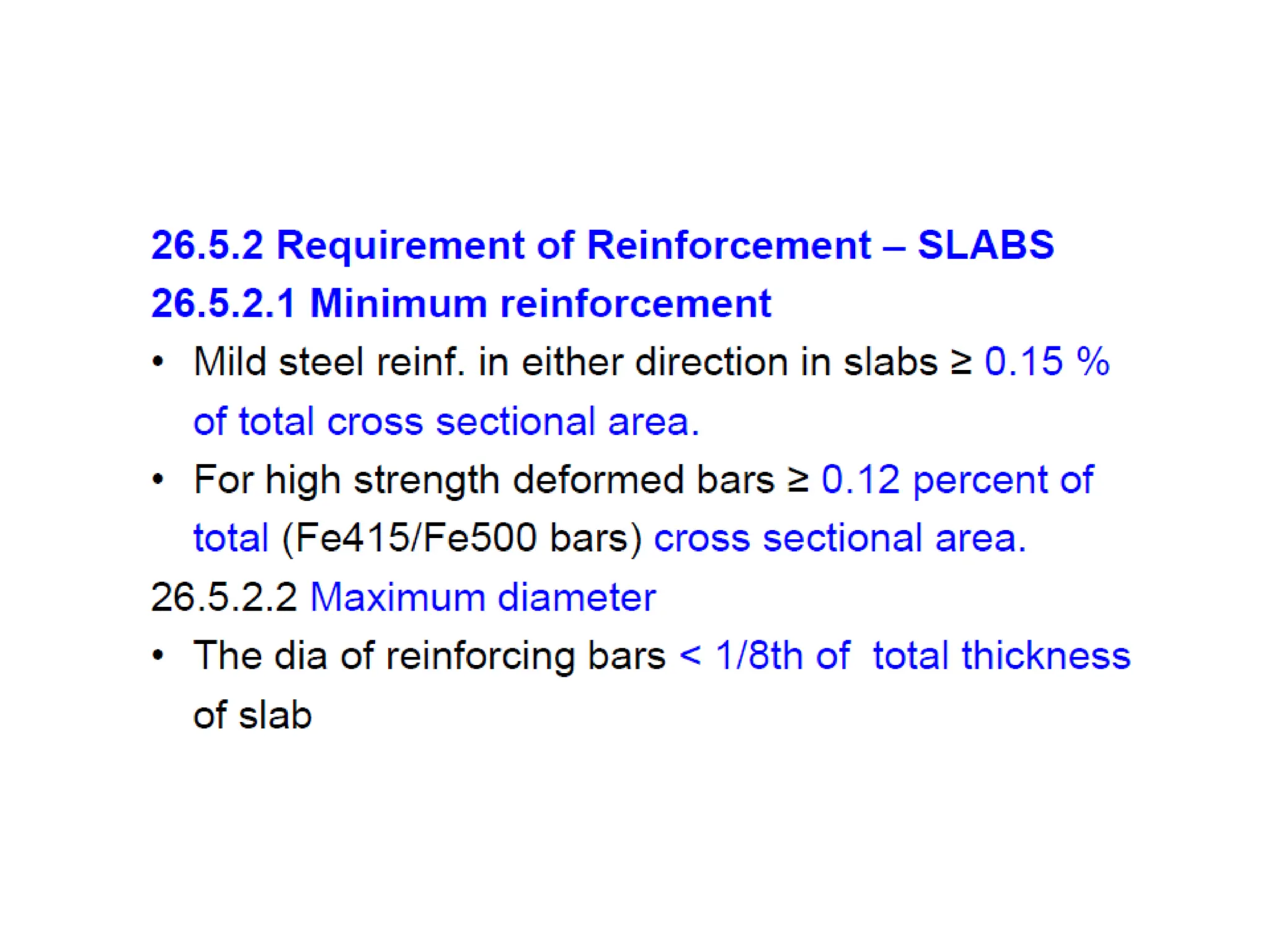
The document provides a comprehensive overview of reinforced cement concrete (RCC) construction, outlining its components, advantages, and disadvantages. It discusses various concrete mix ratios for different applications, stages of structural design, and necessary specifications for steel and beam construction. Additionally, it details the design principles for slabs and beams, emphasizing effective spans, loading requirements, and appropriate reinforcements.


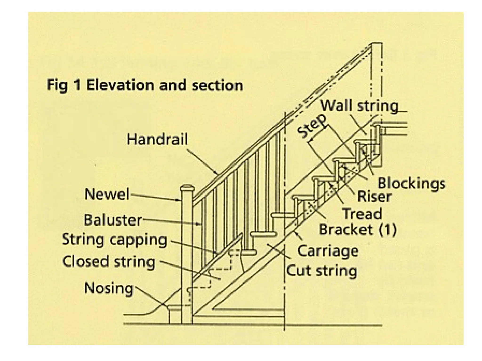
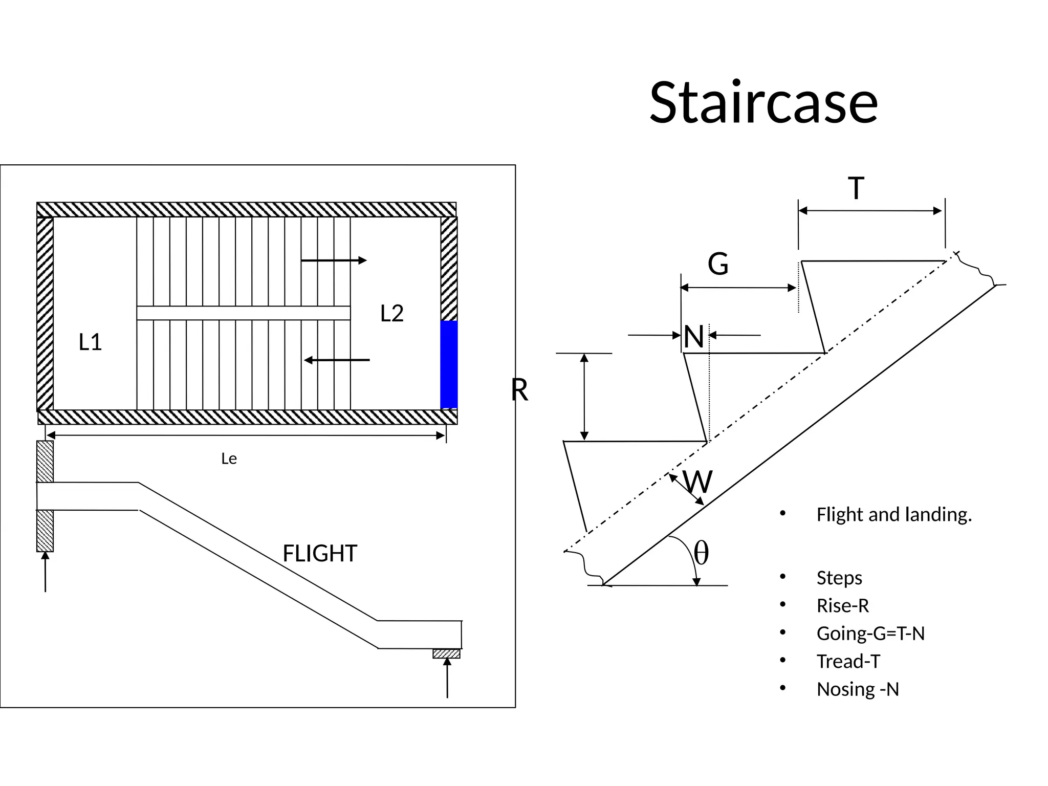
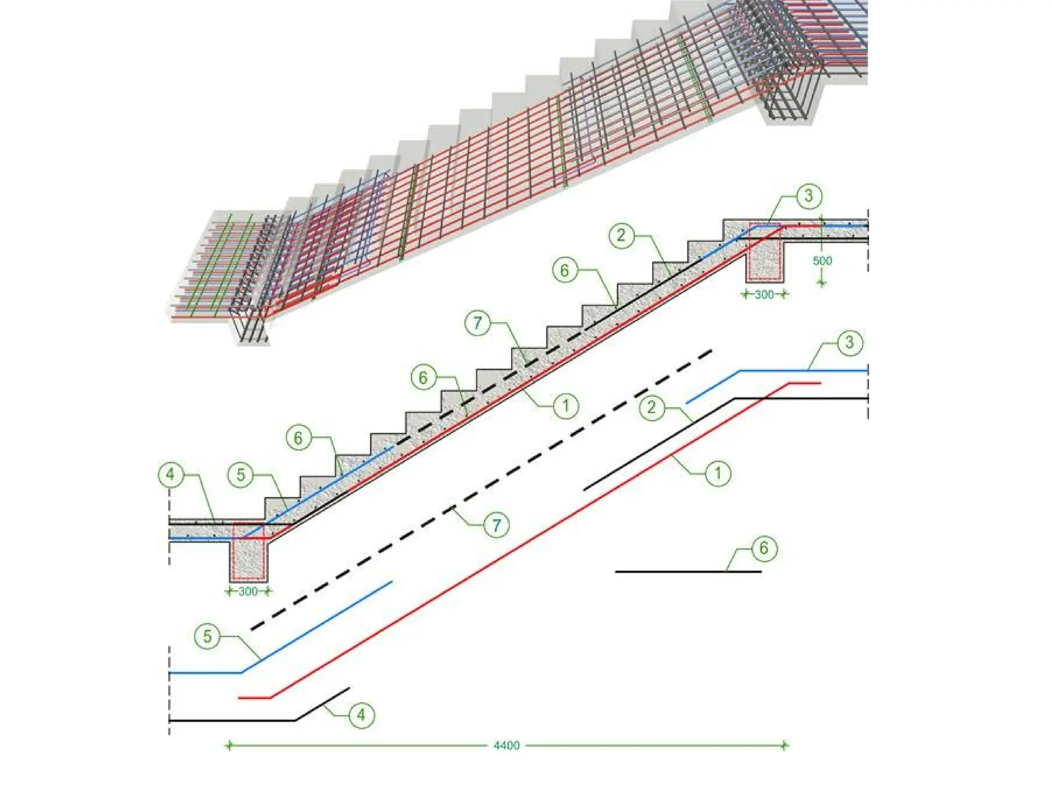
![• Rise (R) : 150mm to 180mm
• Tread (T) : 220 mm to300 mm- for residential buildings.
• Rise (R) : 120 to 150 mm
• Tread (T) : 250 mm to 300 mm – for public buildings
[T + 2R] : Between 500 mm to 650 mm
The width of the stair
• 0.8 m to 1 m for residential building and
• 1.8 m to 2 m for public building.](https://image.slidesharecdn.com/btechsem3notes-240917161504-f10672d6/75/BTech-Sem-3-notes-pptxARARQQDWQEE2E2DSR4E-WR3RD3-V-118-2048.jpg)