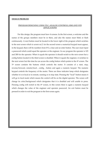
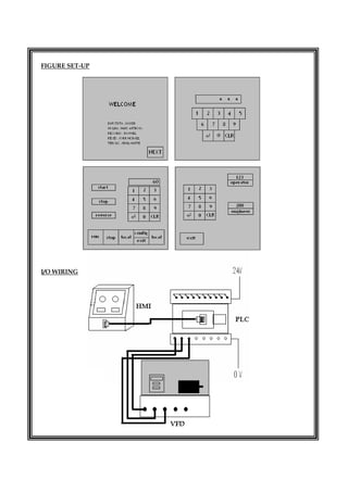
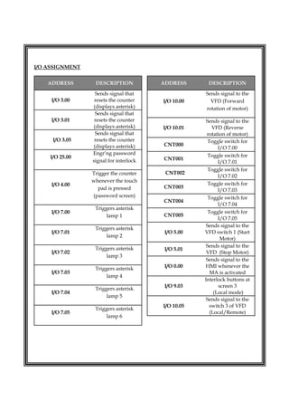
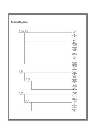
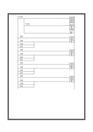
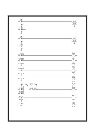
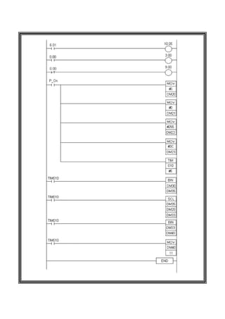
MAPUA INSTITUTE OF TECHNOLOGY
SCHOOL OF EE-ECE-CoE
DESIGN TASK
PROGRAM DESIGNING USING PLC, ANALOG
CONTROLS, HMI AND VFD APPLICATION
DATE PERFORMED: NOVEMBER 16, 2007
DATE SUBMITTED: NOVEMBER 27, 2007
COURSE / SECTION: ACON413P / B7
GROUP NO.: 4
MEMBERS:
BAUTISTA, JASPER
MOLINA, MARK ANTHONY
RECONDO JR., ROMMEL
REYES, JOHN MICHAEL
TERCIAS, JEMIL MARTE
ENGR. JOSEPH BRYAN IBARRA
INSTRUCTOR
 
DESIGN PROBLEM
PROGRAM DESIGNING USING PLC, ANALOG CONTROLS, HMI AND VFD
APPLICATIONS
For this design, the program must have 4 screens. In the first screen, a welcome and the
names of the groups members must be in there, and also the names must blink or flash
continuously. A next button must be located in the lower right of the program which switches
to the next screen which is screen no.2. for the second screen a numerical keypad must appear,
in the keypad, there will be numbers from 0-9, a clear and an enter button. The user must input
a password which could equal the operator or the engineer. In our program the operator is 123
and 200 for the operator. When it equals the operator it should switch to the next screen but a
config button located in the third screen is disabled. When it equals the engineer, it switches to
the next screen but this time he can access the config button which points to the 4th screen. The
3rd screen contains the buttons which controls the motor. It consists of a start, stop,
reverse/forward, remote/local , config , button and again a numeric keypad. The numeric
keypad controls the frequency of the motor. There are three indicator lamp which designates
whether it is in local or in remote, running or in stop state. Pressing the “local” button means it
will go to local mode which means the control will be on the digital operator. The screen will
change its color/background which designates that it is disabled and will unable to press.
Pressing config will switch to the 4th screen, in this screen there is again a numeric keypad
which changes the value of the engineer and operator password. An exit button must be
pressed in order to exit the program to the first screen again.
 
FIGURE SET-UP
I/O WIRING
 
I/O ASSIGNMENT
ADDRESS DESCRIPTION
I/O 3.00
Sends signal that
resets the counter
(displays asterisk)
I/O 3.01
Sends signal that
resets the counter
(displays asterisk)
I/O 3.05
Sends signal that
resets the counter
(displays asterisk)
I/O 25.00
Engr’ng password
signal for interlock
I/O 4.00
Trigger the counter
whenever the touch
pad is pressed
(password screen)
I/O 7.00
Triggers asterisk
lamp 1
I/O 7.01
Triggers asterisk
lamp 2
I/O 7.02
Triggers asterisk
lamp 3
I/O 7.03
Triggers asterisk
lamp 4
I/O 7.04
Triggers asterisk
lamp 5
I/O 7.05
Triggers asterisk
lamp 6
ADDRESS DESCRIPTION
I/O 10.00
Sends signal to the
VFD (Forward
rotation of motor)
I/O 10.01
Sends signal to the
VFD (Reverse
rotation of motor)
CNT000
Toggle switch for
I/O 7.00
CNT001
Toggle switch for
I/O 7.01
CNT002
Toggle switch for
I/O 7.02
CNT003
Toggle switch for
I/O 7.03
CNT004
Toggle switch for
I/O 7.04
CNT005
Toggle switch for
I/O 7.05
I/O 5.00
Sends signal to the
VFD switch 1 (Start
Motor)
I/O 5.01
Sends signal to the
VFD (Stop Motor)
I/O 0.00
Sends signal to the
HMI whenever the
MA is activated
I/O 9.03
Interlock buttons at
screen 3
(Local mode)
I/O 10.05
Sends signal to the
switch 3 of VFD
(Local/Remote)
 
LADDER DIAGRAM


DESIGN ACON

  • 1.
      MAPUA INSTITUTE OFTECHNOLOGY SCHOOL OF EE-ECE-CoE DESIGN TASK PROGRAM DESIGNING USING PLC, ANALOG CONTROLS, HMI AND VFD APPLICATION DATE PERFORMED: NOVEMBER 16, 2007 DATE SUBMITTED: NOVEMBER 27, 2007 COURSE / SECTION: ACON413P / B7 GROUP NO.: 4 MEMBERS: BAUTISTA, JASPER MOLINA, MARK ANTHONY RECONDO JR., ROMMEL REYES, JOHN MICHAEL TERCIAS, JEMIL MARTE ENGR. JOSEPH BRYAN IBARRA INSTRUCTOR
  • 2.
      DESIGN PROBLEM PROGRAM DESIGNINGUSING PLC, ANALOG CONTROLS, HMI AND VFD APPLICATIONS For this design, the program must have 4 screens. In the first screen, a welcome and the names of the groups members must be in there, and also the names must blink or flash continuously. A next button must be located in the lower right of the program which switches to the next screen which is screen no.2. for the second screen a numerical keypad must appear, in the keypad, there will be numbers from 0-9, a clear and an enter button. The user must input a password which could equal the operator or the engineer. In our program the operator is 123 and 200 for the operator. When it equals the operator it should switch to the next screen but a config button located in the third screen is disabled. When it equals the engineer, it switches to the next screen but this time he can access the config button which points to the 4th screen. The 3rd screen contains the buttons which controls the motor. It consists of a start, stop, reverse/forward, remote/local , config , button and again a numeric keypad. The numeric keypad controls the frequency of the motor. There are three indicator lamp which designates whether it is in local or in remote, running or in stop state. Pressing the “local” button means it will go to local mode which means the control will be on the digital operator. The screen will change its color/background which designates that it is disabled and will unable to press. Pressing config will switch to the 4th screen, in this screen there is again a numeric keypad which changes the value of the engineer and operator password. An exit button must be pressed in order to exit the program to the first screen again.
  • 3.
  • 4.
      I/O ASSIGNMENT ADDRESS DESCRIPTION I/O3.00 Sends signal that resets the counter (displays asterisk) I/O 3.01 Sends signal that resets the counter (displays asterisk) I/O 3.05 Sends signal that resets the counter (displays asterisk) I/O 25.00 Engr’ng password signal for interlock I/O 4.00 Trigger the counter whenever the touch pad is pressed (password screen) I/O 7.00 Triggers asterisk lamp 1 I/O 7.01 Triggers asterisk lamp 2 I/O 7.02 Triggers asterisk lamp 3 I/O 7.03 Triggers asterisk lamp 4 I/O 7.04 Triggers asterisk lamp 5 I/O 7.05 Triggers asterisk lamp 6 ADDRESS DESCRIPTION I/O 10.00 Sends signal to the VFD (Forward rotation of motor) I/O 10.01 Sends signal to the VFD (Reverse rotation of motor) CNT000 Toggle switch for I/O 7.00 CNT001 Toggle switch for I/O 7.01 CNT002 Toggle switch for I/O 7.02 CNT003 Toggle switch for I/O 7.03 CNT004 Toggle switch for I/O 7.04 CNT005 Toggle switch for I/O 7.05 I/O 5.00 Sends signal to the VFD switch 1 (Start Motor) I/O 5.01 Sends signal to the VFD (Stop Motor) I/O 0.00 Sends signal to the HMI whenever the MA is activated I/O 9.03 Interlock buttons at screen 3 (Local mode) I/O 10.05 Sends signal to the switch 3 of VFD (Local/Remote)
  • 5.
  • 6.
  • 7.
  • 8.