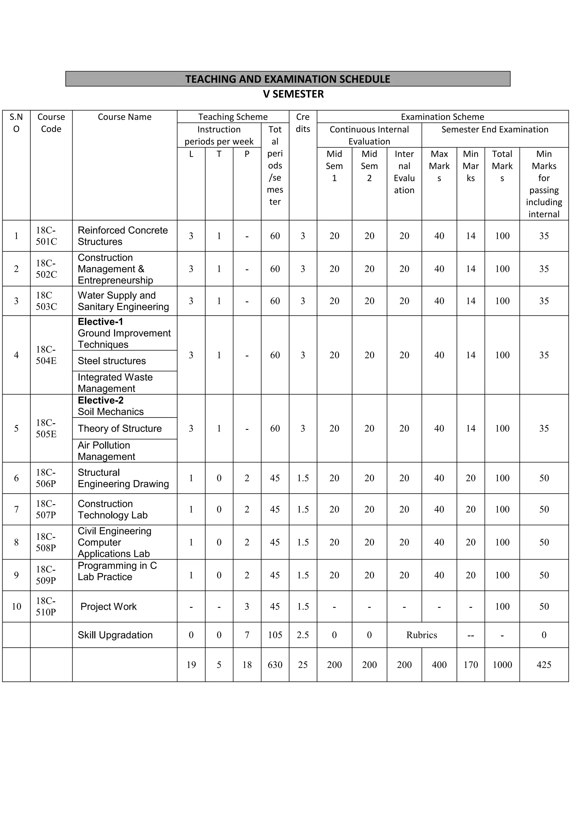
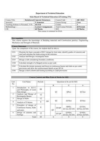
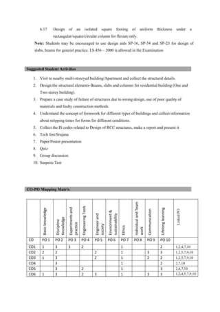
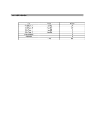
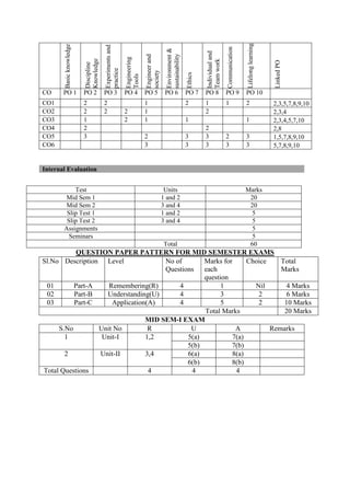
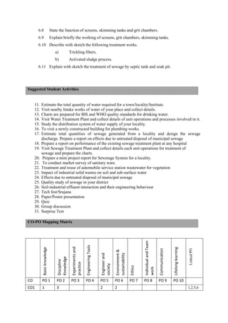
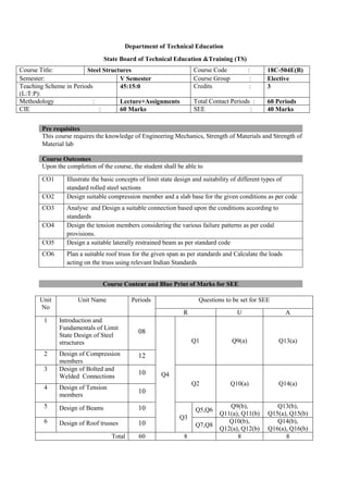
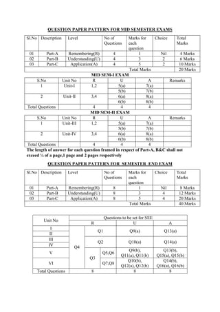
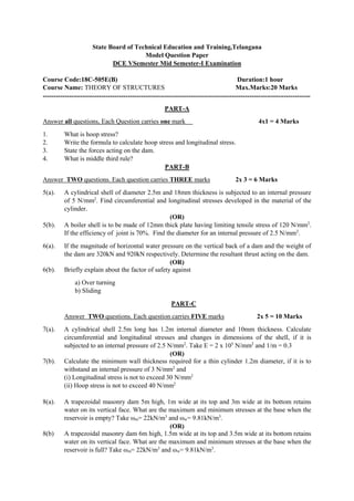
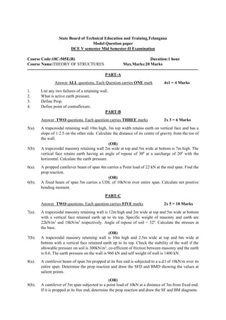
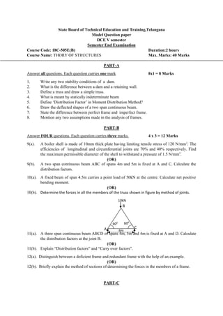
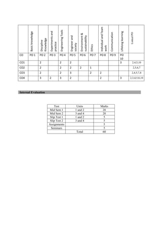
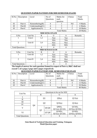
The document provides the teaching and examination schedule for the 5th semester of a civil engineering course. It includes the list of courses being taught, the teaching scheme detailing the instruction periods and credits for each course, and the examination scheme specifying the evaluation parameters for continuous internal evaluation and semester end examination. The courses include Reinforced Concrete Structures, Construction Management and Entrepreneurship, Water Supply and Sanitary Engineering, electives, structural engineering drawing, construction technology lab, civil engineering computer applications lab, programming in C lab, and project work. The document also provides the course content and blue print of marks for the semester end examination of Reinforced Concrete Structures course.


![State Board of Technical Education and Training, Telangana
Model Question paper
DCE V Semester
Mid Semester-II Examination
Course Code: 18C-506P Duration: 1 Hour
Course Name: Structural Engineering Drawing Max.Marks: 20 Marks
PART-A
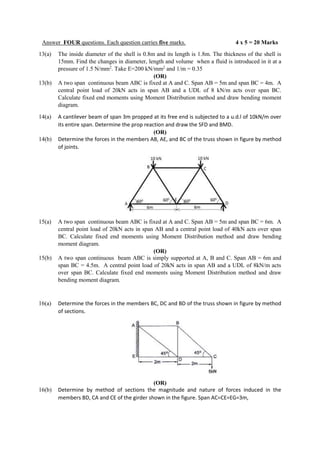
Answer all questions. Each question carries four marks
2x4=8Marks
Instructions : (1) To be drawn not to scale.
(2) Assume suitable data, if necessary.
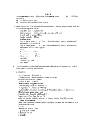
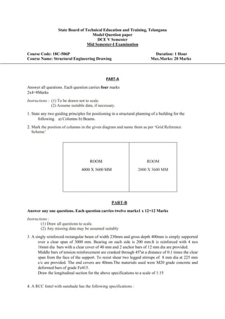
1. Draw the cross section showing reinforcement details of simply supported one way slab along
shorter span with the following specifications
I. Clear span [shorter] = 2.8m
II. Clear span [longer ] = 6.0m
III. Bearing on all the sides = 230mm
IV. Overall depth of the slab = 130mm
V. Steel
Main steel = # 10 at 170mm c/c, all main bars are cranked on one side alternatively at
a distance of 280mm from the face of the support.
Distribution steel = # 8 @ 200mmc/c
Hanger bars = 3 # 8 on each side (to support cranked bars)
VI. Covers
Bottom clear cover=20mm
Top clear cover = 20mm
Side covers = 25mm
VII. Materials
Concrete = M 20 grade concrete
Steel = Fe415
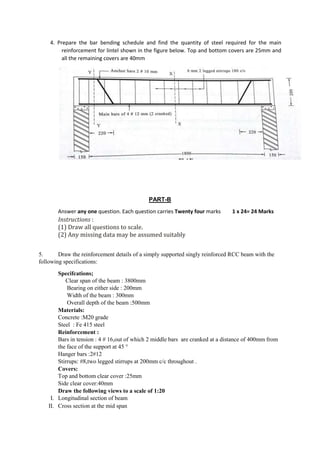
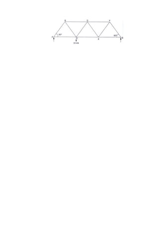
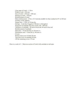
2. Prepare the bar bending schedule and find the total quantity of steel required for one way
slab shown in figure below. Top and bottom covers are 20 mm and side cover is 25mm.](https://image.slidesharecdn.com/dce-230311112156-82e9633f/85/DCE-DOCX-122-320.jpg)