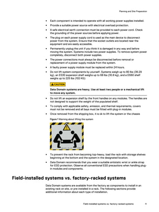
This document provides guidance on planning the installation of a Dell EMC Data Domain DD6300 system. It discusses tools needed, safety information, and the differences between field-installed systems versus factory-racked systems. The tools and supplies section lists various hardware items that may be useful for installation. Safety precautions are also outlined, including warnings about the heavy weight of systems and following electrostatic discharge procedures. Field-installed systems are shipped as individual components to be installed in an existing rack, while factory-racked systems are pre-installed in a rack.


![Note
If you type an incorrect password four consecutive times, the system locks out the
specified username for 120 seconds. The login count and lockout period are
configurable and might be different on your system. See the Data Domain Operating
System Administration Guide and the Data Domain Operating System Command
Reference Guide for setting these values.
Accepting the End User License Agreement
The first time you log in to a Data Domain system, the End User License Agreement
(EULA) is displayed.
At the end of the EULA, you are prompted to accept it:
Press any key then hit enter to acknowledge the receipt of EULA
information
Note
The customer must accept the EULA. A Data Domain representative should not accept
this agreement. If a customer is not present, press Ctrl-C to exit from the EULA
acceptance screen and continue the installation.
The customer can later type the following to redisplay the EULA and accept it:
system show eula
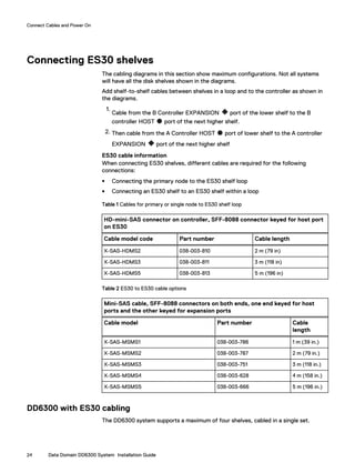
Run the configuration wizard
The CLI configuration wizard starts automatically the first time the system starts. The
wizard prompts you through a series of questions that provide just enough information
for initial system configuration and basic network connectivity.
Note
You can begin the CLI configuration wizard manually by typing config setup.
Configuring the network
Procedure
1. Enter yes to configure the system for network connectivity.
Network Configuration
Configure Network at this time (yes|no) [no]:
yes
2. Enter yes to configure DHCP (Dynamic Host Configuration Protocol) to obtain
network parameters (such as, the host name, domain name, and IP addresses)
dynamically from a DHCP server. Or enter no to configure the parameters
manually.
Use DHCP
Use DHCP for hostname, domainname, default gateway
and DNS servers? (At least one interface needs to
be configured using DHCP) (yes|no|?)
3. Enter a fully qualified domain name (FQDN) for the host name; for example,
str01.yourcompany.com. Or accept the host name, if the system was able to
discover it.
Configure System for Use
Accepting the End User License Agreement 33](https://image.slidesharecdn.com/datadomain-181105053035/85/Data-EMC-Data-domain-DD6300-System-33-320.jpg)
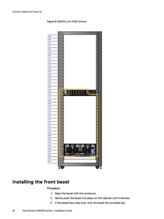
![Enter the hostname for this system
(fully-qualified domain name)[]:
4. Enter the DNS (Domain Name System) domain name; for example,
yourcompany.com. Or accept the domain name, if the system was able to
discover it.
Domainname
Enter your DNS domainname []:
5. Enable and configure each Ethernet interface. Accept or decline DHCP for each
interface. If the port does not use DHCP to discover network parameters
automatically, enter the information manually.
Ethernet port eth0a
Enable Ethernet port eth0a (yes|no|?) [yes]:
no
Ethernet port eth0b
Enable Ethernet port eth0b (yes|no|?) [no]:
yes
Use DHCP on Ethernet port eth0b (yes|no|?) [no]:
Enter the IP address for eth0b [192.168.10.185]:
Enter the netmask for eth0b [255.255.255.0]:
6. Enter the IP address of the default routing gateway. Or accept the default
gateway, if the system was able to discover it.
Default Gateway
Enter the default gateway IP address:
192.168.10.1
7. Enter the IPv6 address of the default routing gateway. Or accept the IPv6
address of the default gateway, if the system was able to discover it. If IPv6 is
not in use, leave the field empty, and press Enter to continue.
IPV6 Default Gateway
Enter the ipv6 default gateway IP address:
8. Enter up to three DNS servers to use for resolving host names to IP addresses.
Use a comma-separated or space-separated list. Enter a space for no DNS
servers. Or accept the IP addresses of the DNS servers, if the system was able
to discover them.
DNS Servers
Enter the DNS Server list (zero, one, two or three IP
addresses):
192.168.10.1
9. A summary of the network settings is displayed. You can accept the settings
(Save), reject the settings and exit to the CLI (Cancel), or return to the
beginning of the current section and change the settings (Retry). Entering
Retry displays your previous responses for each prompt. Press Return to
accept the displayed value or enter a new one.
Pending Network Settings
Hostname ddbeta1.dallasrdc.com
Domain name dallasrdc.com
Default Gateway 192.168.10.1
DNS Server List 192.168.10.1
Port Enabled Cable DHCP IP Address Netmask or Prefix Length
----- ------- ----- ---- -------------- ------------------------
eth0a no no n/a n/a n/a
eth0b no no n/a n/a n/a
eth0c no no n/a n/a n/a
eth0d no no n/a n/a n/a
ethMa yes yes no 192.168.10.181 255.255.255.0
ethMb no no n/a n/a n/a
Configure System for Use
34 Data Domain DD6300 System Installation Guide](https://image.slidesharecdn.com/datadomain-181105053035/85/Data-EMC-Data-domain-DD6300-System-34-320.jpg)
![ethMc no no n/a n/a n/a
ethMd no no n/a n/a n/a
ethMe no no n/a n/a n/a
ethMf no no n/a n/a n/a
----- ------- ----- ---- -------------- ------------------------
Do you want to save these settings (Save|Cancel|Retry):
Configuring additional system parameters
Most installations would benefit from the configuration of a few additional system
parameters, provided in this section for convenience.
Note
You can also use the Data Domain (DD) System Manager GUI interface to configure
the system parameters. Open a web browser, and enter your Data Domain system’s IP
address in the browser’s address text box. Log in when the DD System Manager login
screen displays. Use the DD System Manager online help for more information.
Procedure
1. To set up the mail server, enter:
# config set mailserver mail.datadomain.com
The Mail (SMTP) server is: mail.datadomain.com
2. To set up the system location, enter:
# config set location "Dallas Regional Data Center Lab,
5000 Apple Drive Suite #130, Dallas, Tx"
The System Location is: Dallas Regional Data Center Lab,
5000 Apple Drive Suite #130, Dallas, Tx
3. To add one or more time servers, enter:
# ntp add timeserver 192.168.101.1
Remote Time Servers: 192.168.10.1
4. To enable the NTP daemon, enter:
# ntp enable
NTP enabled.
5. To change the system time zone, enter:
# config set timezone US/Central
The Timezone name is: US/Central
*** You made a change to the timezone setting. To fully effect
this change
*** (in currently running processes), you need to reboot the
machine.
6. Reboot the system for the time zone change to take effect:
# system reboot
The 'system reboot' command reboots the system. File access is
interrupted during the reboot.
Are you sure? (yes|no|?) [no]: yes
ok, proceeding.
The system is going down for reboot.
7. After the system completes the reboot, login again as sysadmin using the serial
number as a password. Press Ctrl-C to get through the EULA, sysadmin
password prompt, and config setup wizard.
8. Generate an autosupport sent to yourself to use as ACG input:
# autosupport send your.email@emc.com
OK: Message sent.
Configure System for Use
Configuring additional system parameters 35](https://image.slidesharecdn.com/datadomain-181105053035/85/Data-EMC-Data-domain-DD6300-System-35-320.jpg)


