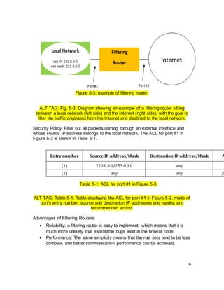
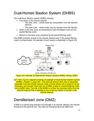
The document discusses firewall technologies and architectures. It begins by explaining the need for firewalls to protect internal networks from external threats. It then describes various firewall types including filtering routers, which inspect IP and TCP/UDP headers; stateful inspection, which tracks connection states; circuit gateways, which operate at the transport layer; and proxy servers, which break direct connections and mediate traffic. It provides examples of how each type of firewall works and their advantages and limitations. It also covers firewall configurations like the single-homed bastion system.
![10
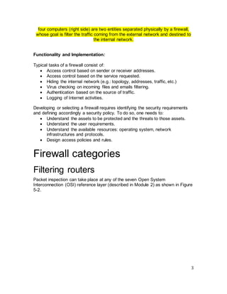
ALT TAG: Table 5-4. Table displaying the connection tracking states used in
building the rules.
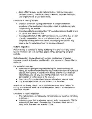
An example of connection state table is shown in Table 5-5.
Client
address
219.22.101.
32
219.22.101.
54
210.99.201.
14
24.102.129.
21
Client
port
1030 1034 2001 3389
Server
address
129.63.24.8
4
129.63.24.8
4
129.63.24.8
7
129.63.24.8
7
Server
port
25 161 80 110
Connectio
n state
established established established established
Protocol TCP UDP TCP TCP
Table 5-5: An example of connection state table.
[Isaac Woungang Copyright 2012]
ALT TAG: Table 5-5. A table showing the state of connection (in this case
“established”) between a series of five clients and a given server, both identified
by their addresses, port numbers that they used to connect to the server, and
protocols that is followed (TCP or UDP).
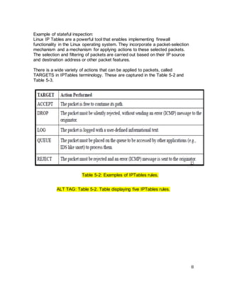
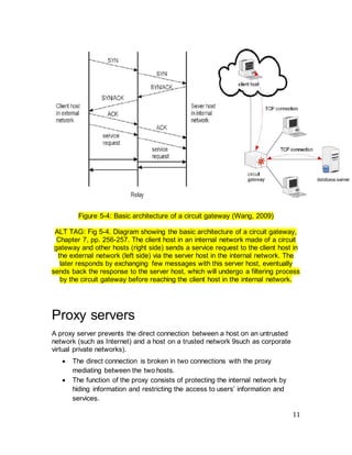
Circuit gateways
Circuit gateways operate at the transport layer. Their purpose is to examine
information of IP addresses and port numbers in TCP/UDP headers to determine
if a connection is allowed. Usually, they are combined with a packet filter to form
a dynamic packet filter.
Typically, a circuit gateway is meant to:
• Relay a TCP connection between an internal and external host.
• Disallow the direct connection between the external and the internal
networks.
• Maintain a table for valid connection and check incoming packet against
that table.
Its basic structure is depicted in Figure 5-4.](https://image.slidesharecdn.com/cryptographyprojectbyaelsayedkyasser-240313165631-d3f13d9e/85/Cryptography-Project-by-Aelsayed-Kyasser-pdf-10-320.jpg)
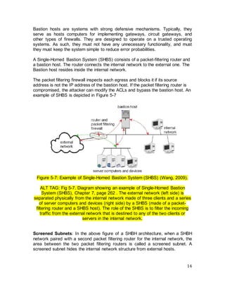
![19
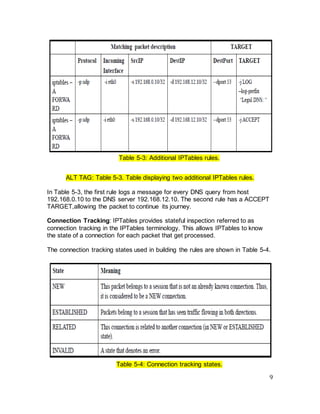
untrustworthy host. The host is referred to as untrustworthy because it cannot be
protected by the firewall. An example of such architecture is shown in the figure
below:
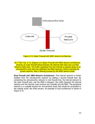
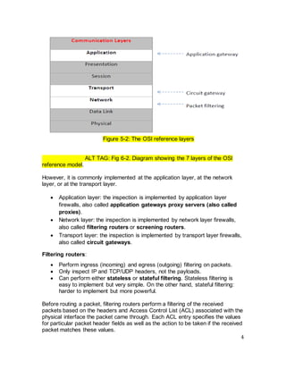
Figure 5-12: Basic Border Firewall with Untrustworthy architecture.
[Isaac Woungang Copyright 2012]
ALT TAG: Fig. 5-12. Diagram of a Basic Border Firewall with Untrustworthy
architecture, showing an outer firewall sitting between the Internet (left side) and
a private network (right side). The traffic originated from the Internet is passed
along to an untrustworthy host (left side), before reaching the outer firewall,
whose role is to filter that traffic before passing it to the private network.
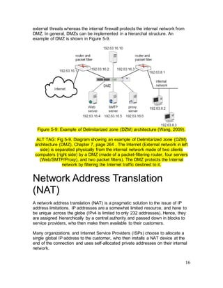
Basic Firewall with DMZ Network Architecture: In a DMZ network, the
untrusted host is brought “inside” the firewall, but placed on a network by itself
(the firewall host then interconnects three networks). This type of architecture
increases the security, reliability, and availability of the untrusted host, but it does
not increase the level of trust that other “inside” hosts can afford it. Other
untrustworthy hosts designed for other purpose (for example, a public web site or
ftp server) can easily be placed on the DMZ network, creating a public services
network. An example of such architecture is shown in Figure 5.13.](https://image.slidesharecdn.com/cryptographyprojectbyaelsayedkyasser-240313165631-d3f13d9e/85/Cryptography-Project-by-Aelsayed-Kyasser-pdf-19-320.jpg)