An Efficient VLSI Design for Extracting Local Binary Pattern
Cross_Integration_Poster
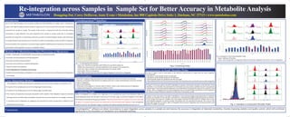
1. Re-integration across Samples in Sample Set for Better Accuracy in Metabolite Analysis
Hongping Dai, Corey DeHaven, Anne Evans • Metabolon, Inc 800 Capitola Drive Suite 1, Durham, NC 27713 • www.metabolon.com
Introduction
Due to their high throughput and sensitivity, GC/MS and UHPLC/MS/MS2 are widely used in metabolomic
studies. Such high throughput analyses produce a large amount of raw scan data that need to be automatically
processed from sample to sample. The quality of the results is compromised with the inherently existing
inconsistency in peak detection and peak integration from sample to sample, partly due to incomplete
separation of compounds or overloading commonly occurred in complex biological samples. New techniques
areneededtodetectandovercomesuchinconsistencyinordertoachievehighaccuracy.Ionpeakre-integration
across all samples in the sample set is a novel technique capable of detecting and correcting such inconsistency
and therefore achieving better accuracy in metabolite analysis.
Cross-Integration Strategy
Chromatograms of Peaks representing the quantitative mass from all the samples are evaluated to see
• If majority of the sample peaks are on the trailing edge of another peak,
• If majority of the sample peaks are on the leading edge of another peak,
• If the majority are peaks that encompass two peaks in other samples. Peak integration ranges are evaluated
with alignment by retention index and statistics of peak limits across the sample set. Accordingly, corrections
in consistency and re-integration are suggested and presented for review and approval, in addition to user
specified manual correction.
Workflow in Metabolomics Data Processing at Metabolon
• GC/MS, LC(NEG)/MSn
and LC(POS)/MSn
measurement of metabolite samples.
• Automatic Ion Peak Detection and Peak Integration
• Automatic Ion Peak Componentization
• Automatic Library Matches to Identify Metabolites
• Manual Curation of metabolites
• Cross-Integration for Consistency and Accuracy
• Statistics (Historical Statistics and Statistics in the sample set), Quality Control and Elucidation of Metabolism
and Pathway.
CrossIntegrationTM
Interface
Fig. 1. CrossIntegrationTM Interface:
Upper Left : Identified metabolites (200~600) in the specified sample set;
Middle Left: quant peaks for selected metabolite in the samples in the sample set;
Lower Left: Type of samples and Information about the sample peaks
Upper Right: Peak chromatograms
Lower Right: Sample peak area (blue for original integration and red for re-integrated
Combining Peaks
When a metabolite in a sample is at a high level, it can overload the column and therefore distort the
chromatographic peak. Even through it may be out of the linear range, a consistent integration of the peak is
still needed to characterize the group of samples. Distorted peaks produce wrong pick of the quant mass peak.
In Figure 2, the peak for glucose was inaccurately split by the automated peak integrator. Cross-reintegration
would correct this. The example in Figure 2 improves the relative standard deviation from 20.1 to 7.4.
Conclusion CrossIntegrationTM
software can detect inconsistency in peak integration across samples in a sample set and improve the accuracy in integration of detected metabolites, thereby improving statistics and quality control, which will contribute
significantly to the elucidation of metabolism and metabolite pathway.
Fig. 1. CrossIntegrationTM Interface:
Upper Left : Identified metabolites (200~600) in the specified sample set;
Middle Left: quant peaks for selected metabolite in the samples in the sample set;
Lower Left: Type of samples and Information about the sample peaks
Upper Right: Peak chromatograms
Lower Right: Sample peak area (blue for original integration and red for re-integrated
CrossIntegrationTM Interface
Functionalities
• Automatic merging of approved peaks from the sample that match to the same lib compound.
• Detection of Shoulder Peaks Based on RI-aligned peak start or peak end distribution across the samples.
• Manual Integration
• Manual Peak Splitting
• Show peak chromatograms in overlay mode or tabular mode to easy review/manual re-integration.
• Update peak integrations, peak recovery and lib re-match
Fig.2. Combining Peaks
Fig.2. Combining Peaks
0.0
2.0
4.0
6.0
0.0
2.0
4.0
6.0
0.0
2.0
4.0
6.0
0.0
2.0
4.0
6.0
0.0
2.0
4.0
6.0
0.0
2.0
4.0
6.0
0.0
2.0
4.0
6.0
0.0
2.0
4.0
6.0
0.0
2.0
4.0
6.0
0.0
2.0
4.0
6.0
Intensity/10,000,000
1850.0 1855.0 1860.0 1865.0 1870.0 1875.0 1850.0 1855.0 1860.0 1865.0 1870.0 1875.0 1850.0 1855.0 1860.0 1865.0 1870.0 1875.0 1880.0
RI
1246500
1246512
1246524
1246534
1246545
1246557
1246580
1246592
1246604
1246616
1246628
1246640
1246652
1246676
1246688
1246700
1246712
1246724
1246736
1246748
1246770
1246778
1246786
1246793
1246800
1246808
1246816
1246828
1246832
1246836
Task ID
0.0
0.4
0.8
1.2
1.6
2.0
Area/100,000,000
Inconsistency in Small Shoulder Peaks
As seen in Figure 3 and 4, small peaks on the leading or tailing side of a larger peak are often integrated
inconsistently:
• Sometimes small shoulder peaks are detected
• Sometimes small shoulder peaks are not detected
• Small shoulder peaks are combined into the main peak
• Newsoftwareshowsusertheinconsistencyandpermitsthepeakstobeconsistentlyandaccuratelyintegrated
Fig. 4. Examples in inconsistent Shoulder Peaks
5420 5440 5460 5480 5500 5520 5540 5560 5580 5600 5620
RI
0.0
0.5
1.0
1.5
2.0
2.5
3.0
3.5
4.0
4.5
5.0
Intensity/1,000,000
0.0
0.5
1.0
1.5
2.0
2.5
3.0
3.5
4.0
4.5
5.0
0.0
0.5
1.0
1.5
2.0
2.5
3.0
3.5
4.0
4.5
0.0
0.5
1.0
1.5
2.0
2.5
3.0
3.5
4.0
4.5
Intensity/1,000,000
5420 5460 5500 5540 5580 5420 5460 5500 5540 5580 5420 5460 5500 5540 5580 5620
RI
5420 5460 5500 5540 5580 5420 5460 5500 5540 5580 5420 5460 5500 5540 5580 5620
RI
Fig. 4. Examples in inconsistent Shoulder Peaks
Fig. 3. Examples in inconsistent Shoulder Peaks.
Upper: Splitting of shoulder;
Lower: Area change after re-integration (Blue for automatic
integration and red for cross re-integration.
In Figure 3, the major peak on the left is identified as cysteine, whereas the shoulder on the left side is from
threonate. In one sample, the small peak from threonate was inaccurately combined into the main peak for
cysteine when it was automatically integrated, thus inadvertently increasing the response for cysteine in that
sample. After re-integration the erroneous integration was corrected thereby restoring the correct integration
for cysteine and permitting the detection of threonate in the sample as well.
Fig. 3. Examples in inconsistent Shoulder Peaks.
Upper: Splitting of shoulder;
Lower: Area change after re-integration (Blue for automatic integration and red for cross re-integration.
In Figure 4, the major peak on the right is identified as 1-docosahexaenoylglycerophosphocholine (1-DHGPC),
whereas the shoulder on the left side is identified as 2-docosahexaenoylglycerophosphocholine (2-DHGPC).
In one sample, the peak for 2-DHGPC was inaccurately combined into the peak for 1-DHGPC when it was
automatically integrated. In another sample, the baseline was not calculated consistently. The curves at the
lower right shows the correction. After re-integration the erroneous integration was corrected and the small
peak for 2-DHGPC recovered.
10446_META_Poster-R3.indd 1 5/19/10 9:26 AM