SlideShare a Scribd company logo
Structure and material
Pump housing
Impeller
Mouth ring
Seal ring
Spacer sleeve
Bearing
External magnet
Fluoroplastic
Alumina ceramic
Fluorubber
/1Cr18Ni9Ti
Fill
Fluoroplastics alloy/Permanent magnet
Polyethylene / Permanent magnet
Pump housing
Impeller
Mouth ring
Bearing
Main shaft
Seal ring
Media axis socket
Spacer sleeve
Rotor
Stainless cap
Bracket
External magnet
HT200 lined by
Fluoroplastics alloy
Alumina ceramic
Fill
Alumina ceramic
Fluorubber /
Fluoroplastic
Fluoroplastic
/ FeB
1Cr18Ni9Ti
Ht200
HT200 NdFeB
Pump housing
Impeller
Impeller nut
Mouth ring
Seal ring
Pump cover
Spacer sleeve
Rotor
Main shaft
External magnet
Bracket
HT200 lined by
Fluoroplastic
Fill
Alumina ceramic
Fluorubber
HT200
F46/ NdFeB
Silicon carbide
HT200 NdFeB
Ht200
F46/Reinforced carbon fibre
1 2
The products are widely applicable to:
petrochemical industry, acid or base making, non-
ferrous metal metallurgy, acid-cleaning technique in
car-manufacturing, rare earth separation, pesticides,
dyes, medicines, papermaking, galvanization, and
radio industry, etc.
Service temperature: -20 ~100 .℃ ℃
Application
Magnetic Pump Series
Leak-proof design
Operating principle
Strong and sturdy pump housing
No shaft seal. Utilize magnetic coupling indirect driving, which
free you from the leak problem and will not contaminate the
site.
Because the pump's liquid carrying part is made of
Fluoroplastic alloy it can continually carry acid, base, or
strong oxidizer at any concentration without any damage.
In the driving device the initiative magnet junction box is
directly installed onto the motor shaft. The pump chamber is
totally sealed, and is propelled to rotate by the magnetic
impeller on the magnetic coupling indirect driving pump shaft,
its structure tight, safe, and energy-saving.
Though the liquid-touching part is made of fluoroplastics, the
pump enclosure is made of metal, so the pump can sustain
the pipe's weight and mechanical shock.
Design feature
Structure and material
Pump housing
Seal ring
Bearing
Impeller
Main shaft
Thrust plate
Spacer sleeve
External magnet
Fluoroplastic
Fluorubber /
High-density carbon
Fluoroplastic
Alumina ceramic
High-density carbon
Fluoroplastics
Permanent magnet
Pump housing
Auxiliary impeller
Seal ring
Impeller
Main shaft
Mouth ring
Bearing
Gasket
Spacer sleeve
External magnet
Fluoroplastic
Fluoroplastic
Fluorubber /
45# Steel,
Alumina ceramic
Alumina ceramic
Fluorubber /
F46/1Cr18Ni9Ti
Permanent magnet
Fluoroplastics alloy/Permanent magnet
Structure and material
WOLONG WOLONG
PTFE
PTFE
PTFE
PTFE
FEP
PTFE
FEP
PTFE
PTFE
FEP
cast iron
FEP
PTFE
cast iron lining PTFE
cast iron
CQB16-12-50F
CQB15-15-65F
CQB20-15-75F
CQB25-20-100F
CQB32-20-110F
CQB40-40-100F
CQB50-32-125F
CQB40-40-125F
Applicable model: Applicable model: Applicable model:
1 CQB16-12-50F
*0.6 2 8
0.8 1.5 10
9.0 16×12 2900 0.025 5
2 CQB15-15-65F
3 CQB20-15-75F
4 CQB25-20-100F
5 CQB32-20-110F
*0.8 3.2 16
1 2.8 18
1 7 20
*1.6 7 22
1 10.5 25
*2.5 10.5 28
4 13.5 30
*5.5 13 35
6.0 15×15 2900 0.180 7
6.0 20×15 2900 0.180 8
6.0 25×20 2900 0.370 12
6.0 32×20 2900 0.550 18
6 CQB40-25-120F
7 CQB40-40-100F
8 CQB40-40-125F
9 CQB50-32-125F
10 CQB50-32-125FA
11 CQB50-32-160FA
12 CQB50-32-200FA
13 CQB65-50-150F
14 CQB65-50-160F
15 CQB65-50-180F
16 CQB65-50-160FL
17 CQB65-40-200FA
18 CQB80-65-160FA
19 CQB80-50-200FA
20 CQB100-80-160FL
4 15 36
5.0 40×25 2900 0.750 35*6.3 15 42
8 12 42
4 11 38
5.0 40×40 2900 0.550 20*6 11 43
8 9 45
4 19 35
3.7 40×40 2900 1.1 40*6.5 17.5 42
9 16 40
7 22 28
3.5 50×32 2900 1.5 45*12 20 42
15 19 46
7 22 28
3.5 50×32 2900 2.2 105*12.5 20 42
15 19 46
7 33 30
3.5 50×32 2900 4.0 140*12.5 32 39
15 29 41
7 52 20
3.5 50×32 2900 7.5 210*12.5 50 31
15 48 35
15 26 40
4.0 65×50 2900 4.0 100*20 25 48
25 24 52
15 32 38
4.0 65×50 2900 4.0 100*17.5 32 40
20 29 47
6 37 22
4.0 65×50 2900 5.5 120*8 36 28
10 33 30
15 33 41
4.0 65×50 2900 7.5 210*25 32 51
30 29 55
15 51 41
4.0 65×40 2900 11.0 250*25 50 48
30 49 54
35 34 45
4.0 80×65 2900 11.0 285*50 32 60
60 28 52
35 52 50
4.0 80×50 2900 18.5 320*50 50 60
60 45 60
70 34 53
5.0 100×80 2900 18.5 300*100 32 58
120 30 60
3 4
1 2 4 6 8 10
20
15
10
5
3
40-40-125
40-25-120
32-20-110
40-40-10025-20-100
20-15-75
15-15-65
m
3
m /h
H
Q
16-12-50
8 10 15 20 30 50 80 100 120
m
3
m /h Q
H
50
30
20
10
50-32-200
65-50-180
50-32-160
50-32-125(L)
65-40-200
65-50-160(L)
65-50-150
80-50-200
80-65-160
100-80-160
3
m /h m % m mm r/min kw kg
Number Model
Flow rate Pump lift Efficiency
Net positive
suction head Inlet×Outlet
Rotational
speed Power of motor
Weight of
complete machine
Model and parameter
Note: 1. * stands for standard specifications; please choose parameters the same as or similar to what are in the table as much as possible, and if
the parameters are not included in the table, our factory can realize them by improving the impeller.
2. If the status point flow rate is too small, the inlet should be connected to the return pipe, and for more specific information you can
consult the company's technical department.
Performance curve diagram
CQB Magnet Pump (Figure 1)
CQB Magnet Pump (Figure 2)
The medium is clear water(20℃) The medium is clear water(20℃)
CQB65-50-160FL(A)
CQB
65
50
160
F
L
A
Model meaning
Centrifugal pump drived by CQB magnet
The pump's inlet diameter is 65mm
The inlet diameter is 50mm
The impeller's norminal diameter is 160mm
It means the long bracket with underplate
It means distinction code
The material of the liquid carrying part is fluoroplastic alloy
Pictures of some products
WOLONG WOLONG
5 6
L S P f W T H h a g x
CQB16-12-50F
CQB15-15-65F
CQB20-15-75F
CQB25-20-100F
200 56 80 30 90 71 100 45 24 17 22
290 71 115 40 112 90 125 2056 20 25
316 71 120 55 112 90 138 56 27 20 38
360 80 150 60 125 100 165 63 34 26 49
430
435
510
430
65
50
85
65
60
67
76
60
CQB32-20-110F
CQB40-25-120F
CQB50-32-125F
CQB40-40-100F
200
270
225
200
125
65
65
125
148
175
192
148
115
150
158
115
216
244
268
216
105
113
128
105
120
140
130
130
90 90
100 100
120 100
130 100
65
75
90
100
4-φ13
4- M12
4-φ13
4-φ13
4-φ11
4-φ11
4-φ11
4-φ13
4-φ12
4-φ12
4-φ13
4-φ12
n-φd n-φt n-φD
n-φd n-φt
CQB50-32-125FA
CQB50-32-160FA
CQB50-32-200FA
CQB65-50-160FL
CQB65-40-200FA
CQB80-65-160FA
CQB80-50-200FA
CQB100-80-160FL
950
1025
1040
1180
1305
1420
1035
1255
895
920
990
1130
1160
1160
990
1130
590
590
650
720
730
730
650
720
75
100
90
105
130
130
170
130
80
80
80
80
100
100
80
100
395
390
450
500
480
480
150
485
352
392
440
440
420
440
392
500
212
232
260
260
240
240
232
280
24
24
25
24
24
24
24
24
165
165
165
185
200
200
185
220
125
125
125
145
160
160
145
180
100
100
100
110
145
125
125
160
330
330
380
435
430
430
380
435
140
140
140
150
185
165
165
200
4-φ18
4-M16
4- M16
4- M16
4- M16
8- M16
4- M16
8- M16
4- M16
4-φ18
4-φ18
4-φ18
4- M16
8- M16
8-φ18
8- M16
IMD40-25-165FA
IMD50-40-165F
IMD65-50-130F
IMD80-65-140F
IMD80-65-140F
IMD100-80-180F
Dimension diagram for installation
Table 1:
Model
Applicable model: (For dimension see table 1)
Applicable model: (For dimension see diagram)
(For dimension see table 2)Applicable model:
CQB50-32-125FA CQB65-40-200FA
CQB50-32-160FA CQB80-65-160FA
CQB50-32-200FA CQB80-50-200FA
CQB65-50-160FL CQB100-80-160FL
Applicable model: (For dimension
see table 3)
Table 2:
Model
Table 3:
Model
The IMD series magnetic drive pump is without shaft
seal and utilizes the magnetic coupling indirect driving,
totally eliminating leakage.
The IMD series magnetic drive pump employs
separation sleeve made of the state-of-the-art materials
and has high-strength mechanical property, eliminating
the magnetic eddy current phenomenon of general
magnetic pump.
The IMD series magnetic drive pump employs the
exclusive pull-back structure, and a single person can
easily conduct inner inspection and component
changing, with no need to disassemmble the pipes,
wich greatly helps daily inspection and maintaining
work.
Magnetic pump series
Application
3IMD series magnetic pump, flow rate: 1~160 m /h; pump lift:
17~62m, applicable to the carrying of caustic, inflammable,
explosible, toxic, or volatile chemical mediums.
Service temperature: -20 ~100 . Idle running is forbidden.℃ ℃
Design feature
Structure and materials
Pump housing seal ring
Impeller
Pump housing mouth ring
Impeller nut
Main shaft
Shaft spacer seal ring
Pump housing
Pump cover
bearing
Rotary assembly
Spacer sleeve assembly
External manget
Bracket
Fluorubber
Fluoroplastic alloy
Silicon nitride
Fill F4
Silicon carbide
Fluorubber
HT200 lined with F46
Fill F4
F46 /NdFeB
HT200 /NdFeB
HT200
F46 / Reinforced carbon fibere
Pump housing seal ring
Impeller
Pump housing mouth ring
Impeller nut
Main shaft
Shaft spacer seal ring
Pump housing
Pump cover
bearing
Rotary assembly
Spacer sleeve assembly
External manget
Bracket
Pedestal
Fill F4
Fluoroplastic alloy
Silicon carbide
Fill F4
Silicon carbide
Fill F4
HT200 lined with F46
Fluoroplastic alloy
Fill F4
F46 /NdFeB
HT200 /NdFeB
HT200
F46 / Reinforced carbon fibere
HT200
WOLONG WOLONG
1 IMD40-25-130FA
2 IMD40-25-140FA
3 IMD40-25-150FA
4 IMD40-25-160FA
5 IMD40-25-165FA
6 IMD40-25-170FA
7 IMD40-25-185F
8 IMD40-25-230F
9 IMD50-40-140F
10 IMD50-40-150F
11 IMD50-40-160F
12 IMD50-40-165F
13 IMD50-32-200F
14 IMD50-32-195F
15 IMD65-50-120
16 IMD65-50-130F
17 IMD65-50-165F
18 IMD65-40-200F
20 21 40
4.0 65×50 2900 5.5 13530 15 50
35 12 50
20 20 45
4.0 65×50 2900 5.5 13530 19 55
35 17 56
20 35 40
4.0 65×50 2900 7.5 14530 33 54
35 30 52
15 52 25
4.0 65×40 2900 1125 50 37
35 45 42
8 37 23
3.5 50×40 2900 5.5 14015 36 36
20 33 39
8 40 28
3.5 50×40 2900 5.5 14015 39 40
20 36 43
7 52 20
3.5 50×32 2900 7.512.5 50 31
15 47 38
5 51 25
3.5 50×32 2900 7.57 50 28
10 48 33
0.7 39 25
3.0 40×25 2900 3 851 39 28
2 38 28
4 62 15
3.0 40×25 2900 7.5 1706 60 20
10 57 32
8 28 27
3.5 50×40 2900 5.5 14015 26 40
20 23 41
8 32 25
3.5 50×40 2900 5.5 14015 30 38
20 27 39
4 21 25
3.0 40×25 2900 3 856 20 32
8 18 33
4 27 25
3.0 40×25 2900 3 856 26 32
8 24 33
4 31 25
3.0 40×25 2900 3 856 30 32
8 28 33
4 35 25
3.0 40×25 2900 3 856 34 31
8 32 32
4 37 25
3.0 40×25 2900 3 856 36 29
8 34 30
4 40 25
3.0 40×25 2900 4 906 39 28
8 36 29
7 8
19 IMD80-65-120F
20 IMD80-65-140F
21 IMD80-50-200F
22 IMD100-80-160F
23 IMD100-80-180F
24 IMD125-100-160F
25 IMD125-100-200F
35 19 35
4.0 80×65 2900 1160 17 51
70 13 48
35 28 35
4.0 80×65 2900 1160 25 46
70 22 46
35 52 50
4.0 80×50 2900 18.550 50 55
60 45 56
60 34 50
5.0 100×80 2900 30100 32 60
120 27 62
60 42 50
5.0 100×80 2900 30100 40 60
120 35 62
80 22 50
6.0 125×100 2900 30120 20 56
140 15 56
100 40 50
6.0 125×100 2900 37120 37 56
160 32 56
10
20
30
40
50
60
105 15 20 30 40 50 60 100 130 160 200
40-25-230
50-32-200 65-40-200
80-50-200
50-40-165
50-40-160
40-25-165
40-25-150
65-50-165
80-65-140
65-50-130 80-65-120
100-80-180
100-80-160
125-100-200
125-100-160
m
3
m /h
5 15
Q
H
Models and Parameters
3
m /h m % m mm r/min kw kg
ModelNumber Flow rate Pump lift Efficiency
Net positive
suction head Inlet×Outlet
Rotational
speed Power of motor
Weight of
complete machine
Models and Parameters
3
m /h m % m mm r/min kw kg
ModelNumber Flow rate Pump lift Efficiency
Net positive
suction head Inlet×Outlet
Rotational
speed Power of motor
Weight of
complete machine
Note: 1. * stands for standard specifications; please choose parameters the same as or similar to what are in the table as much as possible, and if
the parameters are not included in the table, our factory can realize them by improving the impeller.
2. If the status point flow rate is too small, the inlet should be connected to the return pipe, and for more specific information you can consult
the company's technical department.
IMD80-65-140F(A)
IMD
80
65
140
F
A
Model meaning
Centrifugal pump drived by IMD magnet
The pump's inlet diameter is 80mm
The pump's outlet diameter is 65mm
The impeller's norminal diameter is 140mm
The material of the liquid carrying part is fluoroplastic alloy
It means distinction code
The medium is clear water(20℃)
Performance curve diagram
IMD Magnet Pump
WOLONG WOLONG
170
Including base
170
Including base
300
Including base
300
Including base
300
Including base
335
Including base
435
Including base
435
Including base
660
Including base
680
Including base
165 125 22 140 100 20 4-M16 4-M16
4- 20
4- 20
185 145 22 150 110 22 4-M16 4- 20
200 160 22 185 145 22 4-M16 4- 204- 18
200 160 22 165 125 22 4-M16 4- 208- 18
220 180 24 200 160 24 8-M16 4- 258- 18
220 180 24 160 24 8-M16 4- 258- 18
250 210 24 225 180 24 8-M16 4- 258- 18
25
25
40
40
40
40
50
50
50
4- 18
150 110 20 115 85 18 4-M16 4-M12 4- 2025
250 210 24 225 180 24 8-M16 4- 258- 1850
610IMD40-25-130FA 250 70 80 210 160 310 150 150 110 20 115 85 18 4-M16 4-M12 4- 15
610IMD40-25-140FA 250 70 80 210 160 310 150 150 110 20 115 85 18 4-M16 4-M12 4- 15
610IMD40-25-150FA 250 70 80 210 160 310 150 150 110 20 115 85 18 4-M16 4-M12 4- 15
610IMD40-25-160FA 250 70 80 210 160 310 150 150 110 20 115 85 18 4-M16 4-M12 4- 15
610IMD40-25-165FA 250 70 80 210 160 310 150 150 110 20 115 85 18 4-M16 4-M12 4- 15
610IMD40-25-170FA 250 70 80 210 160 310 150 150 110 20 115 85 18 4-M16 4-M12 4- 15
610IMD40-25-185F 250 70 80 210 160 310 150 150 110 20 115 85 18 4-M16 4-M12 4- 15
730IMD50-40-140F 330 70 80 265 212 360 180 165 125 20 150 110 20 4-M16 4-M16 4- 15
730IMD50-40-150F 330 70 80 265 212 360 180 165 125 20 150 110 20 4-M16 4-M16 4- 15
730IMD50-40-160F 330 70 80 265 212 360
180
165 125 20 150 110 20 4-M16 4-M16 4- 15
730IMD50-40-165F 330 70 80 265 212 360
180
165 125 20 150 110 20 4-M16 4-M16 4- 15
730IMD50-32-195F 330 70 90 265 212 365 180 165 125 22 140 100 20 4-M16 4-M16 4- 15
730IMD50-32-200F 330 70 90 265 212 365 180 165 125 22 140 100 20 4-M16 4-M16 4- 15
725IMD65-50-130F 318 95 80 265 212 360 180 185 20 165 125 20 4-M16 4- 154- 18
730IMD65-50-165F 318 95 80 265 212 365 180 145 24 165 125 24 4-M16 4-M16 4- 15
928IMD65-40-200F 410 70 100 290 220 430 230
185
185 145
22
150 110 22 4-M16 4- 154- 18
935IMD80-65-120F 416 70 100 290 220 430 230
200
160
22
185 145 22 4-M16 4- 154- 18
935IMD80-65-140F 416 70 100 290 220 430 230
200
160 22 185 145 22 4-M16
4- 15
4- 18
970IMD80-50-200F 398 70 100 320 240 445 230 160 22 165 125 22 4-M16
4- 15
8- 18
1110IMD100-80-160F 485 95 125 345 280 500 250
200
220 180
24 160 24 8-M16 4- 158- 18
1110IMD100-80-180F 485 95 125 345 280 500 250
220 180
24
200
200 160 24 8-M16 4- 158- 18
1110IMD125-100-160F 490 95 125 345 280 500 250 250 210 24 225 180 24 8-M16 4- 158- 18
730IMD40-25-230F 336 70 100 275 212 370 180 150 110 20 115 85 18 4-M16 4-M12 4- 15
1
2
3
4
5
6
7
8
9
10
11
12
13
14
15
16
17
18
19
20
21
22
23
725IMD65-50-120F 318 95 80 265 212 360 180 185
145
145 20 165 125 20 4-M16 4- 154- 18
24
25 1110IMD125-100-200F 490 95 125 345 280 500 250 250 210 24 225 180 24 8-M16 4- 158- 18
L S P f W T H h a b e g i j n- t n- d n- q
710
710
950
950
950
950
1090
1090
1090
710
1090
340
340
490
490
490
490
525
525
525
340
525
310
310
440
440
440
440
475
475
475
310
475
425
425
510
510
510
525
595
595
595
425
595
240
240
310
310
310
310
345
345
345
240
345
90
90
100
100
100
100
125
125
125
90
125
745IMD50-32-195F 530
745IMD50-32-200F 530 36
1000IMD65-40-200F 740 5
1000IMD80-65-120F 740 5
1000IMD80-65-140F 740 5
1000IMD80-50-200F 740 5
1170IMD100-80-160F 870 30
IMD100-80-180F 870 30
IMD125-100-160F 870 30
36
745IMD40-25-230F 530 36
2
3
4
5
6
7
8
9
10
11 IMD125-100-200F 870 30
L S P f W T H h a b e g i j n- t n- d n- q
1
B r
200
9 10
4- q
1170
1170
1170
Installation dimension
Without pedestal (Table 1) With pedestal (Table 2)
Table 1
Table 2
ModelNumber
The ZMD series self-priming magnetic pump amply
combines the excellent features of both the self-priming
pump and the magnetic pump, and it has both the self-
priming property and do away with shafting seal, and it
utilizes the magnetic coupling indirect driving, totally
eliminating leakage.
The ZMD series magnetic drive pump employs
separation sleeve made of the state-of-the-art materials
and has high-strength mechanical property, eliminating
the magnetic eddy current phenomenon of general
magnetic pump.
The ZMD series magnetic drive pump employs the
exclusive pull-back structure, and a single person can
easily conduct inner inspection and component changing,
with no need to disassemmble the pipes, wich greatly
helps daily inspection and maintaining work.
Self-priming magnetic
pump series
Design feature
Application
ZMD series magnetic pump is widely applicable to
industries like petrochemicals, non-ferrous metal metallurgy,
pesticide, acid and base making, papermaking, acid washing
technics, rare earth seperation, galvanization, electronics,
etc., and its structure is the most novel among the current
magnetic pump varieties.
It is highly-efficient, energy-conserving, safe, and
practical.
Structure and materials
Pump housing
Pump cover
Impeller front mouth-ring
Pump cover mouth-ring
Impeller nut
Main shaft
Pump mouth-ring
Impeller rear mough-ring
Impeller
Front cover
Outlet flang
Front bearing
Spacer sleeve seal ring
Spacer sleeve assembly
Rotary assembly
Rear bearing
External magnet
Bracket
HT200 lined with
HT200 lined with
Fill
Silicon carbide
Fill
Silicon carbide
Silicon carbide
Fill
Fluoroplastic
HT200 lined with
HT200 lined with
Fill
Fluorubber
/ Reinforced carbon
/NdFeB
Fill
HT200 /NdFeB
HT200
WOLONG WOLONG
FEP
FEP
PTFE
PTFE
PTFE
FEP
FEP
PTFE
FEP
FEP
PTFE
1 40ZMD-32F
2 50ZMD-32F
3 50ZMD-45F
4 65ZMD-32F
5 65ZMD-45F
6 80ZMD-32F
7 80ZMD-45F
3
6
10
8
15
20
8
12.5
15
20
30
35
20
25
35
35
60
65
35
50
60
34
32
28
34
32
28
49
48
47
34
32
28
45
45
40
34
32
28
46
45
40
16
24
20
25
44
44
21
35
40
40
52
48
40
44
53
50
55
50
38
50
48
3.0
3.0
3.0
3.5
4.5
3.5
4.5
40×25
50×50
50×50
65×50
65×40
80×65
80×50
3
3
3
3
3
3
3
150
180
180
200
200
200
200
2900
2900
2900
2900
2900
2900
2900
4
5.5
7.5
7.5
11
11
18.5
125
180
170
200
290
280
320
*
*
*
*
*
*
*
m
3
m /h Q
H
65ZMD-32F
65ZMD-45F
40ZMD-32F 50ZMD-32F
50ZMD-45F
80ZMD-45F
80ZMD-32F
50
40
30
20
6 10 15 20 25 30 40 50 60 70
11 12
2
3
4
5
6
7
1
L S P f W T H h a b c e i jn-φdk g n-φtq
40ZMD-32F
50ZMD-32F
50ZMD-45F
65ZMD-32F
65ZMD-45F
80ZMD-32F
80ZMD-45F
756
905
875
903
1110
1180
336
318
354
275
410
412
416
70
95
95
70
70
75
70
215
172
165
145
218
220
225
225
230
185
225
255
265
265
265
240
290
2 9 0
290
212
212
212
190
220
2 2 0
220
510
496
495
450
610
534
330
320
320
270
400
380
φ150
φ165
φ165
φ185
φ185
φ200
φ200
φ110
φ125
φ125
φ145
φ145
φ160
φ160
50
50
65
40
65
80
80
4-φ18
4-φ18
4-φ18
4-φ18
4-φ18
8-φ18
8-φ18
20
20
20
20
20
20
20
φ115
φ165
φ165
φ165
φ150
φ185
φ185
φ85
φ125
φ125
φ125
φ110
φ145
φ145
50
50
50
25
40
65
65
20
18
18
18
18
20
20
4-φ15
4-φ18
4-φ18
4-φ18
4-φ18
4-φ18
4-φ181150 244 245 618 450
3 4 0 2 8 0
4- 15
X
X
90
100
105
98
114
115
120
3
m /h m % m mm r/min kw kgm s
Models and Parameters
ModelNumber
Flow
rate
Pump
lift
Effici
-ency
Net positive
suction head Inlet×Outlet
Rotational
speed Power of motor Weightof
completemachine
Note: 1. * stands for standard specifications; please choose parameters the same as or similar to what are in the table as much as possible, and if
the parameters are not included in the table, our factory can realize them by improving the impeller.
2. If the status point flow rate is too small, the inlet should be connected to the return pipe, and for more specific information you can consult
The company's technical department.
Performance curve diagram
The medium is clear water(20℃)
ZMD self-priming magnetic pump
50ZMD-32F
ZMD
50 32
F
Model meaning
The pump's inlet diameter is 50mm
self-priming manetic drive pump
32m The pump lift is 32m.
The material of the liquid carrying part is fluoroplastic alloy
Installation dimension figure
Inlet flange
Outlet flange
Number Model
Notes on the use of ZMC self-priming magnetic pump,
FZB self-priming pump
Installation instructions and connection requirements
Make the concrete foundation according to basic dimensions, and simultaneously bury in the foundation bolt. Put the machine assembly on the
foundation and make sure the pump is level, then tighten the foundation bolt. The pump should be near the water tank as much as possible.
The diameter of the pump's liquid inlet duct should not be larger than what is required, and the length of the liquid inlet duct should not be more than 5m,
the smaller the better but also under the requirements. A filter net should be installed at the bottom of the liquid inlet duct, so as to prevent large pellets or
litter from entering into the pump housing and damaging the impeller or affecting the pump's running, and the filtering area should be 3 to 4 times larger
than the section area of the duct.
A value must be installed in the pipeline of the pump's liquid outlet duct to adjust the flow rate, as that the pump works under the specified flow rate,
avoiding the inoperation of the pump due to overflowing. The diameter of the liquid outlet duct should not be smaller than what is specified, the larger the
better but also under the requirements. The length of the liquid outlet duct must be larger than 1.5 times of the length of the liquid inlet duct, the longer the
better if possible.
The weight of the liquid inlet and outlet duct should not be relied on the inlet and outlet flanges, and they should be fixed on their own brackets. The
connection parts of the liquid inlet and outlet duct should be tight and air-proof, or else the self-priming function and the pump's normal running will be
affected.
1.
2.
3.
4.
Directions for use and maintenance instructions
The transporting of solid particles or easy-to-crystallize mediums by the self-priming magnetic pump is forbidden. It is not permitted to run continuously
with the discharge outlet closed, and the lowest flow rate should be kept.
While installing ducts, first install the inlet duct, after fill liquid fully install the outlet duct.
After installation, plug in the the power and check whether the running of the pump is smooth by the point-action way, and check whether the rotation
direction of the electric motor is the same as the change of direction label.
Open about one-third of the outlet valve, then start the self-priming pump (by open the valve), after that slowly adjust the outlet valve until the pump
reaches the specified flow range.
5. When carrying the liquid, the flow rate, pump lift and the self-priming height should be within the specified range, and the margin should not be too
large, or else there will be empty-sucking, which will cause the pump to be out of order.
There should be no empty-sucking situation while the self-priming pump is running. Once empty-sucking situation occurs, liquid must be conducted
before renew self-priming. Therefore, the user must have facilities to control the lowest liquid postion or employ someone to take care of it, so as to
prevent the mediums in the water tank from being sucked empty.
The self-priming pump cannot carry mediums which will produce many bubbles, and it cannot transport mediums which are mixture of air and liquid.
While transporting easy-to-crystallize mediums, if the pump is not in use for some time, the pump chamber should be cleaned, and not crystallized
mediums should ramain, so as to prevent damage on the pump when it is started again due to the drystallization; While restart the pump, liquid should be
conducted in according to requirements before self-priming.
9. When carrying generel no-crystal mediums, if the pump is restarted after a long period of no use, before restarting, it should be check that whether the
liquid in the pump is enough. If not enough, fill it fully before self-priming.
While the pump is placed liquid level in using or if it replaces the duct pump in using, the air valve or cushion valve should not be attached. If so, discharge
the air valve or the cushion valve.
The outlet duct of the pump should not be installed with check valve. If so, an air-bleed hole should be placed at the lower end of the check valve.
The installation height for self-priming height is as follows: 3m for self-priming in clear water / density of the medium = actual self-priming height.
1.
2.
3.
4.
5.
6.
7.
8.
9.
10.
11.
12.
WOLONG WOLONG
self-absorption
time
Self-absorption
height

More Related Content

What's hot

Claas xerion 5000 4000 tractor parts catalogue manual (sn 78300011-7839999)
Claas xerion 5000 4000 tractor parts catalogue manual (sn 78300011-7839999)Claas xerion 5000 4000 tractor parts catalogue manual (sn 78300011-7839999)
Claas xerion 5000 4000 tractor parts catalogue manual (sn 78300011-7839999)
dujfjjksekmmd
 
Stihl ms 460 c chainsaw service repair manual
Stihl ms 460 c chainsaw service repair manualStihl ms 460 c chainsaw service repair manual
Stihl ms 460 c chainsaw service repair manual
ufjjskekmem
 
Stihl fs 55 trimmer service repair manual
Stihl fs 55 trimmer service repair manualStihl fs 55 trimmer service repair manual
Stihl fs 55 trimmer service repair manual
ufjjjskekemme
 
Stihl km 55 kombi motor service repair manual
Stihl km 55 kombi motor service repair manualStihl km 55 kombi motor service repair manual
Stihl km 55 kombi motor service repair manual
fujjfdjjskkfemm
 
Stihl hl 45 hedge trimmer service repair manual
Stihl hl 45 hedge trimmer service repair manualStihl hl 45 hedge trimmer service repair manual
Stihl hl 45 hedge trimmer service repair manual
fujjfdjjskkfemm
 
Stihl fc 55 edger service repair manual
Stihl fc 55 edger service repair manualStihl fc 55 edger service repair manual
Stihl fc 55 edger service repair manual
ufjjsjkfkemme
 

What's hot (6)

Claas xerion 5000 4000 tractor parts catalogue manual (sn 78300011-7839999)
Claas xerion 5000 4000 tractor parts catalogue manual (sn 78300011-7839999)Claas xerion 5000 4000 tractor parts catalogue manual (sn 78300011-7839999)
Claas xerion 5000 4000 tractor parts catalogue manual (sn 78300011-7839999)
 
Stihl ms 460 c chainsaw service repair manual
Stihl ms 460 c chainsaw service repair manualStihl ms 460 c chainsaw service repair manual
Stihl ms 460 c chainsaw service repair manual
 
Stihl fs 55 trimmer service repair manual
Stihl fs 55 trimmer service repair manualStihl fs 55 trimmer service repair manual
Stihl fs 55 trimmer service repair manual
 
Stihl km 55 kombi motor service repair manual
Stihl km 55 kombi motor service repair manualStihl km 55 kombi motor service repair manual
Stihl km 55 kombi motor service repair manual
 
Stihl hl 45 hedge trimmer service repair manual
Stihl hl 45 hedge trimmer service repair manualStihl hl 45 hedge trimmer service repair manual
Stihl hl 45 hedge trimmer service repair manual
 
Stihl fc 55 edger service repair manual
Stihl fc 55 edger service repair manualStihl fc 55 edger service repair manual
Stihl fc 55 edger service repair manual
 

Similar to Cqb & zmd

Ihf(d) fluoroplastic centrifugal pump
Ihf(d) fluoroplastic centrifugal pumpIhf(d) fluoroplastic centrifugal pump
Ihf(d) fluoroplastic centrifugal pump
jiang12707070
 
Fsb centrifugal pump
Fsb centrifugal pumpFsb centrifugal pump
Fsb centrifugal pump
jiang12707070
 
Bomba de fertilizantes
Bomba de fertilizantesBomba de fertilizantes
Bomba de fertilizantes
Denis Martinez De La Cruz
 
Gemel valves itally dealers vardhman bearings
Gemel valves  itally dealers  vardhman bearingsGemel valves  itally dealers  vardhman bearings
Gemel valves itally dealers vardhman bearings
vardhmanbearings2015
 
Tokai solid
Tokai solidTokai solid
Tokai solid
XunThnhPhm
 
Knife gate valve catalogue
Knife gate valve catalogueKnife gate valve catalogue
Knife gate valve catalogue
Daisy Yang(Skype,Daisyinhiton)
 
Valvole a sfera per alte pressioni Fitok | GIGA TECH
Valvole a sfera per alte pressioni Fitok | GIGA TECHValvole a sfera per alte pressioni Fitok | GIGA TECH
Valvole a sfera per alte pressioni Fitok | GIGA TECH
GIGA TECH SRL - Distribuzione componenti per impianti di processo
 
Float and Thermostatic Steam Traps
Float and Thermostatic Steam TrapsFloat and Thermostatic Steam Traps
Float and Thermostatic Steam Traps
M.S. Jacobs & Associates
 
Float and thermostatic steam traps for condensate return
Float and thermostatic steam traps for condensate returnFloat and thermostatic steam traps for condensate return
Float and thermostatic steam traps for condensate return
M.S. Jacobs & Associates
 
Viking motor-speed-pumps
Viking motor-speed-pumpsViking motor-speed-pumps
Viking motor-speed-pumps
Carotek
 
Cooling Tower Modular Design Crossflow Type
Cooling Tower Modular Design Crossflow TypeCooling Tower Modular Design Crossflow Type
Cooling Tower Modular Design Crossflow Type
BENRY APRIANTO HUTAPEA
 
Tk catalog english_18_1
Tk catalog english_18_1Tk catalog english_18_1
Tk catalog english_18_1
Timo Ala-Jaaski
 
LF230 Parts Manual 475.pdf
LF230 Parts Manual 475.pdfLF230 Parts Manual 475.pdf
LF230 Parts Manual 475.pdf
PanchoArriaza
 
Rig Spares Inventory
Rig Spares InventoryRig Spares Inventory
Rig Spares Inventory
Project Sales Corp
 
Ttc braking catalogue
Ttc braking catalogueTtc braking catalogue
Ttc braking catalogueAndras69
 
Tabela lubrificantes-diesel
Tabela lubrificantes-dieselTabela lubrificantes-diesel
Tabela lubrificantes-diesel
Jorge Costa
 
Asv posi track pt-80 track loader parts catalogue manual
Asv posi track pt-80 track loader parts catalogue manualAsv posi track pt-80 track loader parts catalogue manual
Asv posi track pt-80 track loader parts catalogue manual
fjjseksxckmdme
 
Asv posi track pt-80 track loader parts catalogue manual
Asv posi track pt-80 track loader parts catalogue manualAsv posi track pt-80 track loader parts catalogue manual
Asv posi track pt-80 track loader parts catalogue manual
fhsjekdmme
 
Asv posi track pt-80 track loader parts catalogue manual
Asv posi track pt-80 track loader parts catalogue manualAsv posi track pt-80 track loader parts catalogue manual
Asv posi track pt-80 track loader parts catalogue manual
fhjskemme
 

Similar to Cqb & zmd (20)

Ihf(d) fluoroplastic centrifugal pump
Ihf(d) fluoroplastic centrifugal pumpIhf(d) fluoroplastic centrifugal pump
Ihf(d) fluoroplastic centrifugal pump
 
Fsb centrifugal pump
Fsb centrifugal pumpFsb centrifugal pump
Fsb centrifugal pump
 
Bomba de fertilizantes
Bomba de fertilizantesBomba de fertilizantes
Bomba de fertilizantes
 
Gemel valves itally dealers vardhman bearings
Gemel valves  itally dealers  vardhman bearingsGemel valves  itally dealers  vardhman bearings
Gemel valves itally dealers vardhman bearings
 
Tokai solid
Tokai solidTokai solid
Tokai solid
 
Knife gate valve catalogue
Knife gate valve catalogueKnife gate valve catalogue
Knife gate valve catalogue
 
Valvole a sfera per alte pressioni Fitok | GIGA TECH
Valvole a sfera per alte pressioni Fitok | GIGA TECHValvole a sfera per alte pressioni Fitok | GIGA TECH
Valvole a sfera per alte pressioni Fitok | GIGA TECH
 
Float and Thermostatic Steam Traps
Float and Thermostatic Steam TrapsFloat and Thermostatic Steam Traps
Float and Thermostatic Steam Traps
 
Float and thermostatic steam traps for condensate return
Float and thermostatic steam traps for condensate returnFloat and thermostatic steam traps for condensate return
Float and thermostatic steam traps for condensate return
 
Viking motor-speed-pumps
Viking motor-speed-pumpsViking motor-speed-pumps
Viking motor-speed-pumps
 
Cooling Tower Modular Design Crossflow Type
Cooling Tower Modular Design Crossflow TypeCooling Tower Modular Design Crossflow Type
Cooling Tower Modular Design Crossflow Type
 
Tk catalog english_18_1
Tk catalog english_18_1Tk catalog english_18_1
Tk catalog english_18_1
 
LF230 Parts Manual 475.pdf
LF230 Parts Manual 475.pdfLF230 Parts Manual 475.pdf
LF230 Parts Manual 475.pdf
 
Rig Spares Inventory
Rig Spares InventoryRig Spares Inventory
Rig Spares Inventory
 
Ttc braking catalogue
Ttc braking catalogueTtc braking catalogue
Ttc braking catalogue
 
Tabela lubrificantes-diesel
Tabela lubrificantes-dieselTabela lubrificantes-diesel
Tabela lubrificantes-diesel
 
Fsvn
FsvnFsvn
Fsvn
 
Asv posi track pt-80 track loader parts catalogue manual
Asv posi track pt-80 track loader parts catalogue manualAsv posi track pt-80 track loader parts catalogue manual
Asv posi track pt-80 track loader parts catalogue manual
 
Asv posi track pt-80 track loader parts catalogue manual
Asv posi track pt-80 track loader parts catalogue manualAsv posi track pt-80 track loader parts catalogue manual
Asv posi track pt-80 track loader parts catalogue manual
 
Asv posi track pt-80 track loader parts catalogue manual
Asv posi track pt-80 track loader parts catalogue manualAsv posi track pt-80 track loader parts catalogue manual
Asv posi track pt-80 track loader parts catalogue manual
 

More from jiang12707070

14. din898 2 nut mechanical properties - 2
14. din898 2 nut mechanical properties - 214. din898 2 nut mechanical properties - 2
14. din898 2 nut mechanical properties - 2
jiang12707070
 
3. astm a490 mechanical properties and head marking
3. astm a490 mechanical properties and head marking3. astm a490 mechanical properties and head marking
3. astm a490 mechanical properties and head marking
jiang12707070
 
Decno matching color
Decno matching colorDecno matching color
Decno matching color
jiang12707070
 
Quality control system
Quality control systemQuality control system
Quality control system
jiang12707070
 
Natural touch handscrapped collection
Natural touch handscrapped collectionNatural touch handscrapped collection
Natural touch handscrapped collection
jiang12707070
 
Natural touch crack collection
Natural touch crack collectionNatural touch crack collection
Natural touch crack collection
jiang12707070
 
Natural touch chop collection
Natural touch chop collectionNatural touch chop collection
Natural touch chop collection
jiang12707070
 
Décor colors of decno laminate flooring
Décor colors of decno laminate flooringDécor colors of decno laminate flooring
Décor colors of decno laminate flooring
jiang12707070
 
Decno new showroom
Decno new showroomDecno new showroom
Decno new showroom
jiang12707070
 
Decno branding system
Decno branding systemDecno branding system
Decno branding system
jiang12707070
 
2015 decno new decors
2015 decno new decors2015 decno new decors
2015 decno new decors
jiang12707070
 
Decno branding system
Decno branding systemDecno branding system
Decno branding system
jiang12707070
 
Decno popular decors
Decno popular decorsDecno popular decors
Decno popular decors
jiang12707070
 
2015 decno new decors
2015 decno new decors2015 decno new decors
2015 decno new decorsjiang12707070
 
Decno branding system
Decno branding systemDecno branding system
Decno branding systemjiang12707070
 
Decno's new factory
Decno's new factoryDecno's new factory
Decno's new factory
jiang12707070
 
Mining equipment
Mining equipmentMining equipment
Mining equipment
jiang12707070
 
Gantry crane and other crane
Gantry crane and other craneGantry crane and other crane
Gantry crane and other crane
jiang12707070
 
Electric hoist and single girder overhead crane
Electric hoist and single girder overhead craneElectric hoist and single girder overhead crane
Electric hoist and single girder overhead crane
jiang12707070
 
Double girdre overhead crane
Double girdre overhead craneDouble girdre overhead crane
Double girdre overhead crane
jiang12707070
 

More from jiang12707070 (20)

14. din898 2 nut mechanical properties - 2
14. din898 2 nut mechanical properties - 214. din898 2 nut mechanical properties - 2
14. din898 2 nut mechanical properties - 2
 
3. astm a490 mechanical properties and head marking
3. astm a490 mechanical properties and head marking3. astm a490 mechanical properties and head marking
3. astm a490 mechanical properties and head marking
 
Decno matching color
Decno matching colorDecno matching color
Decno matching color
 
Quality control system
Quality control systemQuality control system
Quality control system
 
Natural touch handscrapped collection
Natural touch handscrapped collectionNatural touch handscrapped collection
Natural touch handscrapped collection
 
Natural touch crack collection
Natural touch crack collectionNatural touch crack collection
Natural touch crack collection
 
Natural touch chop collection
Natural touch chop collectionNatural touch chop collection
Natural touch chop collection
 
Décor colors of decno laminate flooring
Décor colors of decno laminate flooringDécor colors of decno laminate flooring
Décor colors of decno laminate flooring
 
Decno new showroom
Decno new showroomDecno new showroom
Decno new showroom
 
Decno branding system
Decno branding systemDecno branding system
Decno branding system
 
2015 decno new decors
2015 decno new decors2015 decno new decors
2015 decno new decors
 
Decno branding system
Decno branding systemDecno branding system
Decno branding system
 
Decno popular decors
Decno popular decorsDecno popular decors
Decno popular decors
 
2015 decno new decors
2015 decno new decors2015 decno new decors
2015 decno new decors
 
Decno branding system
Decno branding systemDecno branding system
Decno branding system
 
Decno's new factory
Decno's new factoryDecno's new factory
Decno's new factory
 
Mining equipment
Mining equipmentMining equipment
Mining equipment
 
Gantry crane and other crane
Gantry crane and other craneGantry crane and other crane
Gantry crane and other crane
 
Electric hoist and single girder overhead crane
Electric hoist and single girder overhead craneElectric hoist and single girder overhead crane
Electric hoist and single girder overhead crane
 
Double girdre overhead crane
Double girdre overhead craneDouble girdre overhead crane
Double girdre overhead crane
 

Cqb & zmd

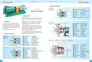
  • 1. Structure and material Pump housing Impeller Mouth ring Seal ring Spacer sleeve Bearing External magnet Fluoroplastic Alumina ceramic Fluorubber /1Cr18Ni9Ti Fill Fluoroplastics alloy/Permanent magnet Polyethylene / Permanent magnet Pump housing Impeller Mouth ring Bearing Main shaft Seal ring Media axis socket Spacer sleeve Rotor Stainless cap Bracket External magnet HT200 lined by Fluoroplastics alloy Alumina ceramic Fill Alumina ceramic Fluorubber / Fluoroplastic Fluoroplastic / FeB 1Cr18Ni9Ti Ht200 HT200 NdFeB Pump housing Impeller Impeller nut Mouth ring Seal ring Pump cover Spacer sleeve Rotor Main shaft External magnet Bracket HT200 lined by Fluoroplastic Fill Alumina ceramic Fluorubber HT200 F46/ NdFeB Silicon carbide HT200 NdFeB Ht200 F46/Reinforced carbon fibre 1 2 The products are widely applicable to: petrochemical industry, acid or base making, non- ferrous metal metallurgy, acid-cleaning technique in car-manufacturing, rare earth separation, pesticides, dyes, medicines, papermaking, galvanization, and radio industry, etc. Service temperature: -20 ~100 .℃ ℃ Application Magnetic Pump Series Leak-proof design Operating principle Strong and sturdy pump housing No shaft seal. Utilize magnetic coupling indirect driving, which free you from the leak problem and will not contaminate the site. Because the pump's liquid carrying part is made of Fluoroplastic alloy it can continually carry acid, base, or strong oxidizer at any concentration without any damage. In the driving device the initiative magnet junction box is directly installed onto the motor shaft. The pump chamber is totally sealed, and is propelled to rotate by the magnetic impeller on the magnetic coupling indirect driving pump shaft, its structure tight, safe, and energy-saving. Though the liquid-touching part is made of fluoroplastics, the pump enclosure is made of metal, so the pump can sustain the pipe's weight and mechanical shock. Design feature Structure and material Pump housing Seal ring Bearing Impeller Main shaft Thrust plate Spacer sleeve External magnet Fluoroplastic Fluorubber / High-density carbon Fluoroplastic Alumina ceramic High-density carbon Fluoroplastics Permanent magnet Pump housing Auxiliary impeller Seal ring Impeller Main shaft Mouth ring Bearing Gasket Spacer sleeve External magnet Fluoroplastic Fluoroplastic Fluorubber / 45# Steel, Alumina ceramic Alumina ceramic Fluorubber / F46/1Cr18Ni9Ti Permanent magnet Fluoroplastics alloy/Permanent magnet Structure and material WOLONG WOLONG PTFE PTFE PTFE PTFE FEP PTFE FEP PTFE PTFE FEP cast iron FEP PTFE cast iron lining PTFE cast iron
  • 2. CQB16-12-50F CQB15-15-65F CQB20-15-75F CQB25-20-100F CQB32-20-110F CQB40-40-100F CQB50-32-125F CQB40-40-125F Applicable model: Applicable model: Applicable model: 1 CQB16-12-50F *0.6 2 8 0.8 1.5 10 9.0 16×12 2900 0.025 5 2 CQB15-15-65F 3 CQB20-15-75F 4 CQB25-20-100F 5 CQB32-20-110F *0.8 3.2 16 1 2.8 18 1 7 20 *1.6 7 22 1 10.5 25 *2.5 10.5 28 4 13.5 30 *5.5 13 35 6.0 15×15 2900 0.180 7 6.0 20×15 2900 0.180 8 6.0 25×20 2900 0.370 12 6.0 32×20 2900 0.550 18 6 CQB40-25-120F 7 CQB40-40-100F 8 CQB40-40-125F 9 CQB50-32-125F 10 CQB50-32-125FA 11 CQB50-32-160FA 12 CQB50-32-200FA 13 CQB65-50-150F 14 CQB65-50-160F 15 CQB65-50-180F 16 CQB65-50-160FL 17 CQB65-40-200FA 18 CQB80-65-160FA 19 CQB80-50-200FA 20 CQB100-80-160FL 4 15 36 5.0 40×25 2900 0.750 35*6.3 15 42 8 12 42 4 11 38 5.0 40×40 2900 0.550 20*6 11 43 8 9 45 4 19 35 3.7 40×40 2900 1.1 40*6.5 17.5 42 9 16 40 7 22 28 3.5 50×32 2900 1.5 45*12 20 42 15 19 46 7 22 28 3.5 50×32 2900 2.2 105*12.5 20 42 15 19 46 7 33 30 3.5 50×32 2900 4.0 140*12.5 32 39 15 29 41 7 52 20 3.5 50×32 2900 7.5 210*12.5 50 31 15 48 35 15 26 40 4.0 65×50 2900 4.0 100*20 25 48 25 24 52 15 32 38 4.0 65×50 2900 4.0 100*17.5 32 40 20 29 47 6 37 22 4.0 65×50 2900 5.5 120*8 36 28 10 33 30 15 33 41 4.0 65×50 2900 7.5 210*25 32 51 30 29 55 15 51 41 4.0 65×40 2900 11.0 250*25 50 48 30 49 54 35 34 45 4.0 80×65 2900 11.0 285*50 32 60 60 28 52 35 52 50 4.0 80×50 2900 18.5 320*50 50 60 60 45 60 70 34 53 5.0 100×80 2900 18.5 300*100 32 58 120 30 60 3 4 1 2 4 6 8 10 20 15 10 5 3 40-40-125 40-25-120 32-20-110 40-40-10025-20-100 20-15-75 15-15-65 m 3 m /h H Q 16-12-50 8 10 15 20 30 50 80 100 120 m 3 m /h Q H 50 30 20 10 50-32-200 65-50-180 50-32-160 50-32-125(L) 65-40-200 65-50-160(L) 65-50-150 80-50-200 80-65-160 100-80-160 3 m /h m % m mm r/min kw kg Number Model Flow rate Pump lift Efficiency Net positive suction head Inlet×Outlet Rotational speed Power of motor Weight of complete machine Model and parameter Note: 1. * stands for standard specifications; please choose parameters the same as or similar to what are in the table as much as possible, and if the parameters are not included in the table, our factory can realize them by improving the impeller. 2. If the status point flow rate is too small, the inlet should be connected to the return pipe, and for more specific information you can consult the company's technical department. Performance curve diagram CQB Magnet Pump (Figure 1) CQB Magnet Pump (Figure 2) The medium is clear water(20℃) The medium is clear water(20℃) CQB65-50-160FL(A) CQB 65 50 160 F L A Model meaning Centrifugal pump drived by CQB magnet The pump's inlet diameter is 65mm The inlet diameter is 50mm The impeller's norminal diameter is 160mm It means the long bracket with underplate It means distinction code The material of the liquid carrying part is fluoroplastic alloy Pictures of some products WOLONG WOLONG
  • 3. 5 6 L S P f W T H h a g x CQB16-12-50F CQB15-15-65F CQB20-15-75F CQB25-20-100F 200 56 80 30 90 71 100 45 24 17 22 290 71 115 40 112 90 125 2056 20 25 316 71 120 55 112 90 138 56 27 20 38 360 80 150 60 125 100 165 63 34 26 49 430 435 510 430 65 50 85 65 60 67 76 60 CQB32-20-110F CQB40-25-120F CQB50-32-125F CQB40-40-100F 200 270 225 200 125 65 65 125 148 175 192 148 115 150 158 115 216 244 268 216 105 113 128 105 120 140 130 130 90 90 100 100 120 100 130 100 65 75 90 100 4-φ13 4- M12 4-φ13 4-φ13 4-φ11 4-φ11 4-φ11 4-φ13 4-φ12 4-φ12 4-φ13 4-φ12 n-φd n-φt n-φD n-φd n-φt CQB50-32-125FA CQB50-32-160FA CQB50-32-200FA CQB65-50-160FL CQB65-40-200FA CQB80-65-160FA CQB80-50-200FA CQB100-80-160FL 950 1025 1040 1180 1305 1420 1035 1255 895 920 990 1130 1160 1160 990 1130 590 590 650 720 730 730 650 720 75 100 90 105 130 130 170 130 80 80 80 80 100 100 80 100 395 390 450 500 480 480 150 485 352 392 440 440 420 440 392 500 212 232 260 260 240 240 232 280 24 24 25 24 24 24 24 24 165 165 165 185 200 200 185 220 125 125 125 145 160 160 145 180 100 100 100 110 145 125 125 160 330 330 380 435 430 430 380 435 140 140 140 150 185 165 165 200 4-φ18 4-M16 4- M16 4- M16 4- M16 8- M16 4- M16 8- M16 4- M16 4-φ18 4-φ18 4-φ18 4- M16 8- M16 8-φ18 8- M16 IMD40-25-165FA IMD50-40-165F IMD65-50-130F IMD80-65-140F IMD80-65-140F IMD100-80-180F Dimension diagram for installation Table 1: Model Applicable model: (For dimension see table 1) Applicable model: (For dimension see diagram) Applicable model: (For dimension see diagram) (For dimension see table 2)Applicable model: CQB50-32-125FA CQB65-40-200FA CQB50-32-160FA CQB80-65-160FA CQB50-32-200FA CQB80-50-200FA CQB65-50-160FL CQB100-80-160FL Applicable model: (For dimension see table 3) Table 2: Model Table 3: Model The IMD series magnetic drive pump is without shaft seal and utilizes the magnetic coupling indirect driving, totally eliminating leakage. The IMD series magnetic drive pump employs separation sleeve made of the state-of-the-art materials and has high-strength mechanical property, eliminating the magnetic eddy current phenomenon of general magnetic pump. The IMD series magnetic drive pump employs the exclusive pull-back structure, and a single person can easily conduct inner inspection and component changing, with no need to disassemmble the pipes, wich greatly helps daily inspection and maintaining work. Magnetic pump series Application 3IMD series magnetic pump, flow rate: 1~160 m /h; pump lift: 17~62m, applicable to the carrying of caustic, inflammable, explosible, toxic, or volatile chemical mediums. Service temperature: -20 ~100 . Idle running is forbidden.℃ ℃ Design feature Structure and materials Pump housing seal ring Impeller Pump housing mouth ring Impeller nut Main shaft Shaft spacer seal ring Pump housing Pump cover bearing Rotary assembly Spacer sleeve assembly External manget Bracket Fluorubber Fluoroplastic alloy Silicon nitride Fill F4 Silicon carbide Fluorubber HT200 lined with F46 HT200 lined with F46 Fill F4 F46 /NdFeB HT200 /NdFeB HT200 F46 / Reinforced carbon fibere Pump housing seal ring Impeller Pump housing mouth ring Impeller nut Main shaft Shaft spacer seal ring Pump housing Pump cover bearing Rotary assembly Spacer sleeve assembly External manget Bracket Pedestal Fill F4 Fluoroplastic alloy Silicon carbide Fill F4 Silicon carbide Fill F4 HT200 lined with F46 Fluoroplastic alloy Fill F4 F46 /NdFeB HT200 /NdFeB HT200 F46 / Reinforced carbon fibere HT200 WOLONG WOLONG
  • 4. 1 IMD40-25-130FA 2 IMD40-25-140FA 3 IMD40-25-150FA 4 IMD40-25-160FA 5 IMD40-25-165FA 6 IMD40-25-170FA 7 IMD40-25-185F 8 IMD40-25-230F 9 IMD50-40-140F 10 IMD50-40-150F 11 IMD50-40-160F 12 IMD50-40-165F 13 IMD50-32-200F 14 IMD50-32-195F 15 IMD65-50-120 16 IMD65-50-130F 17 IMD65-50-165F 18 IMD65-40-200F 20 21 40 4.0 65×50 2900 5.5 13530 15 50 35 12 50 20 20 45 4.0 65×50 2900 5.5 13530 19 55 35 17 56 20 35 40 4.0 65×50 2900 7.5 14530 33 54 35 30 52 15 52 25 4.0 65×40 2900 1125 50 37 35 45 42 8 37 23 3.5 50×40 2900 5.5 14015 36 36 20 33 39 8 40 28 3.5 50×40 2900 5.5 14015 39 40 20 36 43 7 52 20 3.5 50×32 2900 7.512.5 50 31 15 47 38 5 51 25 3.5 50×32 2900 7.57 50 28 10 48 33 0.7 39 25 3.0 40×25 2900 3 851 39 28 2 38 28 4 62 15 3.0 40×25 2900 7.5 1706 60 20 10 57 32 8 28 27 3.5 50×40 2900 5.5 14015 26 40 20 23 41 8 32 25 3.5 50×40 2900 5.5 14015 30 38 20 27 39 4 21 25 3.0 40×25 2900 3 856 20 32 8 18 33 4 27 25 3.0 40×25 2900 3 856 26 32 8 24 33 4 31 25 3.0 40×25 2900 3 856 30 32 8 28 33 4 35 25 3.0 40×25 2900 3 856 34 31 8 32 32 4 37 25 3.0 40×25 2900 3 856 36 29 8 34 30 4 40 25 3.0 40×25 2900 4 906 39 28 8 36 29 7 8 19 IMD80-65-120F 20 IMD80-65-140F 21 IMD80-50-200F 22 IMD100-80-160F 23 IMD100-80-180F 24 IMD125-100-160F 25 IMD125-100-200F 35 19 35 4.0 80×65 2900 1160 17 51 70 13 48 35 28 35 4.0 80×65 2900 1160 25 46 70 22 46 35 52 50 4.0 80×50 2900 18.550 50 55 60 45 56 60 34 50 5.0 100×80 2900 30100 32 60 120 27 62 60 42 50 5.0 100×80 2900 30100 40 60 120 35 62 80 22 50 6.0 125×100 2900 30120 20 56 140 15 56 100 40 50 6.0 125×100 2900 37120 37 56 160 32 56 10 20 30 40 50 60 105 15 20 30 40 50 60 100 130 160 200 40-25-230 50-32-200 65-40-200 80-50-200 50-40-165 50-40-160 40-25-165 40-25-150 65-50-165 80-65-140 65-50-130 80-65-120 100-80-180 100-80-160 125-100-200 125-100-160 m 3 m /h 5 15 Q H Models and Parameters 3 m /h m % m mm r/min kw kg ModelNumber Flow rate Pump lift Efficiency Net positive suction head Inlet×Outlet Rotational speed Power of motor Weight of complete machine Models and Parameters 3 m /h m % m mm r/min kw kg ModelNumber Flow rate Pump lift Efficiency Net positive suction head Inlet×Outlet Rotational speed Power of motor Weight of complete machine Note: 1. * stands for standard specifications; please choose parameters the same as or similar to what are in the table as much as possible, and if the parameters are not included in the table, our factory can realize them by improving the impeller. 2. If the status point flow rate is too small, the inlet should be connected to the return pipe, and for more specific information you can consult the company's technical department. IMD80-65-140F(A) IMD 80 65 140 F A Model meaning Centrifugal pump drived by IMD magnet The pump's inlet diameter is 80mm The pump's outlet diameter is 65mm The impeller's norminal diameter is 140mm The material of the liquid carrying part is fluoroplastic alloy It means distinction code The medium is clear water(20℃) Performance curve diagram IMD Magnet Pump WOLONG WOLONG 170 Including base 170 Including base 300 Including base 300 Including base 300 Including base 335 Including base 435 Including base 435 Including base 660 Including base 680 Including base
  • 5. 165 125 22 140 100 20 4-M16 4-M16 165 125 22 140 100 20 4-M16 4-M16 4- 20 4- 20 185 145 22 150 110 22 4-M16 4- 20 200 160 22 185 145 22 4-M16 4- 204- 18 200 160 22 185 145 22 4-M16 4- 204- 18 200 160 22 165 125 22 4-M16 4- 208- 18 220 180 24 200 160 24 8-M16 4- 258- 18 220 180 24 160 24 8-M16 4- 258- 18 250 210 24 225 180 24 8-M16 4- 258- 18 25 25 40 40 40 40 50 50 50 4- 18 150 110 20 115 85 18 4-M16 4-M12 4- 2025 250 210 24 225 180 24 8-M16 4- 258- 1850 610IMD40-25-130FA 250 70 80 210 160 310 150 150 110 20 115 85 18 4-M16 4-M12 4- 15 610IMD40-25-140FA 250 70 80 210 160 310 150 150 110 20 115 85 18 4-M16 4-M12 4- 15 610IMD40-25-150FA 250 70 80 210 160 310 150 150 110 20 115 85 18 4-M16 4-M12 4- 15 610IMD40-25-160FA 250 70 80 210 160 310 150 150 110 20 115 85 18 4-M16 4-M12 4- 15 610IMD40-25-165FA 250 70 80 210 160 310 150 150 110 20 115 85 18 4-M16 4-M12 4- 15 610IMD40-25-170FA 250 70 80 210 160 310 150 150 110 20 115 85 18 4-M16 4-M12 4- 15 610IMD40-25-185F 250 70 80 210 160 310 150 150 110 20 115 85 18 4-M16 4-M12 4- 15 730IMD50-40-140F 330 70 80 265 212 360 180 165 125 20 150 110 20 4-M16 4-M16 4- 15 730IMD50-40-150F 330 70 80 265 212 360 180 165 125 20 150 110 20 4-M16 4-M16 4- 15 730IMD50-40-160F 330 70 80 265 212 360 180 165 125 20 150 110 20 4-M16 4-M16 4- 15 730IMD50-40-165F 330 70 80 265 212 360 180 165 125 20 150 110 20 4-M16 4-M16 4- 15 730IMD50-32-195F 330 70 90 265 212 365 180 165 125 22 140 100 20 4-M16 4-M16 4- 15 730IMD50-32-200F 330 70 90 265 212 365 180 165 125 22 140 100 20 4-M16 4-M16 4- 15 725IMD65-50-130F 318 95 80 265 212 360 180 185 20 165 125 20 4-M16 4- 154- 18 730IMD65-50-165F 318 95 80 265 212 365 180 145 24 165 125 24 4-M16 4-M16 4- 15 928IMD65-40-200F 410 70 100 290 220 430 230 185 185 145 22 150 110 22 4-M16 4- 154- 18 935IMD80-65-120F 416 70 100 290 220 430 230 200 160 22 185 145 22 4-M16 4- 154- 18 935IMD80-65-140F 416 70 100 290 220 430 230 200 160 22 185 145 22 4-M16 4- 15 4- 18 970IMD80-50-200F 398 70 100 320 240 445 230 160 22 165 125 22 4-M16 4- 15 8- 18 1110IMD100-80-160F 485 95 125 345 280 500 250 200 220 180 24 160 24 8-M16 4- 158- 18 1110IMD100-80-180F 485 95 125 345 280 500 250 220 180 24 200 200 160 24 8-M16 4- 158- 18 1110IMD125-100-160F 490 95 125 345 280 500 250 250 210 24 225 180 24 8-M16 4- 158- 18 730IMD40-25-230F 336 70 100 275 212 370 180 150 110 20 115 85 18 4-M16 4-M12 4- 15 1 2 3 4 5 6 7 8 9 10 11 12 13 14 15 16 17 18 19 20 21 22 23 725IMD65-50-120F 318 95 80 265 212 360 180 185 145 145 20 165 125 20 4-M16 4- 154- 18 24 25 1110IMD125-100-200F 490 95 125 345 280 500 250 250 210 24 225 180 24 8-M16 4- 158- 18 L S P f W T H h a b e g i j n- t n- d n- q 710 710 950 950 950 950 1090 1090 1090 710 1090 340 340 490 490 490 490 525 525 525 340 525 310 310 440 440 440 440 475 475 475 310 475 425 425 510 510 510 525 595 595 595 425 595 240 240 310 310 310 310 345 345 345 240 345 90 90 100 100 100 100 125 125 125 90 125 745IMD50-32-195F 530 745IMD50-32-200F 530 36 1000IMD65-40-200F 740 5 1000IMD80-65-120F 740 5 1000IMD80-65-140F 740 5 1000IMD80-50-200F 740 5 1170IMD100-80-160F 870 30 IMD100-80-180F 870 30 IMD125-100-160F 870 30 36 745IMD40-25-230F 530 36 2 3 4 5 6 7 8 9 10 11 IMD125-100-200F 870 30 L S P f W T H h a b e g i j n- t n- d n- q 1 B r 200 9 10 4- q 1170 1170 1170 Installation dimension Without pedestal (Table 1) With pedestal (Table 2) Table 1 Table 2 ModelNumber The ZMD series self-priming magnetic pump amply combines the excellent features of both the self-priming pump and the magnetic pump, and it has both the self- priming property and do away with shafting seal, and it utilizes the magnetic coupling indirect driving, totally eliminating leakage. The ZMD series magnetic drive pump employs separation sleeve made of the state-of-the-art materials and has high-strength mechanical property, eliminating the magnetic eddy current phenomenon of general magnetic pump. The ZMD series magnetic drive pump employs the exclusive pull-back structure, and a single person can easily conduct inner inspection and component changing, with no need to disassemmble the pipes, wich greatly helps daily inspection and maintaining work. Self-priming magnetic pump series Design feature Application ZMD series magnetic pump is widely applicable to industries like petrochemicals, non-ferrous metal metallurgy, pesticide, acid and base making, papermaking, acid washing technics, rare earth seperation, galvanization, electronics, etc., and its structure is the most novel among the current magnetic pump varieties. It is highly-efficient, energy-conserving, safe, and practical. Structure and materials Pump housing Pump cover Impeller front mouth-ring Pump cover mouth-ring Impeller nut Main shaft Pump mouth-ring Impeller rear mough-ring Impeller Front cover Outlet flang Front bearing Spacer sleeve seal ring Spacer sleeve assembly Rotary assembly Rear bearing External magnet Bracket HT200 lined with HT200 lined with Fill Silicon carbide Fill Silicon carbide Silicon carbide Fill Fluoroplastic HT200 lined with HT200 lined with Fill Fluorubber / Reinforced carbon /NdFeB Fill HT200 /NdFeB HT200 WOLONG WOLONG FEP FEP PTFE PTFE PTFE FEP FEP PTFE FEP FEP PTFE
  • 6. 1 40ZMD-32F 2 50ZMD-32F 3 50ZMD-45F 4 65ZMD-32F 5 65ZMD-45F 6 80ZMD-32F 7 80ZMD-45F 3 6 10 8 15 20 8 12.5 15 20 30 35 20 25 35 35 60 65 35 50 60 34 32 28 34 32 28 49 48 47 34 32 28 45 45 40 34 32 28 46 45 40 16 24 20 25 44 44 21 35 40 40 52 48 40 44 53 50 55 50 38 50 48 3.0 3.0 3.0 3.5 4.5 3.5 4.5 40×25 50×50 50×50 65×50 65×40 80×65 80×50 3 3 3 3 3 3 3 150 180 180 200 200 200 200 2900 2900 2900 2900 2900 2900 2900 4 5.5 7.5 7.5 11 11 18.5 125 180 170 200 290 280 320 * * * * * * * m 3 m /h Q H 65ZMD-32F 65ZMD-45F 40ZMD-32F 50ZMD-32F 50ZMD-45F 80ZMD-45F 80ZMD-32F 50 40 30 20 6 10 15 20 25 30 40 50 60 70 11 12 2 3 4 5 6 7 1 L S P f W T H h a b c e i jn-φdk g n-φtq 40ZMD-32F 50ZMD-32F 50ZMD-45F 65ZMD-32F 65ZMD-45F 80ZMD-32F 80ZMD-45F 756 905 875 903 1110 1180 336 318 354 275 410 412 416 70 95 95 70 70 75 70 215 172 165 145 218 220 225 225 230 185 225 255 265 265 265 240 290 2 9 0 290 212 212 212 190 220 2 2 0 220 510 496 495 450 610 534 330 320 320 270 400 380 φ150 φ165 φ165 φ185 φ185 φ200 φ200 φ110 φ125 φ125 φ145 φ145 φ160 φ160 50 50 65 40 65 80 80 4-φ18 4-φ18 4-φ18 4-φ18 4-φ18 8-φ18 8-φ18 20 20 20 20 20 20 20 φ115 φ165 φ165 φ165 φ150 φ185 φ185 φ85 φ125 φ125 φ125 φ110 φ145 φ145 50 50 50 25 40 65 65 20 18 18 18 18 20 20 4-φ15 4-φ18 4-φ18 4-φ18 4-φ18 4-φ18 4-φ181150 244 245 618 450 3 4 0 2 8 0 4- 15 X X 90 100 105 98 114 115 120 3 m /h m % m mm r/min kw kgm s Models and Parameters ModelNumber Flow rate Pump lift Effici -ency Net positive suction head Inlet×Outlet Rotational speed Power of motor Weightof completemachine Note: 1. * stands for standard specifications; please choose parameters the same as or similar to what are in the table as much as possible, and if the parameters are not included in the table, our factory can realize them by improving the impeller. 2. If the status point flow rate is too small, the inlet should be connected to the return pipe, and for more specific information you can consult The company's technical department. Performance curve diagram The medium is clear water(20℃) ZMD self-priming magnetic pump 50ZMD-32F ZMD 50 32 F Model meaning The pump's inlet diameter is 50mm self-priming manetic drive pump 32m The pump lift is 32m. The material of the liquid carrying part is fluoroplastic alloy Installation dimension figure Inlet flange Outlet flange Number Model Notes on the use of ZMC self-priming magnetic pump, FZB self-priming pump Installation instructions and connection requirements Make the concrete foundation according to basic dimensions, and simultaneously bury in the foundation bolt. Put the machine assembly on the foundation and make sure the pump is level, then tighten the foundation bolt. The pump should be near the water tank as much as possible. The diameter of the pump's liquid inlet duct should not be larger than what is required, and the length of the liquid inlet duct should not be more than 5m, the smaller the better but also under the requirements. A filter net should be installed at the bottom of the liquid inlet duct, so as to prevent large pellets or litter from entering into the pump housing and damaging the impeller or affecting the pump's running, and the filtering area should be 3 to 4 times larger than the section area of the duct. A value must be installed in the pipeline of the pump's liquid outlet duct to adjust the flow rate, as that the pump works under the specified flow rate, avoiding the inoperation of the pump due to overflowing. The diameter of the liquid outlet duct should not be smaller than what is specified, the larger the better but also under the requirements. The length of the liquid outlet duct must be larger than 1.5 times of the length of the liquid inlet duct, the longer the better if possible. The weight of the liquid inlet and outlet duct should not be relied on the inlet and outlet flanges, and they should be fixed on their own brackets. The connection parts of the liquid inlet and outlet duct should be tight and air-proof, or else the self-priming function and the pump's normal running will be affected. 1. 2. 3. 4. Directions for use and maintenance instructions The transporting of solid particles or easy-to-crystallize mediums by the self-priming magnetic pump is forbidden. It is not permitted to run continuously with the discharge outlet closed, and the lowest flow rate should be kept. While installing ducts, first install the inlet duct, after fill liquid fully install the outlet duct. After installation, plug in the the power and check whether the running of the pump is smooth by the point-action way, and check whether the rotation direction of the electric motor is the same as the change of direction label. Open about one-third of the outlet valve, then start the self-priming pump (by open the valve), after that slowly adjust the outlet valve until the pump reaches the specified flow range. 5. When carrying the liquid, the flow rate, pump lift and the self-priming height should be within the specified range, and the margin should not be too large, or else there will be empty-sucking, which will cause the pump to be out of order. There should be no empty-sucking situation while the self-priming pump is running. Once empty-sucking situation occurs, liquid must be conducted before renew self-priming. Therefore, the user must have facilities to control the lowest liquid postion or employ someone to take care of it, so as to prevent the mediums in the water tank from being sucked empty. The self-priming pump cannot carry mediums which will produce many bubbles, and it cannot transport mediums which are mixture of air and liquid. While transporting easy-to-crystallize mediums, if the pump is not in use for some time, the pump chamber should be cleaned, and not crystallized mediums should ramain, so as to prevent damage on the pump when it is started again due to the drystallization; While restart the pump, liquid should be conducted in according to requirements before self-priming. 9. When carrying generel no-crystal mediums, if the pump is restarted after a long period of no use, before restarting, it should be check that whether the liquid in the pump is enough. If not enough, fill it fully before self-priming. While the pump is placed liquid level in using or if it replaces the duct pump in using, the air valve or cushion valve should not be attached. If so, discharge the air valve or the cushion valve. The outlet duct of the pump should not be installed with check valve. If so, an air-bleed hole should be placed at the lower end of the check valve. The installation height for self-priming height is as follows: 3m for self-priming in clear water / density of the medium = actual self-priming height. 1. 2. 3. 4. 5. 6. 7. 8. 9. 10. 11. 12. WOLONG WOLONG self-absorption time Self-absorption height