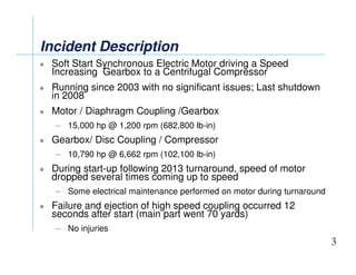
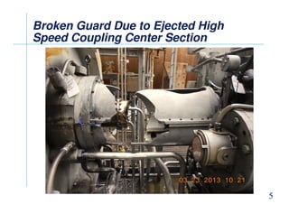
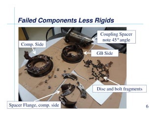
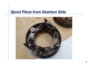
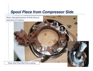
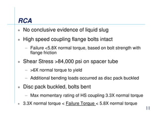
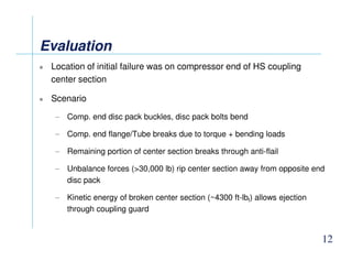
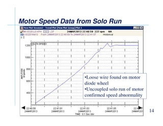
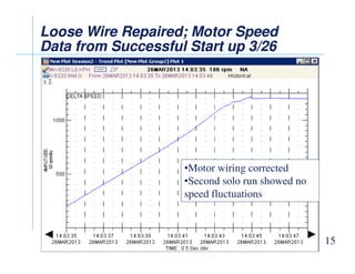
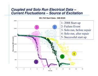
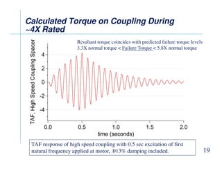
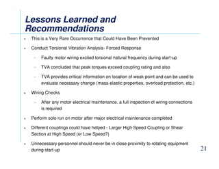
COUPLING FAILURE DUE TO A MOTOR FAULT
COUPLING FAILURE DUE TO
A MOTOR FAULT
A MOTOR FAULT
Clay McClinton
Rotating Equipment Reliability Analyst, Chevron
Dan Phillips
Manager Global Field Services, Kop-Flex
Joe Corcoran
Manager Global Services & Training, Kop-Flex
Incident Description
 Soft Start Synchronous Electric Motor driving a Speed
Increasing Gearbox to a Centrifugal Compressor
 Running since 2003 with no significant issues; Last shutdown
in 2008
 Motor / Diaphragm Coupling /Gearbox
– 15,000 hp @ 1,200 rpm (682,800 lb-in)
Gearbox/ Disc Coupling / Compressor
3
 Gearbox/ Disc Coupling / Compressor
– 10,790 hp @ 6,662 rpm (102,100 lb-in)
 During start-up following 2013 turnaround, speed of motor
dropped several times coming up to speed
– Some electrical maintenance performed on motor during turnaround
 Failure and ejection of high speed coupling occurred 12
seconds after start (main part went 70 yards)
– No injuries
Motor Speed Data from LS Speed
Pick
Pick-
-up
up
Motor Speed Data from LS Speed
Pick
Pick-
-up
up
4
Speed Abnormality
Broken Guard Due to Ejected High
Speed Coupling Center Section
Broken Guard Due to Ejected High
Speed Coupling Center Section
5
Failed Components Less
Failed Components Less Rigids
Rigids
Failed Components Less
Failed Components Less Rigids
Rigids
Comp. Side
GB Side
Coupling Spacer
note 45°angle
6
Spacer Flange, comp. side
Disc and bolt fragments
Spool Piece from Gearbox Side
7
Spool Piece from Compressor Side
Note: threaded portion of bolts bent in
direction of rotation
8
Note Anti-Flail Did Not Contain
Driving End of Spacer with “Nut
Broaching”
Broaching”
Driving End of Spacer with “Nut
Broaching”
Broaching”
9
Nut/bolt pulled through flange
Waterfall Plot from Start Up Reveals
6.9 Mils @ 11.25 Hz
6.9 Mils @ 11.25 Hz
Waterfall Plot from Start Up Reveals
6.9 Mils @ 11.25 Hz
6.9 Mils @ 11.25 Hz
Data from gearbox 6X radial probe, low speed side
10
Prior to shutdown, radial vibration was 0.5mils p-p
RCA
RCA
RCA
RCA
 No conclusive evidence of liquid slug
 High speed coupling flange bolts intact
– Failure 5.8X normal torque, based on bolt strength with
flange friction
 Shear Stress 84,000 psi on spacer tube
11
 Shear Stress 84,000 psi on spacer tube
– 6X normal torque to yield
– Additional bending loads occurred as disc pack buckled
 Disc pack buckled, bolts bent
– Max momentary rating of HS coupling 3.3X normal torque
 3.3X normal torque  Failure Torque  5.8X normal torque
Evaluation
Evaluation
Evaluation
Evaluation
 Location of initial failure was on compressor end of HS coupling
center section
 Scenario
– Comp. end disc pack buckles, disc pack bolts bend
– Comp. end flange/Tube breaks due to torque + bending loads
12
– Comp. end flange/Tube breaks due to torque + bending loads
– Remaining portion of center section breaks through anti-flail
– Unbalance forces (30,000 lb) rip center section away from opposite end
disc pack
– Kinetic energy of broken center section (~4300 ft-lbf) allows ejection
through coupling guard
Evaluation
Evaluation
Evaluation
Evaluation
 Low speed coupling looked good visually
– Replaced as precautionary measure. Further inspection
revealed no defects.
 Low speed coupling had higher torque capacity ratio
 Max Momentary Torque was 8X vs. 3.2X
 Not typical
13
 Not typical
 Original Selection was a MAX-C Elastomeric Coupling
 So what caused the tremendous loads?
 Speed fluctuations investigated
 Torsional analysis reviewed
Motor Speed Data from Solo Run
14
•Loose wire found on motor
diode wheel
•Uncoupled solo run of motor
confirmed speed abnormality
Loose Wire Repaired; Motor Speed
Data from Successful Start up 3/26
Loose Wire Repaired; Motor Speed
Data from Successful Start up 3/26
15
•Motor wiring corrected
•Second solo run showed no
speed fluctuations
Coupled and Solo Run Electrical Data
Coupled and Solo Run Electrical Data –
–
Current Fluctuations
Current Fluctuations –
– Source of Excitation
Source of Excitation
Coupled and Solo Run Electrical Data
Coupled and Solo Run Electrical Data –
–
Current Fluctuations
Current Fluctuations –
– Source of Excitation
Source of Excitation
3 2
2
1- 2008 Start-up
2- Failure Event
3- Solo run, before repair
4- Solo run, after repair
5- Successful start up
16
4
1
5- Successful start up
5
5
Verification of
Verification of Torsional
Torsional Analysis
Analysis
Verification of
Verification of Torsional
Torsional Analysis
Analysis
 Original torsional analysis reviewed
– Frequency (11.25 Hz) of high radial vibrations found
during start-up prior to failure appeared to be near a
system torsional natural frequency
 New forced response analysis conducted
17
 New forced response analysis conducted
– Wiring problem caused current fluctuations in motor,
exciting torsional natural frequency
– Need to determine effect of short duration torsional
excitation at motor, resulting from diode wheel wiring
Campbell Diagram
Campbell Diagram –
– 1
1st
st Torsional
Torsional Mode at
Mode at
11.9 Hz (719 CPM)
11.9 Hz (719 CPM)
Campbell Diagram
Campbell Diagram –
– 1
1st
st Torsional
Torsional Mode at
Mode at
11.9 Hz (719 CPM)
11.9 Hz (719 CPM)
18
Calculated Torque on Coupling During
~4X Rated
~4X Rated
Calculated Torque on Coupling During
~4X Rated
~4X Rated
Resultant torque coincides with predicted failure torque levels
3.3X normal torque  Failure Torque  5.8X normal torque
19
TAF response of high speed coupling with 0.5 sec excitation of first
natural frequency applied at motor, .013% damping included.
Vibration Data from Successful Start
Vibration Data from Successful Start-
-
up 3/26
up 3/26
Vibration Data from Successful Start
Vibration Data from Successful Start-
-
up 3/26
up 3/26
20
Lessons Learned and
Lessons Learned and
Recommendations
Recommendations
Lessons Learned and
Lessons Learned and
Recommendations
Recommendations
 This is a Very Rare Occurrence that Could Have Been Prevented
 Conduct Torsional Vibration Analysis- Forced Response
– Faulty motor wiring excited torsional natural frequency during start-up
– TVA concluded that peak torques exceed coupling rating and also
– TVA provides critical information on location of weak point and can be used to
evaluate necessary change (mass-elastic properties, overload protection, etc.)
21
evaluate necessary change (mass-elastic properties, overload protection, etc.)
 Wiring Checks
– After any motor electrical maintenance, a full inspection of wiring connections
is required
 Perform solo run on motor after major electrical maintenance completed
 Different couplings could have helped - Larger High Speed Coupling or Shear
Section at High Speed (or Low Speed?)
 Unnecessary personnel should never be in close proximity to rotating equipment
during start-up

....................Coupling Failure.pdf

  • 1.
    COUPLING FAILURE DUETO A MOTOR FAULT COUPLING FAILURE DUE TO A MOTOR FAULT COUPLING FAILURE DUE TO A MOTOR FAULT COUPLING FAILURE DUE TO A MOTOR FAULT
  • 2.
    COUPLING FAILURE DUETO COUPLING FAILURE DUE TO A MOTOR FAULT A MOTOR FAULT Clay McClinton Rotating Equipment Reliability Analyst, Chevron Dan Phillips Manager Global Field Services, Kop-Flex Joe Corcoran Manager Global Services & Training, Kop-Flex
  • 3.
    Incident Description Incident Description IncidentDescription Incident Description Soft Start Synchronous Electric Motor driving a Speed Increasing Gearbox to a Centrifugal Compressor Running since 2003 with no significant issues; Last shutdown in 2008 Motor / Diaphragm Coupling /Gearbox – 15,000 hp @ 1,200 rpm (682,800 lb-in) Gearbox/ Disc Coupling / Compressor 3 Gearbox/ Disc Coupling / Compressor – 10,790 hp @ 6,662 rpm (102,100 lb-in) During start-up following 2013 turnaround, speed of motor dropped several times coming up to speed – Some electrical maintenance performed on motor during turnaround Failure and ejection of high speed coupling occurred 12 seconds after start (main part went 70 yards) – No injuries
  • 4.
    Motor Speed Datafrom LS Speed Motor Speed Data from LS Speed Pick Pick- -up up Motor Speed Data from LS Speed Motor Speed Data from LS Speed Pick Pick- -up up 4 Speed Abnormality
  • 5.
    Broken Guard Dueto Ejected High Broken Guard Due to Ejected High Speed Coupling Center Section Speed Coupling Center Section Broken Guard Due to Ejected High Broken Guard Due to Ejected High Speed Coupling Center Section Speed Coupling Center Section 5
  • 6.
    Failed Components Less FailedComponents Less Rigids Rigids Failed Components Less Failed Components Less Rigids Rigids Comp. Side GB Side Coupling Spacer note 45°angle 6 Spacer Flange, comp. side Disc and bolt fragments
  • 7.
    Spool Piece fromGearbox Side Spool Piece from Gearbox Side Spool Piece from Gearbox Side Spool Piece from Gearbox Side 7
  • 8.
    Spool Piece fromCompressor Side Spool Piece from Compressor Side Spool Piece from Compressor Side Spool Piece from Compressor Side Note: threaded portion of bolts bent in direction of rotation 8 Note Anti-Flail Did Not Contain
  • 9.
    Driving End ofSpacer with “Nut Driving End of Spacer with “Nut Broaching” Broaching” Driving End of Spacer with “Nut Driving End of Spacer with “Nut Broaching” Broaching” 9 Nut/bolt pulled through flange
  • 10.
    Waterfall Plot fromStart Up Reveals Waterfall Plot from Start Up Reveals 6.9 Mils @ 11.25 Hz 6.9 Mils @ 11.25 Hz Waterfall Plot from Start Up Reveals Waterfall Plot from Start Up Reveals 6.9 Mils @ 11.25 Hz 6.9 Mils @ 11.25 Hz Data from gearbox 6X radial probe, low speed side 10 Prior to shutdown, radial vibration was 0.5mils p-p
  • 11.
    RCA RCA RCA RCA No conclusiveevidence of liquid slug High speed coupling flange bolts intact – Failure 5.8X normal torque, based on bolt strength with flange friction Shear Stress 84,000 psi on spacer tube 11 Shear Stress 84,000 psi on spacer tube – 6X normal torque to yield – Additional bending loads occurred as disc pack buckled Disc pack buckled, bolts bent – Max momentary rating of HS coupling 3.3X normal torque 3.3X normal torque Failure Torque 5.8X normal torque
  • 12.
    Evaluation Evaluation Evaluation Evaluation Location ofinitial failure was on compressor end of HS coupling center section Scenario – Comp. end disc pack buckles, disc pack bolts bend – Comp. end flange/Tube breaks due to torque + bending loads 12 – Comp. end flange/Tube breaks due to torque + bending loads – Remaining portion of center section breaks through anti-flail – Unbalance forces (30,000 lb) rip center section away from opposite end disc pack – Kinetic energy of broken center section (~4300 ft-lbf) allows ejection through coupling guard
  • 13.
    Evaluation Evaluation Evaluation Evaluation Low speedcoupling looked good visually – Replaced as precautionary measure. Further inspection revealed no defects. Low speed coupling had higher torque capacity ratio Max Momentary Torque was 8X vs. 3.2X Not typical 13 Not typical Original Selection was a MAX-C Elastomeric Coupling So what caused the tremendous loads? Speed fluctuations investigated Torsional analysis reviewed
  • 14.
    Motor Speed Datafrom Solo Run Motor Speed Data from Solo Run Motor Speed Data from Solo Run Motor Speed Data from Solo Run 14 •Loose wire found on motor diode wheel •Uncoupled solo run of motor confirmed speed abnormality
  • 15.
    Loose Wire Repaired;Motor Speed Loose Wire Repaired; Motor Speed Data from Successful Start up 3/26 Data from Successful Start up 3/26 Loose Wire Repaired; Motor Speed Loose Wire Repaired; Motor Speed Data from Successful Start up 3/26 Data from Successful Start up 3/26 15 •Motor wiring corrected •Second solo run showed no speed fluctuations
  • 16.
    Coupled and SoloRun Electrical Data Coupled and Solo Run Electrical Data – – Current Fluctuations Current Fluctuations – – Source of Excitation Source of Excitation Coupled and Solo Run Electrical Data Coupled and Solo Run Electrical Data – – Current Fluctuations Current Fluctuations – – Source of Excitation Source of Excitation 3 2 2 1- 2008 Start-up 2- Failure Event 3- Solo run, before repair 4- Solo run, after repair 5- Successful start up 16 4 1 5- Successful start up 5 5
  • 17.
    Verification of Verification ofTorsional Torsional Analysis Analysis Verification of Verification of Torsional Torsional Analysis Analysis Original torsional analysis reviewed – Frequency (11.25 Hz) of high radial vibrations found during start-up prior to failure appeared to be near a system torsional natural frequency New forced response analysis conducted 17 New forced response analysis conducted – Wiring problem caused current fluctuations in motor, exciting torsional natural frequency – Need to determine effect of short duration torsional excitation at motor, resulting from diode wheel wiring
  • 18.
    Campbell Diagram Campbell Diagram– – 1 1st st Torsional Torsional Mode at Mode at 11.9 Hz (719 CPM) 11.9 Hz (719 CPM) Campbell Diagram Campbell Diagram – – 1 1st st Torsional Torsional Mode at Mode at 11.9 Hz (719 CPM) 11.9 Hz (719 CPM) 18
  • 19.
    Calculated Torque onCoupling During Calculated Torque on Coupling During ~4X Rated ~4X Rated Calculated Torque on Coupling During Calculated Torque on Coupling During ~4X Rated ~4X Rated Resultant torque coincides with predicted failure torque levels 3.3X normal torque Failure Torque 5.8X normal torque 19 TAF response of high speed coupling with 0.5 sec excitation of first natural frequency applied at motor, .013% damping included.
  • 20.
    Vibration Data fromSuccessful Start Vibration Data from Successful Start- - up 3/26 up 3/26 Vibration Data from Successful Start Vibration Data from Successful Start- - up 3/26 up 3/26 20
  • 21.
    Lessons Learned and LessonsLearned and Recommendations Recommendations Lessons Learned and Lessons Learned and Recommendations Recommendations This is a Very Rare Occurrence that Could Have Been Prevented Conduct Torsional Vibration Analysis- Forced Response – Faulty motor wiring excited torsional natural frequency during start-up – TVA concluded that peak torques exceed coupling rating and also – TVA provides critical information on location of weak point and can be used to evaluate necessary change (mass-elastic properties, overload protection, etc.) 21 evaluate necessary change (mass-elastic properties, overload protection, etc.) Wiring Checks – After any motor electrical maintenance, a full inspection of wiring connections is required Perform solo run on motor after major electrical maintenance completed Different couplings could have helped - Larger High Speed Coupling or Shear Section at High Speed (or Low Speed?) Unnecessary personnel should never be in close proximity to rotating equipment during start-up