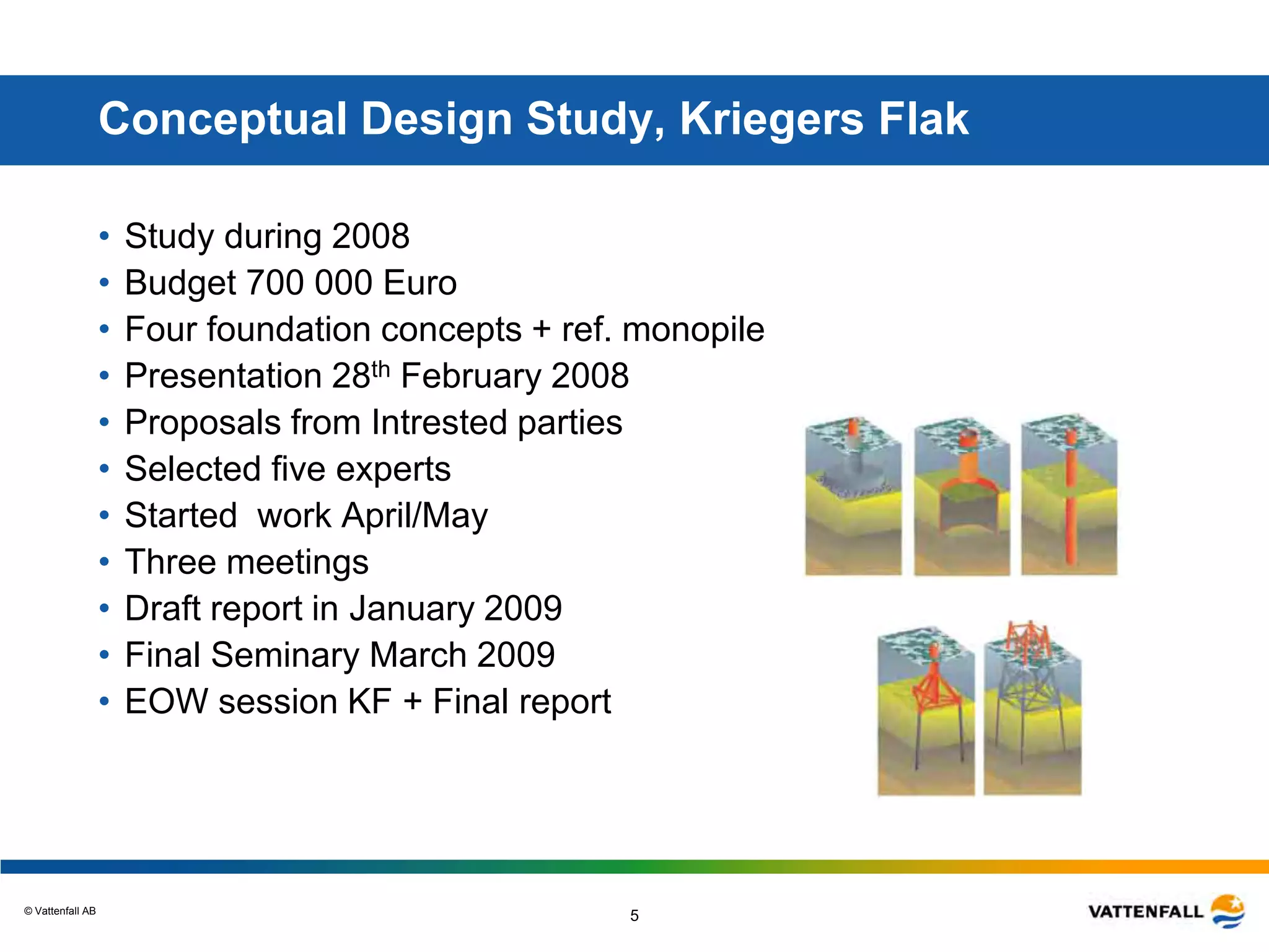
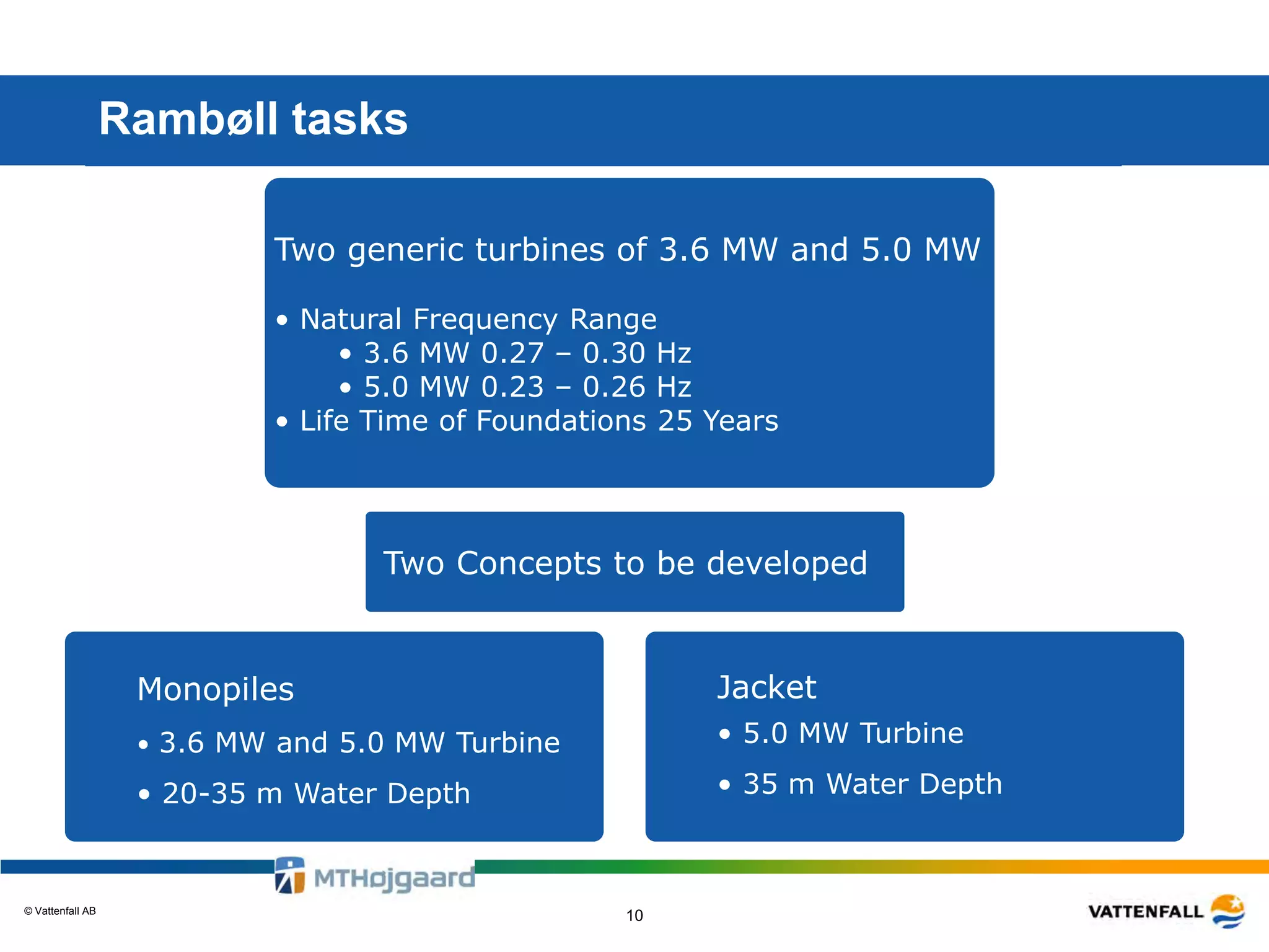
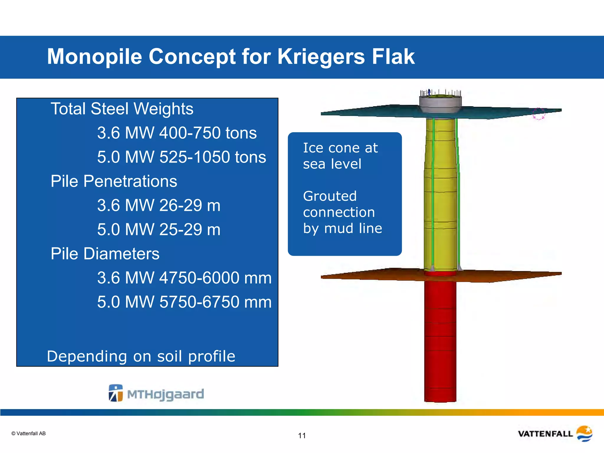
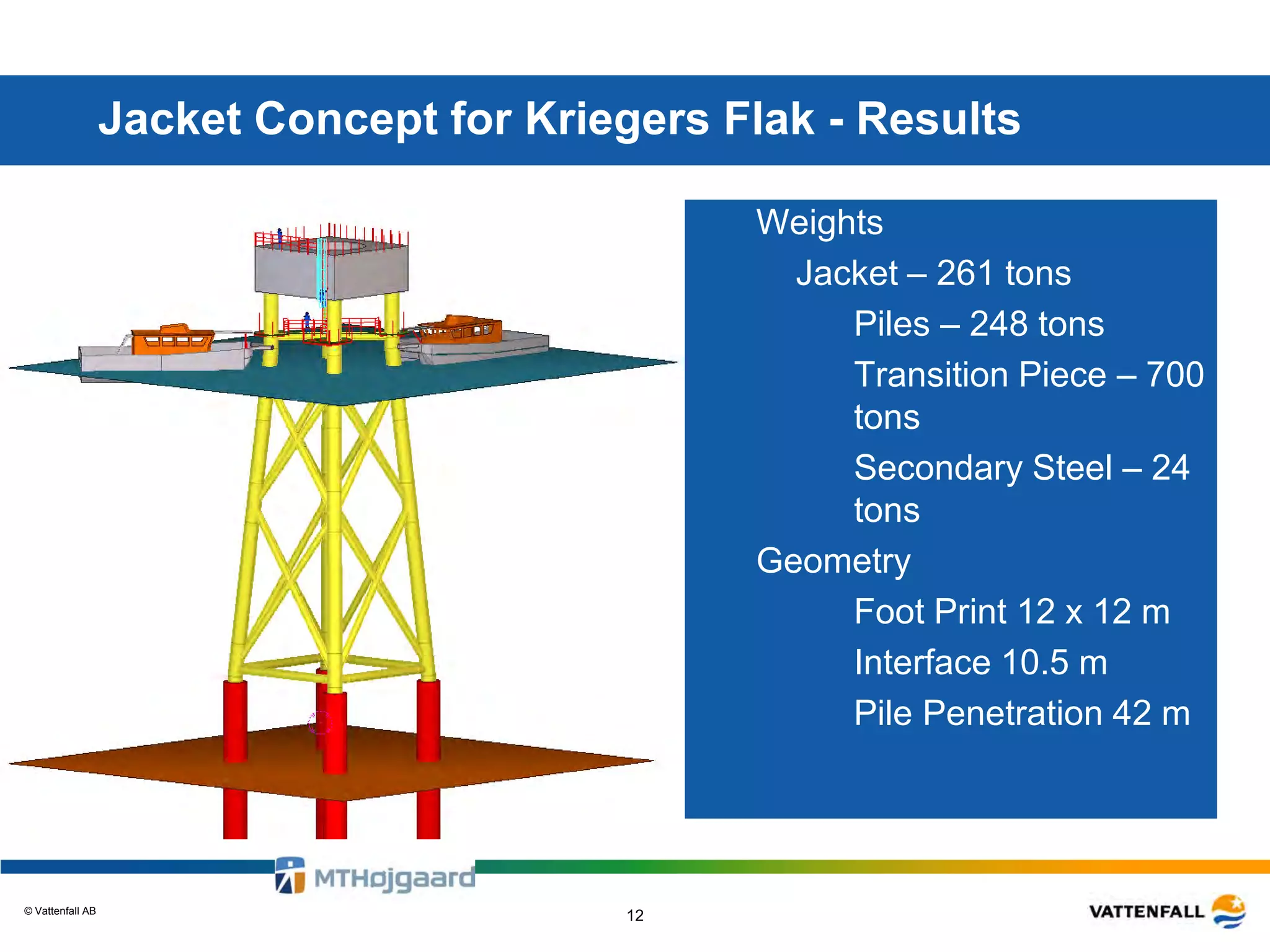
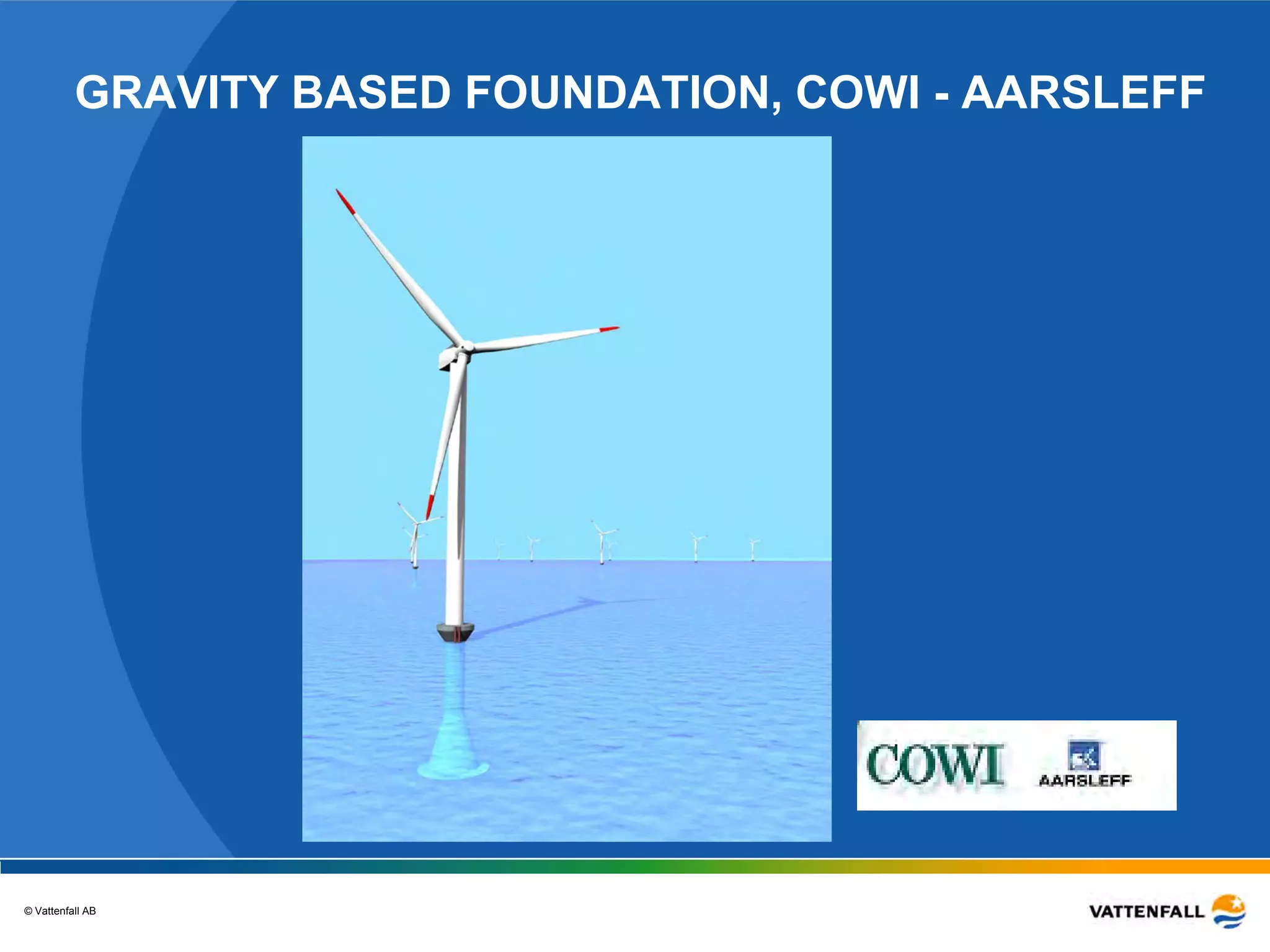
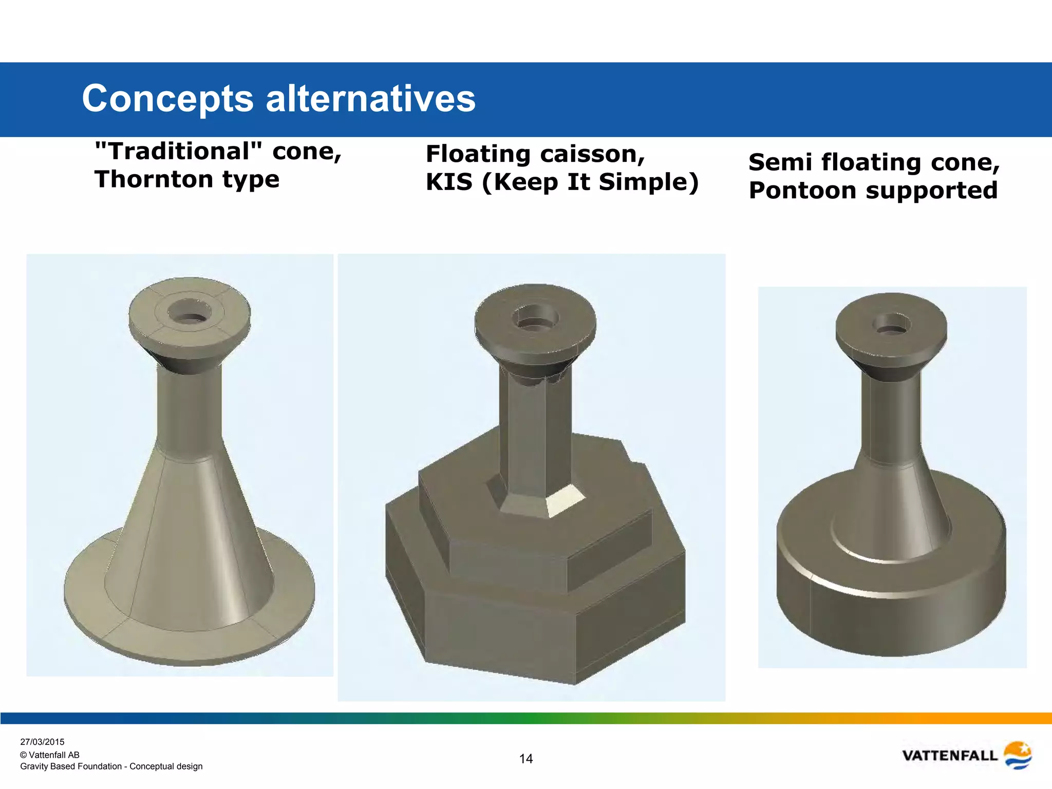
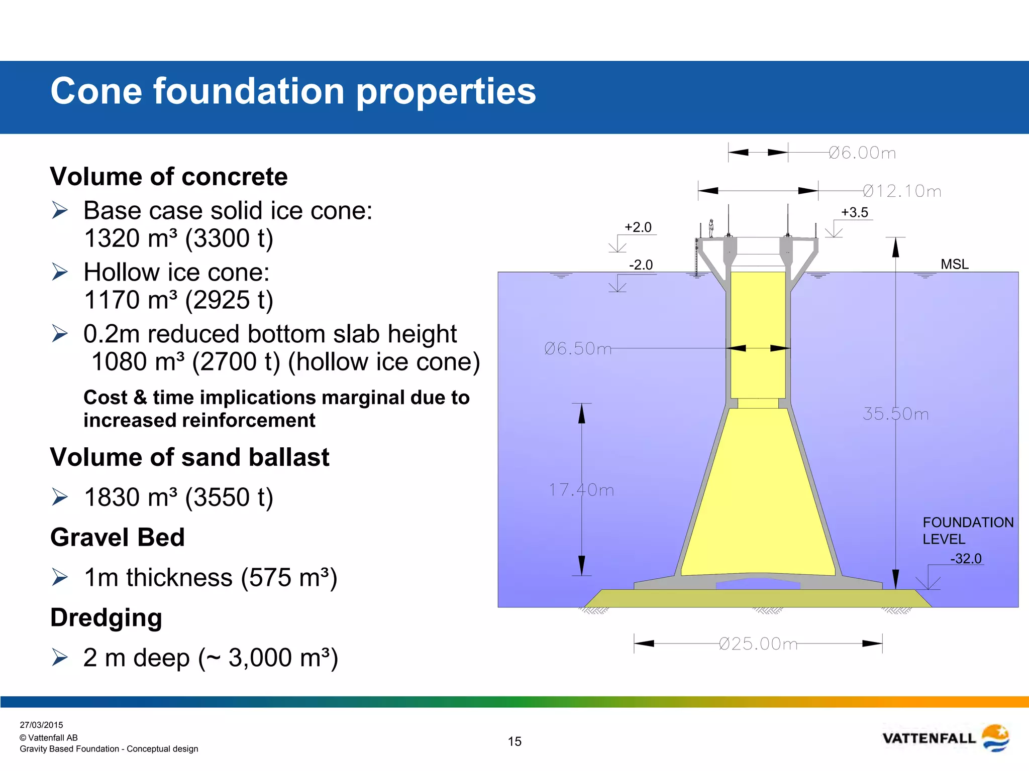
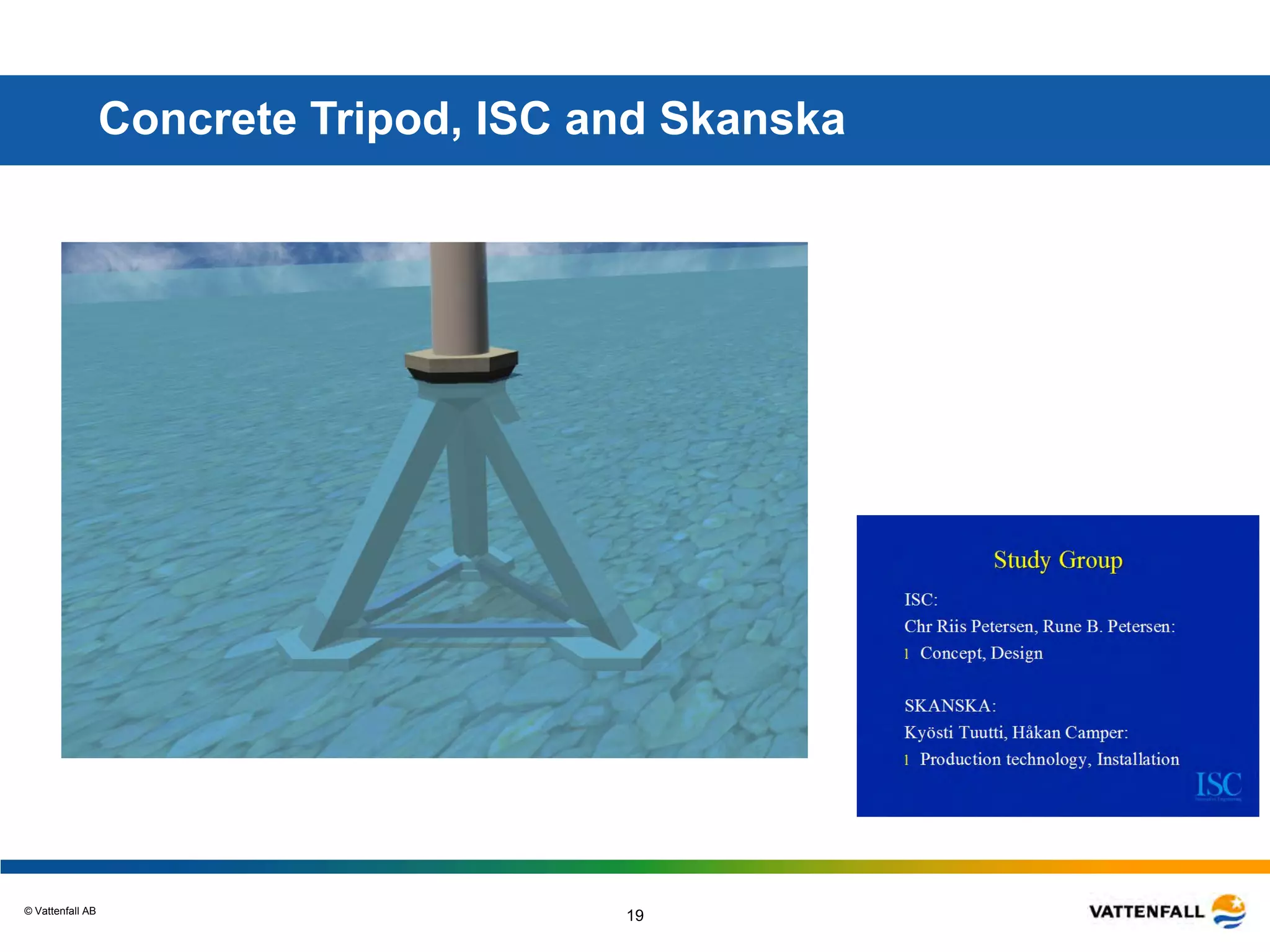
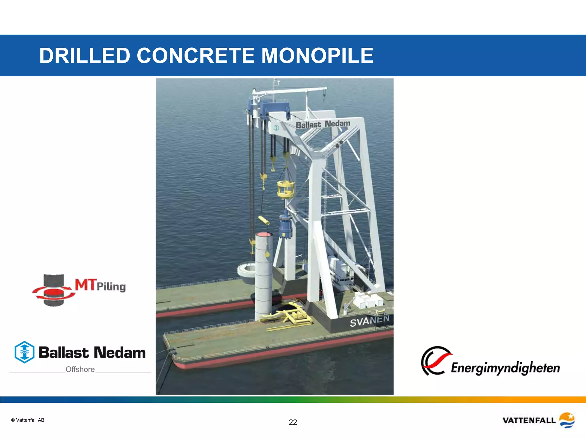
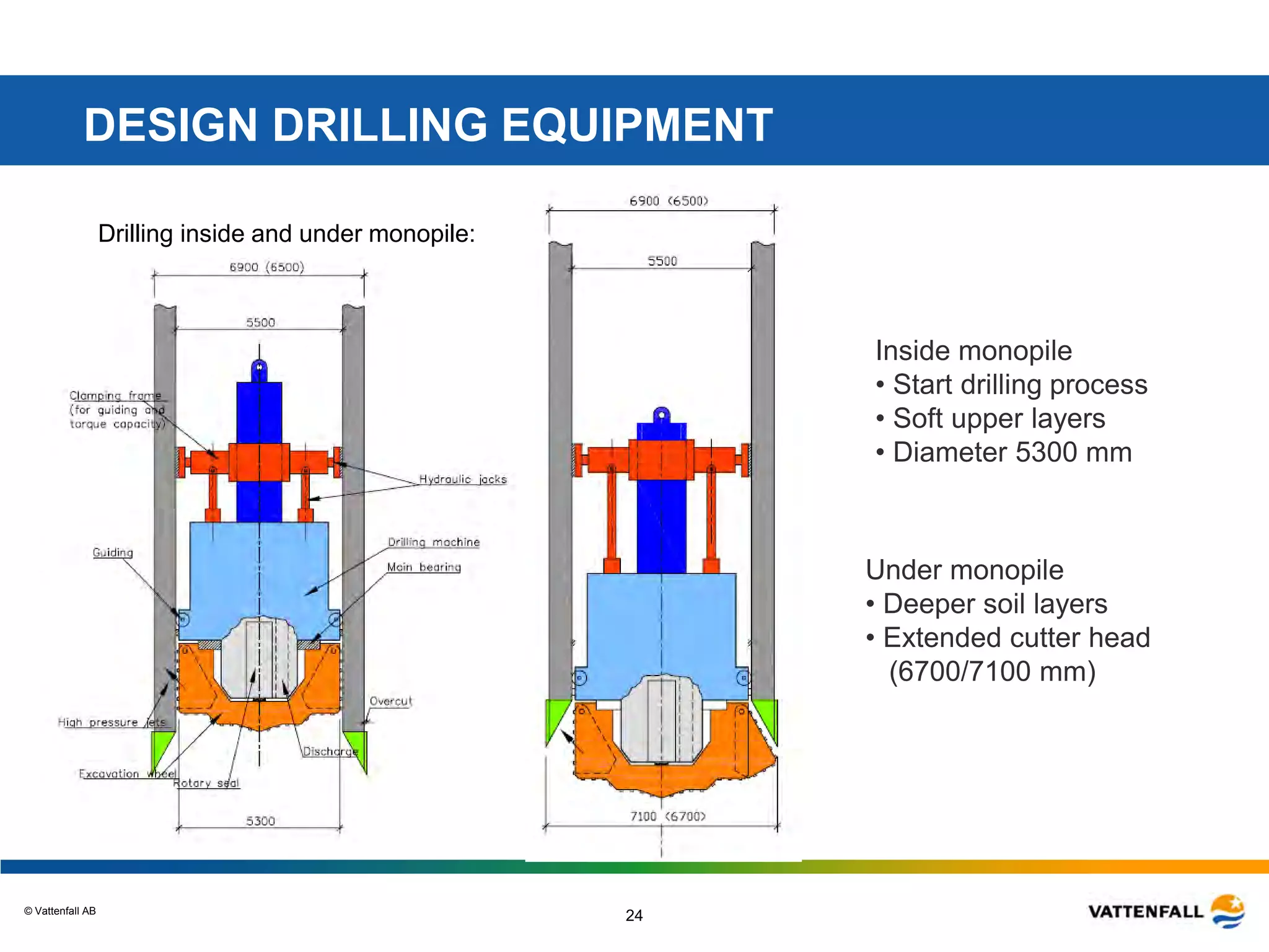
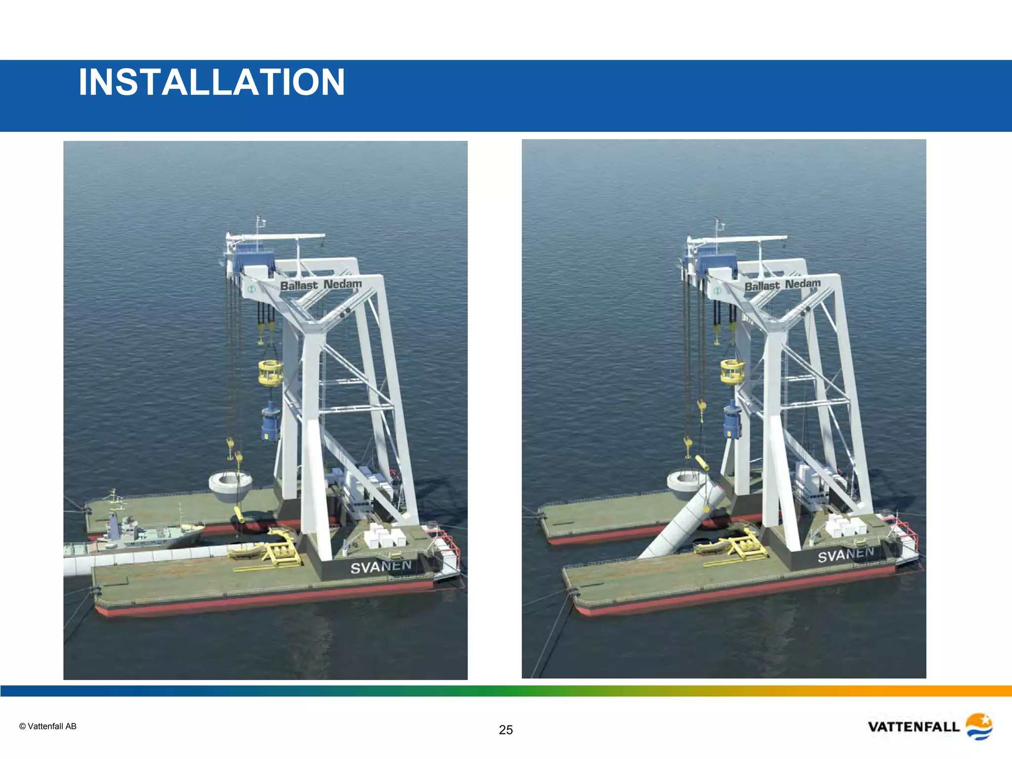
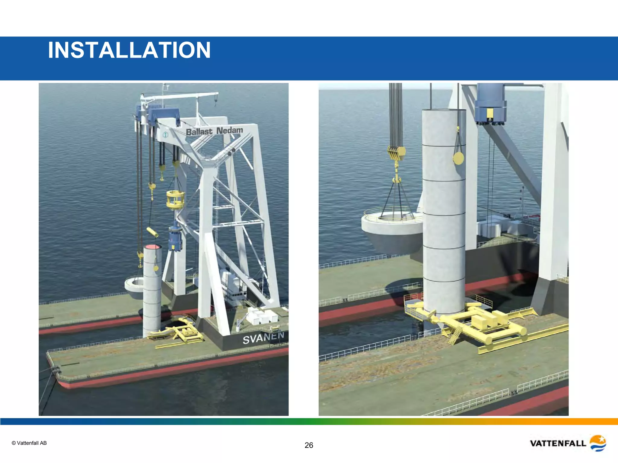
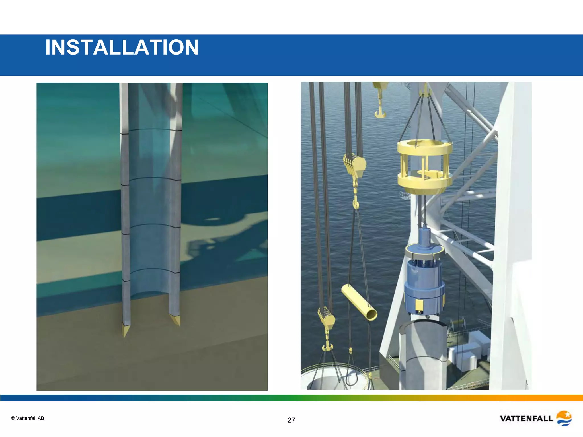
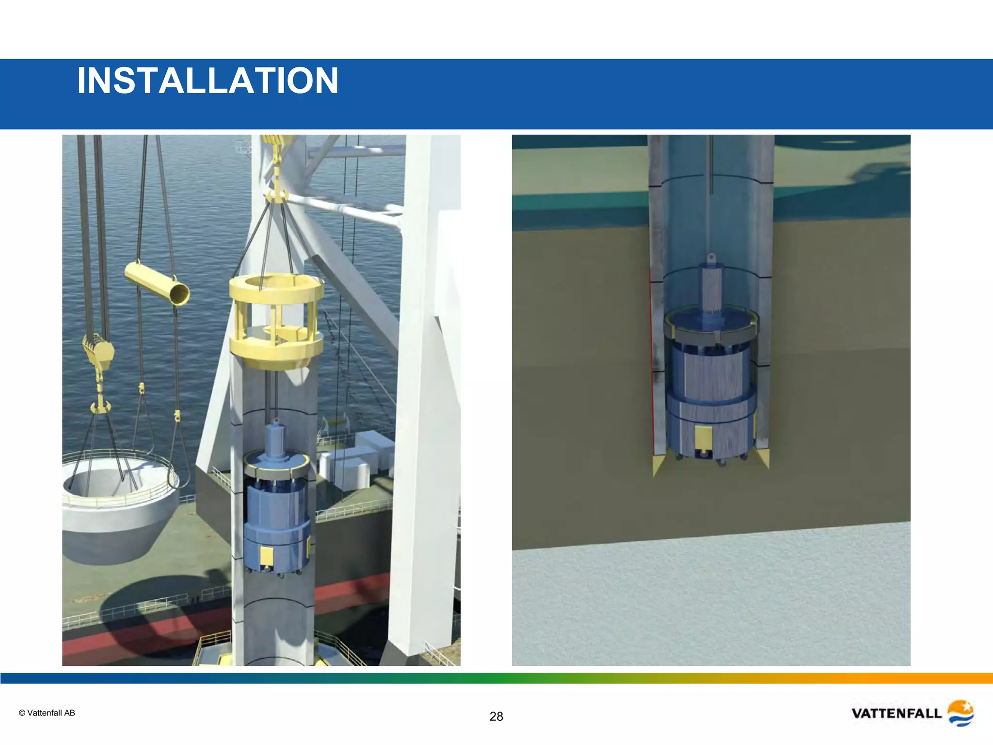
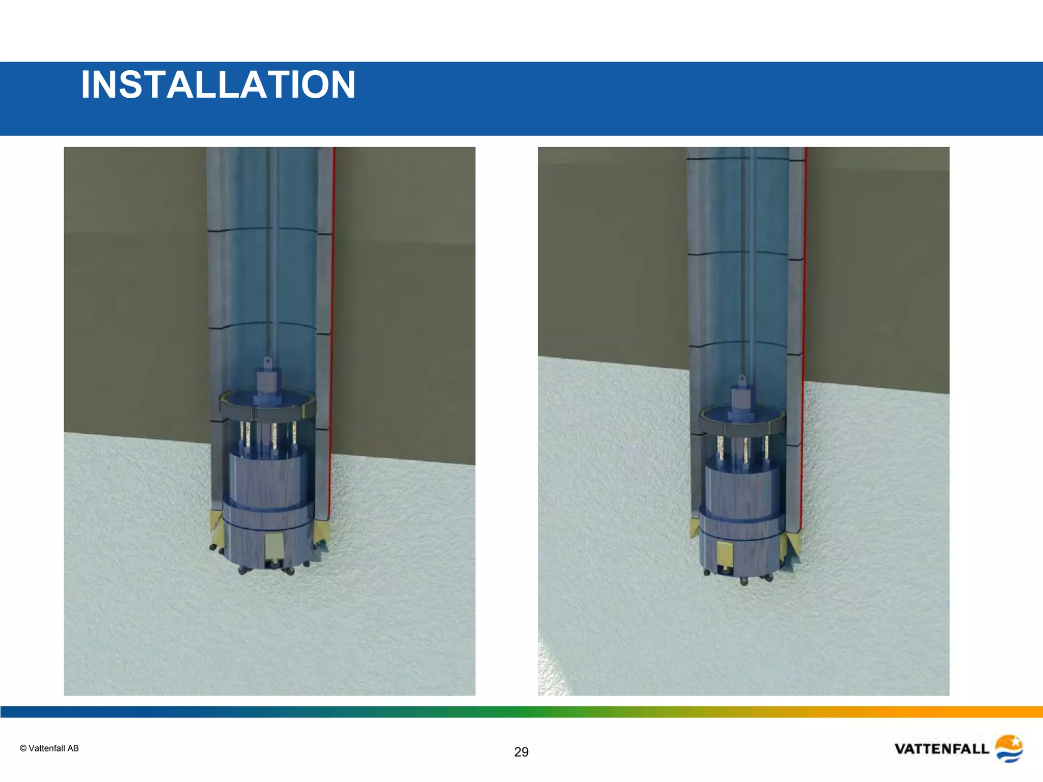
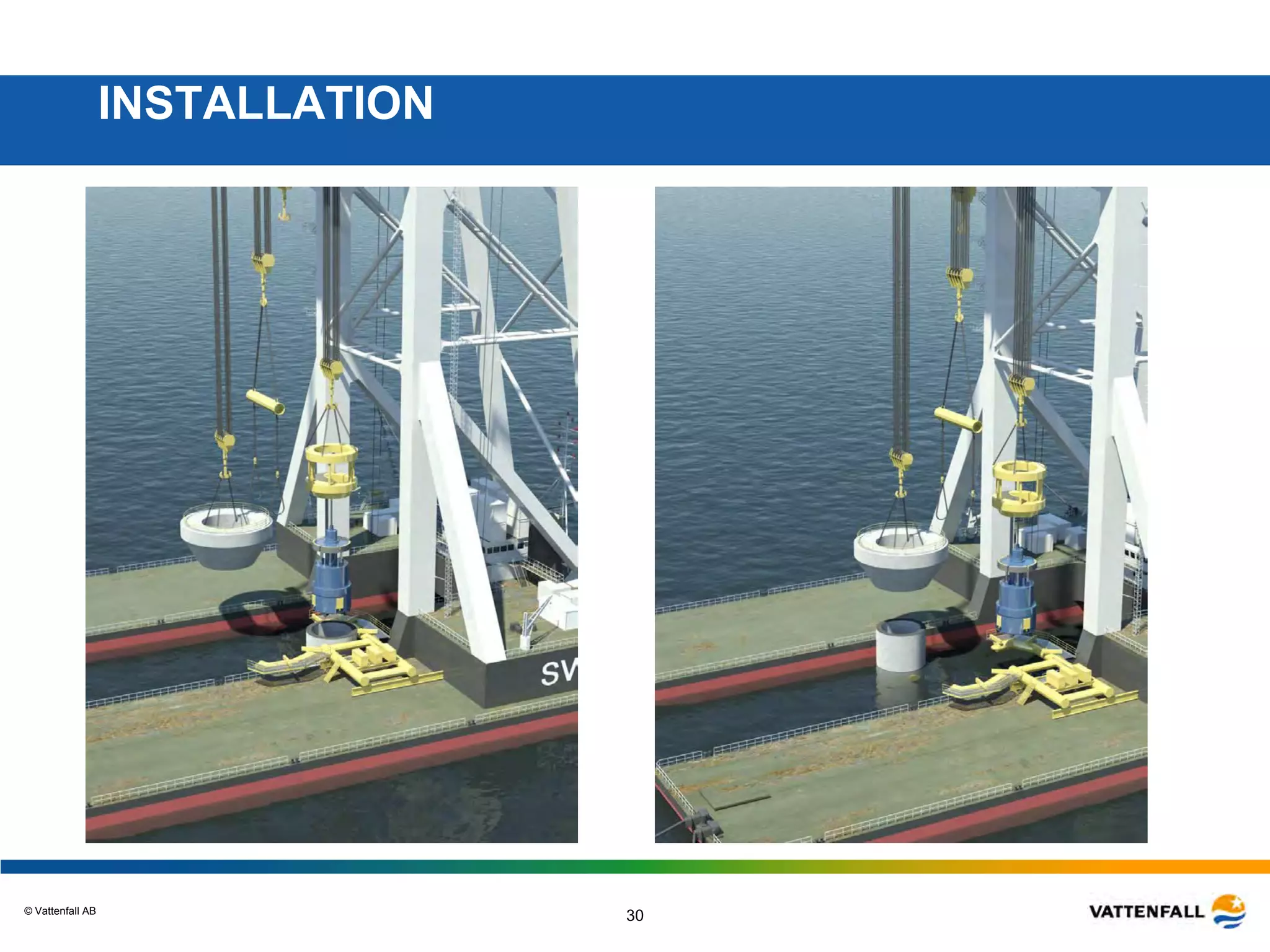
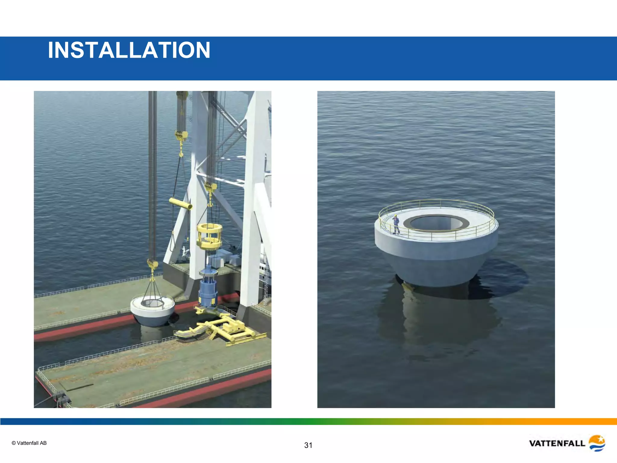
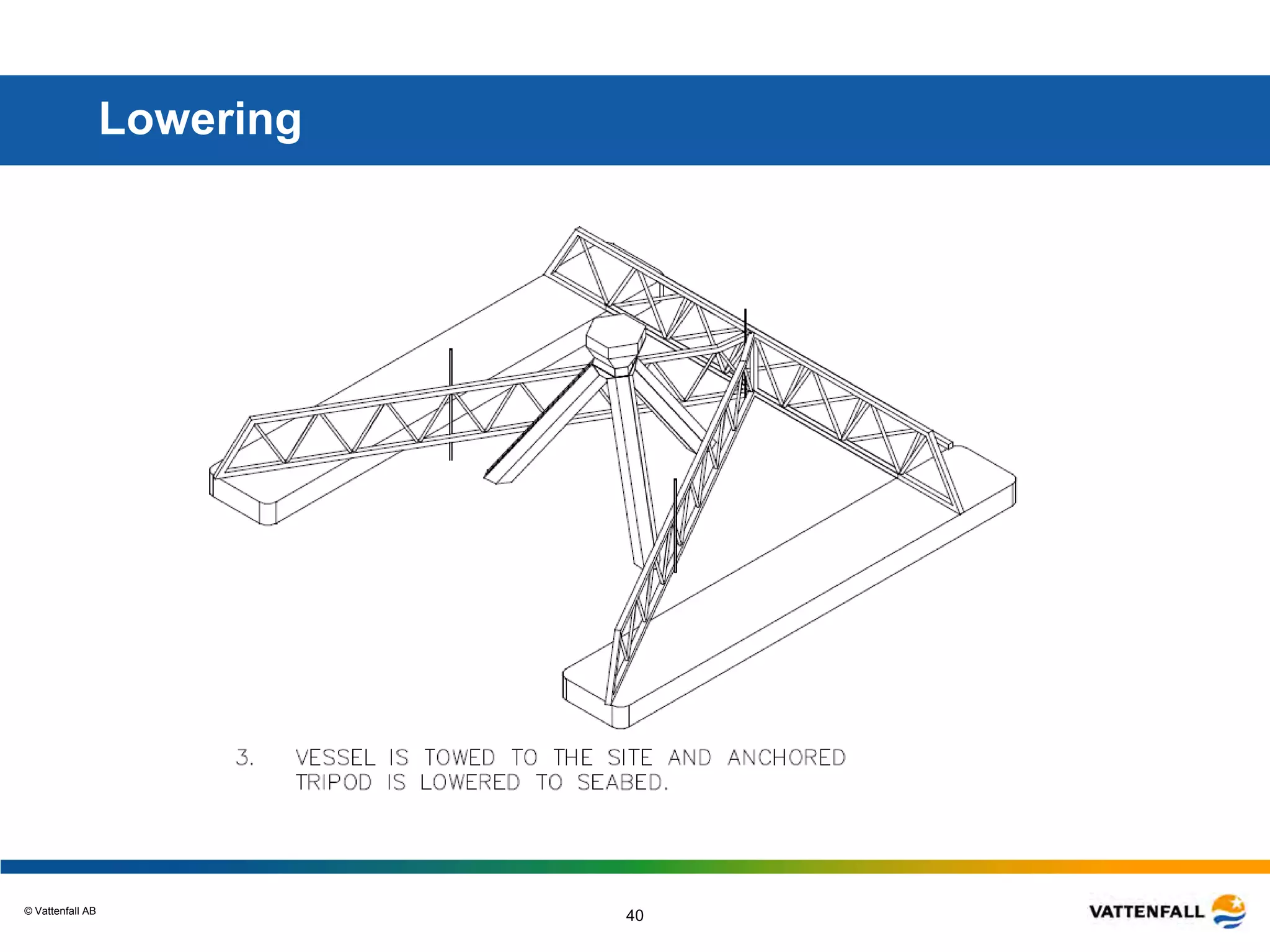
© Vattenfall AB
Conceptual Design Study
Kriegers Flak
Windforce 09, 18th june, 2009
Thomas Stalin, Vattenfall Wind Power AB
© Vattenfall AB
2
Vattenfall Wind Power
• Activity in DK, FI, SE, UK, DE, PL
• Appr. 160 employee + x consultants
• VF Target in Europe, 49 TWh wind power
by 2030
• One offshore project will be built per
year in Europe
• Thanet, UK
• Electricity to 10 million households
• 1/3 Nordic 1/3 UK 1/3 Central Europe
© Vattenfall AB
3
Targets for Sweden
• Vattenfall share 8 TWh of 16 TWh to 2016
– 4 TWh onshore
– 4 TWh offshore
• New political target 25 TWh to 2020
– Vattenfalls share even larger!!!!
• Focus in Sweden first be onshore in the forest
• Offshore has high technical risk and high investment cost
• Price for green certificates equal for onshore and offshore
• Vattenfall will first build offshore in the countries where we can
meet profitability, GB and DE
• When turbines have matured and total price for green electricity
has increased we will build offshore in Sweden
– Political process
• Kriegers flak is planned to be built in phases starting 2013
© Vattenfall AB
44
SE 103 wtg
160 MW - 440 GWh
FI 10 wtg
4 MW - 8 GWh
DE 386 wtg
307 MW - 800 GWh
UK 30 wtg
90 MW - 270 GWh
Total: Appr. 560 wtg 600 MW 1.6 TWh
Nordic: Appr. 500 wtg 470 MW 1.3 TWh
1.6 TWh Annual Production
PL 15 wtg
30 MW - 60 GWh
DE 13 wtg
14 MW - 29 GWh
© Vattenfall AB
5
Conceptual Design Study, Kriegers Flak
• Study during 2008
• Budget 700 000 Euro
• Four foundation concepts + ref. monopile
• Presentation 28th February 2008
• Proposals from Intrested parties
• Selected five experts
• Started work April/May
• Three meetings
• Draft report in January 2009
• Final Seminary March 2009
• EOW session KF + Final report
© Vattenfall AB
6
Aim of Project
• Costefficient Foundations for 15 to 45 meter water deepths
– Calculations and drawings
– Installation method and specification of equipment
– Including estimate of fabrication and installation cost
• Reduce the cost = Reduce the risk
– Use the time to investigate the conditions
– Find areas that needs further investigations
• Conceptual design for the tender process
– Good base for estimate of volumes of material and labour
– Detailed drawings and worked through concepts
• Establish contacts to Contractors well in advance of tender
– Good knowledge of the project
• Transfer of knowledge to Vattenfall
– Ability to make conceptual design and estimate cost
• Support the generall knowledge
– Develop concepts for deeper waters
© Vattenfall AB
7
Prehistory
• Year 2003 to 2005 Project development focused on permits and
not on implementations and long term ownership
– Millions on environmental investigation
– Before permit => 100% risk to loose money invested in technical
problem solving
– Long technical lead times when permit ready
=> Work in parallel
• Project development without knowing final cost
• No projects built on deep waters
• STEM Call for Offshore Pilot Studies
• Application in March April 2004
• In May 2005 project sold to Vattenfall
– Long term ownership
• Funds approved by STEM 2005
© Vattenfall AB
8
Background
• Started Design Basis 2007
• Detailed geotechnical investigation 2007
– Geobore S, CPTs, Vibro core
– Analyse first half 2008
• How to utilize time to reduce risk
– While project starts 2013
• How to get lower prices for foundations
– Better information for tendering phase
– Several pre-engineered concepts
– Contractors see possibilities and understand risk
• Optimal time schedule for tendering process
– Adopt time to allow the best solution a chance to win
• Volunteer before tendering in order to get the things done in advance
that should be done but normally first is done after the contract is signed
© Vattenfall AB
9
Consultants
• Ramböll and MTHojgaard
– Jacket
– Ref. Monopile
• ISC and Skanska
– Concrete Tripod
• COWI and Aahrsleff
– Cone Gravity foundation
• Ballast Nedam and MTPiling
– Drilled Concrete Monopile
• Pihl
– Automatic stone bed preparation robot
© Vattenfall AB
10
Rambøll tasks
Two generic turbines of 3.6 MW and 5.0 MW
• Natural Frequency Range
• 3.6 MW 0.27 – 0.30 Hz
• 5.0 MW 0.23 – 0.26 Hz
• Life Time of Foundations 25 Years
Monopiles
• 3.6 MW and 5.0 MW Turbine
• 20-35 m Water Depth
Jacket
• 5.0 MW Turbine
• 35 m Water Depth
Two Concepts to be developed
© Vattenfall AB
11
Monopile Concept for Kriegers Flak
Total Steel Weights
• 3.6 MW 400-750 tons
• 5.0 MW 525-1050 tons
Pile Penetrations
• 3.6 MW 26-29 m
• 5.0 MW 25-29 m
Pile Diameters
• 3.6 MW 4750-6000 mm
• 5.0 MW 5750-6750 mm
Ice cone at
sea level
Grouted
connection
by mud line
Depending on soil profile
© Vattenfall AB
12
Jacket Concept for Kriegers Flak - Results
Weights
– Jacket – 261 tons
• Piles – 248 tons
• Transition Piece – 700
tons
• Secondary Steel – 24
tons
Geometry
• Foot Print 12 x 12 m
• Interface 10.5 m
• Pile Penetration 42 m
© Vattenfall AB
GRAVITY BASED FOUNDATION, COWI - AARSLEFF
© Vattenfall AB
27/03/2015
Gravity Based Foundation - Conceptual design
14
Concepts alternatives
"Traditional" cone,
Thornton type
Floating caisson,
KIS (Keep It Simple)
Semi floating cone,
Pontoon supported
© Vattenfall AB
27/03/2015
Gravity Based Foundation - Conceptual design
15
Cone foundation properties
Volume of concrete
 Base case solid ice cone:
1320 m³ (3300 t)
 Hollow ice cone:
1170 m³ (2925 t)
 0.2m reduced bottom slab height
1080 m³ (2700 t) (hollow ice cone)
Cost & time implications marginal due to
increased reinforcement
Volume of sand ballast
 1830 m³ (3550 t)
Gravel Bed
 1m thickness (575 m³)
Dredging
 2 m deep (~ 3,000 m³)
-32.0
FOUNDATION
LEVEL
+2.0
-2.0
+3.5
MSL
© Vattenfall AB
16
Concept level Cost Estimate
1 Cone Foundation of 40 in total
EUR excl. VAT
Casting Yard (1 of 40) 175,000
Primary Structures: 1.125,000
Secondary Structures: 85,000
Ballast 40,000
Dredging and deposit: 135,000
Stone works: 470,000
Transport & Installation 350,000
SUM 2,380,000 ~ 480,000 EUR/MW
Assuming normal weather year,
Hs < 0.75 m 140 days Feb. - Nov.
Floating concept: ~ 4,000,000 EUR
Semi floating concept: ~ 3,000,000 EUR
© Vattenfall AB
17
Construction/installation KIS - TOWING
Transport
 Towed to installation site by
tugs
Installation
 Lowered by ballasting , tug
aided positioning
 Stability to be assured during
lowering
© Vattenfall AB
18
Construction/installation
SEMI FLOATING - Transport
Construction
 Completed on land, and immersed in shallow waters (dry dock,
skidding ramp, syncrolift)
Transport
 The GBF picked up by pontoon and transported to site
Installation
 Controlled lowering by hydraulic winches and released when in
place
© Vattenfall AB
19
Concrete Tripod, ISC and Skanska
© Vattenfall AB
20
© Vattenfall AB
21
© Vattenfall AB
22
DRILLED CONCRETE MONOPILE
© Vattenfall AB
23
FABRICATION
Fabrication method conform project
Saudi Arabia Bahrain Causeway (1984):
• Prefab reinforcement cages;
• Casting ring elements;
• Storage and curing ring elements;
• Monopile assembly:
• Aligning ements;
• Grouting element joints;
• Installation post tensioning;
• Grouting post tensioning ducts.
• Finishing works:
• Installation cutting toe;
• Installation injection lines for drillmix;
• Installation pile plugs.
© Vattenfall AB
24
Drilling inside and under monopile:
Inside monopile
• Start drilling process
• Soft upper layers
• Diameter 5300 mm
DESIGN DRILLING EQUIPMENT
Under monopile
• Deeper soil layers
• Extended cutter head
(6700/7100 mm)
© Vattenfall AB
25
INSTALLATION
© Vattenfall AB
26
INSTALLATION
© Vattenfall AB
27
INSTALLATION
© Vattenfall AB
28
INSTALLATION
© Vattenfall AB
29
INSTALLATION
© Vattenfall AB
30
INSTALLATION
© Vattenfall AB
31
INSTALLATION
© Vattenfall AB
32
COST
Total cost per MW as function of amount and turbine type:
© Vattenfall AB
33
© Vattenfall AB
34
© Vattenfall AB
35
© Vattenfall AB
36
© Vattenfall AB
37
© Vattenfall AB
38
Purpose Built Vessel
© Vattenfall AB
39
Catamaran
© Vattenfall AB
40
Lowering
© Vattenfall AB
41
Result
• Based on Geotechnical investigations and measurements on Wind and
Waves we have developed a Design Basis that was used in the project
– First test of design basis
• Individual experts developed the concepts with comments from the others
experts, team-work under competition, sharing of experience. Helge
Gravesen was the project manager
• Worked out five foundation concepts and one seabed preparation robot
• Managed to find some solutions in the range below 500 Euro/kW
• For the coming Tender process we have a good material in form of the five
worked out Conceptual designs
• Vattenfall gained knowledge on volumes, prices and time schedules
• The contractors knows about KF
– the conditions, the potential alternatives and the competition.
• Proved to be possible to create exchange between competitive parties
• Two complete new concepts have been developed
• All participants have enjoyed the process
© Vattenfall AB
Thanks!

Conceptual design study Kriegers Flak 090618 redused

  • 1.
    © Vattenfall AB ConceptualDesign Study Kriegers Flak Windforce 09, 18th june, 2009 Thomas Stalin, Vattenfall Wind Power AB
  • 2.
    © Vattenfall AB 2 VattenfallWind Power • Activity in DK, FI, SE, UK, DE, PL • Appr. 160 employee + x consultants • VF Target in Europe, 49 TWh wind power by 2030 • One offshore project will be built per year in Europe • Thanet, UK • Electricity to 10 million households • 1/3 Nordic 1/3 UK 1/3 Central Europe
  • 3.
    © Vattenfall AB 3 Targetsfor Sweden • Vattenfall share 8 TWh of 16 TWh to 2016 – 4 TWh onshore – 4 TWh offshore • New political target 25 TWh to 2020 – Vattenfalls share even larger!!!! • Focus in Sweden first be onshore in the forest • Offshore has high technical risk and high investment cost • Price for green certificates equal for onshore and offshore • Vattenfall will first build offshore in the countries where we can meet profitability, GB and DE • When turbines have matured and total price for green electricity has increased we will build offshore in Sweden – Political process • Kriegers flak is planned to be built in phases starting 2013
  • 4.
    © Vattenfall AB 44 SE103 wtg 160 MW - 440 GWh FI 10 wtg 4 MW - 8 GWh DE 386 wtg 307 MW - 800 GWh UK 30 wtg 90 MW - 270 GWh Total: Appr. 560 wtg 600 MW 1.6 TWh Nordic: Appr. 500 wtg 470 MW 1.3 TWh 1.6 TWh Annual Production PL 15 wtg 30 MW - 60 GWh DE 13 wtg 14 MW - 29 GWh
  • 5.
    © Vattenfall AB 5 ConceptualDesign Study, Kriegers Flak • Study during 2008 • Budget 700 000 Euro • Four foundation concepts + ref. monopile • Presentation 28th February 2008 • Proposals from Intrested parties • Selected five experts • Started work April/May • Three meetings • Draft report in January 2009 • Final Seminary March 2009 • EOW session KF + Final report
  • 6.
    © Vattenfall AB 6 Aimof Project • Costefficient Foundations for 15 to 45 meter water deepths – Calculations and drawings – Installation method and specification of equipment – Including estimate of fabrication and installation cost • Reduce the cost = Reduce the risk – Use the time to investigate the conditions – Find areas that needs further investigations • Conceptual design for the tender process – Good base for estimate of volumes of material and labour – Detailed drawings and worked through concepts • Establish contacts to Contractors well in advance of tender – Good knowledge of the project • Transfer of knowledge to Vattenfall – Ability to make conceptual design and estimate cost • Support the generall knowledge – Develop concepts for deeper waters
  • 7.
    © Vattenfall AB 7 Prehistory •Year 2003 to 2005 Project development focused on permits and not on implementations and long term ownership – Millions on environmental investigation – Before permit => 100% risk to loose money invested in technical problem solving – Long technical lead times when permit ready => Work in parallel • Project development without knowing final cost • No projects built on deep waters • STEM Call for Offshore Pilot Studies • Application in March April 2004 • In May 2005 project sold to Vattenfall – Long term ownership • Funds approved by STEM 2005
  • 8.
    © Vattenfall AB 8 Background •Started Design Basis 2007 • Detailed geotechnical investigation 2007 – Geobore S, CPTs, Vibro core – Analyse first half 2008 • How to utilize time to reduce risk – While project starts 2013 • How to get lower prices for foundations – Better information for tendering phase – Several pre-engineered concepts – Contractors see possibilities and understand risk • Optimal time schedule for tendering process – Adopt time to allow the best solution a chance to win • Volunteer before tendering in order to get the things done in advance that should be done but normally first is done after the contract is signed
  • 9.
    © Vattenfall AB 9 Consultants •Ramböll and MTHojgaard – Jacket – Ref. Monopile • ISC and Skanska – Concrete Tripod • COWI and Aahrsleff – Cone Gravity foundation • Ballast Nedam and MTPiling – Drilled Concrete Monopile • Pihl – Automatic stone bed preparation robot
  • 10.
    © Vattenfall AB 10 Rambølltasks Two generic turbines of 3.6 MW and 5.0 MW • Natural Frequency Range • 3.6 MW 0.27 – 0.30 Hz • 5.0 MW 0.23 – 0.26 Hz • Life Time of Foundations 25 Years Monopiles • 3.6 MW and 5.0 MW Turbine • 20-35 m Water Depth Jacket • 5.0 MW Turbine • 35 m Water Depth Two Concepts to be developed
  • 11.
    © Vattenfall AB 11 MonopileConcept for Kriegers Flak Total Steel Weights • 3.6 MW 400-750 tons • 5.0 MW 525-1050 tons Pile Penetrations • 3.6 MW 26-29 m • 5.0 MW 25-29 m Pile Diameters • 3.6 MW 4750-6000 mm • 5.0 MW 5750-6750 mm Ice cone at sea level Grouted connection by mud line Depending on soil profile
  • 12.
    © Vattenfall AB 12 JacketConcept for Kriegers Flak - Results Weights – Jacket – 261 tons • Piles – 248 tons • Transition Piece – 700 tons • Secondary Steel – 24 tons Geometry • Foot Print 12 x 12 m • Interface 10.5 m • Pile Penetration 42 m
  • 13.
    © Vattenfall AB GRAVITYBASED FOUNDATION, COWI - AARSLEFF
  • 14.
    © Vattenfall AB 27/03/2015 GravityBased Foundation - Conceptual design 14 Concepts alternatives "Traditional" cone, Thornton type Floating caisson, KIS (Keep It Simple) Semi floating cone, Pontoon supported
  • 15.
    © Vattenfall AB 27/03/2015 GravityBased Foundation - Conceptual design 15 Cone foundation properties Volume of concrete  Base case solid ice cone: 1320 m³ (3300 t)  Hollow ice cone: 1170 m³ (2925 t)  0.2m reduced bottom slab height 1080 m³ (2700 t) (hollow ice cone) Cost & time implications marginal due to increased reinforcement Volume of sand ballast  1830 m³ (3550 t) Gravel Bed  1m thickness (575 m³) Dredging  2 m deep (~ 3,000 m³) -32.0 FOUNDATION LEVEL +2.0 -2.0 +3.5 MSL
  • 16.
    © Vattenfall AB 16 Conceptlevel Cost Estimate 1 Cone Foundation of 40 in total EUR excl. VAT Casting Yard (1 of 40) 175,000 Primary Structures: 1.125,000 Secondary Structures: 85,000 Ballast 40,000 Dredging and deposit: 135,000 Stone works: 470,000 Transport & Installation 350,000 SUM 2,380,000 ~ 480,000 EUR/MW Assuming normal weather year, Hs < 0.75 m 140 days Feb. - Nov. Floating concept: ~ 4,000,000 EUR Semi floating concept: ~ 3,000,000 EUR
  • 17.
    © Vattenfall AB 17 Construction/installationKIS - TOWING Transport  Towed to installation site by tugs Installation  Lowered by ballasting , tug aided positioning  Stability to be assured during lowering
  • 18.
    © Vattenfall AB 18 Construction/installation SEMIFLOATING - Transport Construction  Completed on land, and immersed in shallow waters (dry dock, skidding ramp, syncrolift) Transport  The GBF picked up by pontoon and transported to site Installation  Controlled lowering by hydraulic winches and released when in place
  • 19.
    © Vattenfall AB 19 ConcreteTripod, ISC and Skanska
  • 20.
  • 21.
  • 22.
    © Vattenfall AB 22 DRILLEDCONCRETE MONOPILE
  • 23.
    © Vattenfall AB 23 FABRICATION Fabricationmethod conform project Saudi Arabia Bahrain Causeway (1984): • Prefab reinforcement cages; • Casting ring elements; • Storage and curing ring elements; • Monopile assembly: • Aligning ements; • Grouting element joints; • Installation post tensioning; • Grouting post tensioning ducts. • Finishing works: • Installation cutting toe; • Installation injection lines for drillmix; • Installation pile plugs.
  • 24.
    © Vattenfall AB 24 Drillinginside and under monopile: Inside monopile • Start drilling process • Soft upper layers • Diameter 5300 mm DESIGN DRILLING EQUIPMENT Under monopile • Deeper soil layers • Extended cutter head (6700/7100 mm)
  • 25.
  • 26.
  • 27.
  • 28.
  • 29.
  • 30.
  • 31.
  • 32.
    © Vattenfall AB 32 COST Totalcost per MW as function of amount and turbine type:
  • 33.
  • 34.
  • 35.
  • 36.
  • 37.
  • 38.
  • 39.
  • 40.
  • 41.
    © Vattenfall AB 41 Result •Based on Geotechnical investigations and measurements on Wind and Waves we have developed a Design Basis that was used in the project – First test of design basis • Individual experts developed the concepts with comments from the others experts, team-work under competition, sharing of experience. Helge Gravesen was the project manager • Worked out five foundation concepts and one seabed preparation robot • Managed to find some solutions in the range below 500 Euro/kW • For the coming Tender process we have a good material in form of the five worked out Conceptual designs • Vattenfall gained knowledge on volumes, prices and time schedules • The contractors knows about KF – the conditions, the potential alternatives and the competition. • Proved to be possible to create exchange between competitive parties • Two complete new concepts have been developed • All participants have enjoyed the process
  • 42.