SlideShare a Scribd company logo
1 of 353
Download to read offline
COMPUTER NETWORKS
(A50515)
Prepared By:
Mr. N Bhaswanth
IARE10038
Assistant Professor
Information Technology
UNIT-I
Overview of the Internet: Protocol, Layering Scenario, TCP/IP Protocol Suite: The
OSI Model, Internet history standards and administration.Comparision of the OSI and
TCP/IP reference model.
Physical Layer: Guided transmission media, wireless transmission media.
Data Link Layer-design issues, CRC Codes, Elementary Data link Layer protocols,
sliding window protocol.
PROTOCOLS AND STANDARDS
Protocol
A protocol is a set of rules that govern data communications. A protocol defines what is
communicated, how it is communicated, and when it is communicated. The key elements
of a protocol are syntax, semantics, and timing
Syntax
The term syntax refers to the structure or format of the data, meaning the order in which
they are presented
For example, a simple protocol might expect the first 8 bits of data to be the address of the
sender, the second 8 bits to be the address of the receiver, and the rest of the stream to be
the message itself.
Semantics
The word semantics refers to the meaning of each section of bits.
For example, does an address identify the route to be taken or the final destination
of the message?
Timing
The term timing refers to two characteristics: when data should be sent and how fast
they can be sent.
For example, if a sender produces data at 100 Mbps but the receiver can process data
at only 1 Mbps, the transmission will overload the receiver and some data will be lost.
Interfaces Between Layers
The passing of the data and network information down through the layers of the sending
device and back up through the layers of the receiving device is made possible by an
interface between each pair of adjacent layers.
Each interface defines the information and services a layer must provide for the layer
above it. Well-defined interfaces and layer functions provide modularity to a network.
As long as a layer provides the expected services to the layer above it, the specific
implementation of its functions can be modified or replaced without requiring changes to
the surrounding layers
2.4
An exchange using the OSImodel
LAYERS IN THE OSI MODEL
1. Physicallayer
The physical layer is responsible for movements of
individual bits from one hop (node) to the next.
The physical layer coordinates the functions required to carry a bit stream over a
physical medium. It deals with the mechanical and electrical specifications of the
interface and transmission medium.
It also defines the procedures and functions that physical devices and interfaces
have to perform for transmission to Occur
The physical layer is also concerned with the following:
•Physical characteristics of interfaces and medium
The physical layer defines the characteristics of the interface between the devices andthe
transmission medium. It also defines the type of transmission medium.
Physicallayer
Physical topology
The physical topology defines how devices are connected to make a network.
Devices can be connected by using a mesh topology, star topology, bus topology, ring
topology or hybrid topology
Transmission mode
Physical layer defines direction of transmission between to systems
Simplex mode : only one device can send and other can only receive. It is one way
communication.
Half duplex mode: Two devices can send and receive but not at the same time
Full duplex mode: Two devices can send and receive at the same time
2.8
2. Data link layer
The data link layer is responsible for moving
frames from one hop (node) to the next.
Access control
When two or more devices are connected to the same link, data link layer protocols
are necessary to determine which device has control over the link at any given time.
The network layer is responsible for the
delivery of individual packets from
the source host to the destination host.
3.Networklayer
Network Layer
The network layer is responsible for the source-to-destination delivery of a packet, possibly
across multiple networks (links).
Whereas the data link layer oversees the delivery of the packet between two systems on the
same network (links), the network layer ensures that each packet gets from its point of origin
to its final destination.
If the two systems are attached to different networks (links) with connecting devices
between the networks (links), there is often a need for the network layer toaccomplish
source-to-destination delivery
Other responsibilities of the network layer include the following:
Logical addressing.
The physical addressing implemented by the data link layer handles theaddressing
problem locally.
If a packet passes the network boundary, we need another addressing system to help
distinguish the source and destination systems.
The network layer adds a header to the packet coming from the upper layerthat,
among other things, includes the logical addresses of the sender and receiver.
Routing
When independent networks or links are connected to create internetworks(network of
networks) or a large network, the connecting devices (called routers or switches) route
or switch the packets to their final destination. One of the functions of the network layer
is to provide this mechanism
2.13
4 .Transportlayer
The transport layer is responsible for the delivery
of a message from one process to another.
Transport Layer
A process is an application program running on ahost
The transport layer, on the other hand, ensures that the whole message arrives intact and
in order, overseeing both error control and flow control at the source-to-destination level.
Other responsibilities of the transport layer include the following:
Service-point addressing
Computers often run several programs at the same time. For this reason, source to destination
delivery means delivery not only from one computer to the next but also from a specific process
(running program) on one computer to a specific process (running program) on the other
The transport layer header must therefore include a type of address called a service-point address
(or port address).
The network layer gets each packet to the correct computer; the transport layer getsthe
entire message to the correct process on that computer.
Segmentation and reassembly
A message is divided into transmittable segments, with each segment containing a sequence
number
These numbers enable the transport layer to reassemble the message correctly upon arriving at
the destination and to identify and replace packets that were lost in transmission
Connection control
The transport layer can be either connectionless or connection oriented.
A connectionless transport layer treats each segment as an independent packet and deliversit
to the transport layer at the destination machine.
A connection oriented transport layer makes a connection with the transport layer atthe
destination machine first before delivering the packets. After all the data aretransferred
,the connection is terminated.
Flow control
Like the data link layer, the transport layer is responsible for flow control. However, flow
control at this layer is performed end to end rather than across a single link.
Errorcontrol
Like the data link layer, the transport layer is responsible for error control. However, error
control at this layer is performed process-to process rather than across a single link.
The sending transport layer makes sure that the entire message arrives at the receiving
transport layer without error(damage, loss, or duplication). Error correction is usually
achieved through retransmission.
2.17
5.Sessionlayer
The session layer is responsible for dialog
control and synchronization.
2.18
6.Presentationlayer
The presentation layer is responsible for translation,
compression, and encryption.
Presentation Layer
The presentation layer is concerned with the syntax and semantics of theinformation
exchanged between two systems.
Specific responsibilities of the presentation layer include thefollowing:
Translation
Th.eprocesses (running programs) in two systems are usually exchanging information in the
form of character strings, numbers, and so on. The information must be changed to bit
streams before being transmitted.
Because different computers use different encoding systems, the presentation layer is
responsible for interoperability between these different encoding methods.
The presentation layer at the sender changes the information from its sender-dependent
format into a common format.
The presentation layer at the receiving machine changes the common format into its
receiver-dependent format
Encryption
To carry sensitive information, a system must be able to ensure privacy.
Encryption means that the sender transforms the original information to another form and
sends the resulting message out over the network
Decryption reverses the original process to transform the message back to its original form
Compression.
Data compression reduces the number of bits contained in the information.
Data compression becomes particularly important in the transmission of multimedia such as
text, audio, and video
7.Applicationlayer
The application layer is responsible for
providing services to the user.
Application Layer
The application layer enables the user, whether human or software, to access the network.
It provides user interfaces and support for services such as electronic mail, remote file access
and transfer, shared database management, and other types of distributed information services.
Figure 2.14 shows the relationship of the application layer to the user and the presentationlayer.
Of the many application services available, the figure shows only three: XAOO (message
handling services), X.500 (directory services), and file transfer, access, and management
(FTAM). The user in this example employs XAOO to send an e-mail message
Specific services provided by the application layer include thefollowing
Network virtual terminal
A network virtual terminal is a software version of a physical terminal, and it allows auser
to log on to a remote host.
To do so, the application creates a software emulation of a terminal at the remote host.
The user's computer talks to the software terminal which, in turn, talks to the host,
and vice versa.
The remote host believes it is communicating with one of its own terminals and allows
the user to log on.
File transfer, access, and management
This application allows a user to access files in a remote host (to make changes or read data),
to retrieve files from a remote computer for use in the local computer, and to manage or control
files in a remote computer locally.
Mail services
This application provides the basis for e-mail forwarding and storage.
Directory services
This application provides distributed database sources and access for global information
about various objects and services.
TCP/IP model
TCP/IP PROTOCOLSUITE
The original TCP/IP protocol suite was defined as having fourlayers:
1 Host-to-Network Layer
2 Internet Layer
3 Transport Layer
4 Application Layer
TCPIIP protocol suite is made of five layers:
physical, data link, network, transport, and application.
The first four layers provide physical standards, network interfaces, internetworking, and
transport functions that correspond to the first four layers of the OSI model.
Transport Layer
Traditionally the transport layer was represented in TCP/IP by two protocols: TCP and UDP
IP is a host-to-host protocol, meaning that it can deliver a packet from one physical deviceto
another.
UDP and TCP are transport level protocols responsible for delivery of a message froma
process (running program) to another process.
A new transport layer protocol, SCTP, has been devised to meet the needs of some
newer applications.
User Datagram Protocol(UDP)
The User Datagram Protocol (UDP) is the simpler of the two standard TCP/IPtransport
protocols.
It is a process-to-process protocol that adds only port addresses, checksum error
control, and length information to the data from the upper layer
Transmission Control Protocol(TCP)
The Transmission Control Protocol (TCP) provides full transport-layer services to applications
TCP is a reliable stream transport protocol. A connection must be established between both
ends of a transmission before either can transmit data.
At the sending end of each transmission, TCP divides a stream of data into smaller
units called segments. Each segment includes a sequence number for reordering after
receipt, together with an acknowledgment number for the segments received.
Segments are carried across the internet inside of IP datagrams. At the receiving end,TCP
collects each datagram as it comes in and reorders the transmission based on sequence
numbers.
THE INTERNET
A BriefHistory
•A network is a group of connected communicating devices such as computers and
printers.
•In the mid-1960s, mainframe computers in research organizations were standalone devices.
•The Advanced Research Projects Agency (ARPA) in the Department of Defense
(DoD) was interested in finding a way to connect computers so that the researchers they
funded could share their findings, thereby reducing costs and eliminating duplication of
effort
•In 1967, at an Association for Computing Machinery (ACM) meeting, ARPApresented
its ideas for ARPANET, a small network of connected computers.
•In 1972, Vint Cerf and Bob Kahn, both of whom were part of the core ARPANETgroup,
collaborated on what they called the Internetting Project. Cerf and Kahn's landmark1973
paper outlined the protocols to achieve end-to-end delivery of packets. This paper on
Transmission Control Protocol (TCP) included concepts such as encapsulation, the
datagram, and the functions of a gateway.
•Shortly thereafter, authorities made a decision to split TCP into two protocols:
Transmission Control Protocol (TCP) and Internetworking Protocol (lP).. The
internetworking protocol became known as TCP/IP
The Internet Today
The Internet has come a long way since the 1960s. The Internet today is not a simple
hierarchical structure. It is made up of many wide- and local-area networks joined by
connecting devices and switching stations.
Today most end users who want Internet connection use the services of
Internet service providers (lSPs).
There are
•international service providers,
•national service providers,
•regional service providers
•local service providers.
.
CoaxialCable
Coaxial Cable
coax has a central core conductor of solid or stranded wire (usually copper) enclosed
in an insulating sheath,
The outer metallic wrapping serves both as a shield against noise and as the second
conductor, which completes the circuit.
This outer conductor is also enclosed in an insulating sheath, and the whole cable
is protected by a plasticcover
Categories of Coaxial Cables
RG – Radio Government
Applications
• Coaxial cable was widely used in analog telephone networks
• In the traditional cable TV network,the entire network used coaxial
cable
• Another common application of coaxial cable is in traditional Ethernet LANs
Fiber optics: Bending of light ray
Fiber-Optic Cable
• A fiber-optic cable is made of glass or plastic andtransmits signals in the form
of light
• Light travels in a straight line as long as it is moving througha
single uniform substance
• if the angle of incidence I is less than the critical angle, theray
refracts and moves closer to the surface
• If the angle of incidence is equal to the critical angle, thelight
bends along the interface
• If the angle is greater than the critical angle, the ray reflects and travels again in
the densersubstance.
Optical fiber
Optical fiber
• Optical fibers use reflection to guide light through achannel
• .A glass or plastic core is surrounded by a cladding of less dense glass or plastic.
• The difference in density of the two materials must be such that
• a beam of light moving through the core is reflected off the
cladding instead of being refracted into it
Modes
Multimode
• Multimode is so named because multiple beams from a light source move
through the core in different paths
• In multimode step-index fiber, the density of the core
remains constant from the center to the edges.
• A beam of light moves through this constant density in a straight line until it
reaches the interface of the core andthe cladding
• step index refers to the suddenness of this change, which contributes to the
distortion of the signal as it passes through the fiber.
Multimode
• multimode graded-index fiber, decreases this distortion of the signal through
the cable
• A graded-index fiber, therefore, is one with varying densities. Density is highest
at the center of the core and decreases gradually to its lowest at the edge.
Single-Mode
• Single-mode uses step-index fiber and a highly focused source of light
• that limits beams to a small range of angles, all close to the horizontal
• propagation of different beams is almost identical, and delays are negligible.
• All the beams arrive at the destination "together" and
can be recombined with little distortion to the signal
Applications
• Fiber-optic cable is often found in backbone networks
• cable TV companies use a combination of optical fiberand coaxial cable, thus
creating a hybridnetwork
• Local-area networks such as 100Base-FX network (FastEthernet) and
1000Base-X also use fiber-opticcable
UNGUIDED MEDIA: WIRELESS
• Unguided media transport electromagnetic waves without using a physical
conductor
• This type of communication is often referred to as wireless
communication
• Signals are normally broadcast through free space
Electromagnetic Spectrum
PropagationMethods
Unguided signals can travel from the source to destination in several ways:
ground propagation, sky propagation, and line-of-sightpropagation
PropagationMethods
In ground propagation, radio waves travel through the lowest
portion of the atmosphere, hugging the earth
In sky propagation, higher-frequency radio waves radiate upward into the
ionosphere where they are reflected backto earth.
In line-of-sight propagation, very high-frequency signals are transmitted in
straight lines directly from antenna to antenna. Antennas must be directional,
facing eachother,
Antennas
46
Omni-directional Antenna Unidirectional Antennas
Wireless Transmission Waves
47
used for multicast/broadcast
communications, such as radio and
television
used for unicast communication
such as cellular telephones,
satellite networks,
and wireless LANs
used for short-range
communication in a closed
area using line-of-sight
propagation
• Electromagnetic waves ranging in frequencies between 3 kHz and 1 GHz are
called radiowaves.
• Radio waves, for the most part, are omni directional.
• When an antenna transmits radio waves, they are propagated in
all directions
• The radio waves transmitted by one antenna are susceptible to interference by
another antenna that may send signals using the same frequency
• Radio waves, particularly those of low and medium frequencies,
can penetrate walls.
Radio Waves
Applications
• AM and FM radio, television, maritime radio, cordless phones, and
paging are examples of multicasting
• Radio waves are used for multicast communications, such as radio and television,
and paging systems.
Microwaves
• Electromagnetic waves having frequencies between I and 300 GHz are called
microwaves
• Microwaves are unidirectional.
• Sending and receiving antennas need to bealigned
• Microwave propagation is line-of-sight.
• Very high-frequency microwaves cannot penetrate walls.
Applications
• Microwaves, due to their unidirectional
properties, are very useful
• when unicast (one-to-one) communication is needed
• Microwaves are used for unicast
communication such as cellular telephones
• satellite networks, and wireless LANs.
Infrared
• Infrared waves, with frequencies from 300 GHz to 400THz can be used for
short-range communication
• Infrared waves, having high frequencies, cannot penetrate walls
• Applications
• Infrared signals can be used for short-range communication in a closed area using
line-of-sightpropagation.
Taxonomy of multiple-access protocols discussed
in this chapter
ALOHA
CSMA
CSMA/CD
CSMA/CA
FDMA
TDMA
CDMA
Reservation
Polling
Tokenpassing
UNIT-II
Multiple Access Protocols- ALOHA, CSMA, Collision free protocols, Ethernet-
Physical Layer, Ethernet Mac Sub layer, data link layer switching & use of bridges,
learning bridges, spanning tree bridges, repeaters, hubs, bridges, switches, routers and
gateways.
MULTIPLE ACCESS
• When nodes or stations are connected and use a common link, called a multipoint
or broadcast link, we need a multiple-access protocol to coordinate access to the
link.
• The problem of controlling the access to the medium is
similar to the rules of speaking in an assembly.
• The procedures guarantee that the right to speak is upheld and ensure that :
– Two people do not speak at the same time
– do not interrupt each other
– do not monopolize the discussion, and so on.
Multiple-access protocols
RANDOM ACCESS
• In random access or contention methods, no station is superior to another station
and none is assigned the control over another.
• No station permits, or does not permit, another station to send.
• At each instance, a station that has data to send uses a procedure defined by the
protocol to make a decision on whether or not to send.
• This decision depends on the state of the
medium (idle or busy)
Two features give this method its name
• First, there is no scheduled time for a station to
transmit.
• Transmission is random among the stations. That is why these methods are called
random access.
• Second, no rules specify which station should send next.
• Stations compete with one another to access the medium.
• That is why these methods are also called contention
methods.
RANDOM ACCESS
• In a random access method, each station has the right to the medium without
being controlled by any other station.
• However, if more than one station tries to send, there is an access conflict-
collision-and the frames will be either destroyed or modified.
RANDOM ACCESS
• Toavoid access conflict or to resolve it when it happens, each station follows a
procedure that answers the following questions:
– When can the station access the medium?
– What can the station do if the medium is busy?
– How can the station determine the success or failure of the
transmission?
– What can the station do if there is an access conflict?
RandomAccess
• The random access methods have evolved from a very interesting protocol
known as ALOHA, which used a very simple procedure called multiple
access (MA).
• The method was improved with the addition of a procedure that forces the station
to sense the medium before transmitting.
• This was called carrier sense multiple
access(CSMA).
RandomAccess
• This method later evolved into two parallel
methods:
– carrier sense multiple access with collision detection (CSMA/CD)
– carrier sense multiple access with collision avoidance
(CSMA/CA).
• CSMA/CD tells the station what to do when a
collision is detected.
• CSMA/CA tries to avoid the collision.
Evolution of random-access methods
Pure aloha:
• ALOHA was developed in 1970.it was designed for a radio LAN,but it
cannot b used on any shared medium.
• Pure aloha: original aloha
• Idea is that each stn sends frame when ever it has frame to send.
• Only one channel to share there is possibility of collision btw frames from
different stations.
• Pure aloha relies on ack from receiver.if ack does not arrive after time out
period stn resends the frame.
• If all stns try to resend their frames after time out,frames collide again.pure
aloha dictates that when timeout period passes ,each stn waits for random
amount of time bfore resending the frame.this time is called back off time .
ALOHA network
Procedure for ALOHAprotocol
K: Number of attempts
Tp : Maximum propagation time
Tfr : Average transmission time for
a frame
TB : Back-off time
(Ta=Rx Tp or R x Tfr
(2 X Tp
K=K+ 1
Kma, is
normally 15
Slottedaloha
• Slotted aloha : was invented to improve the efficiency of pure aloha.
• here we divide the time into slots tfr s and force the station to send only at the
beginning of time slot.
• Here if station misses to send at beginning of time slot it has to wait till next time
slot.
• But 2 or more stations try to send at same time slot, collision occurs.
CSMA(carrier sense multiple access)
• In CSMA every station must first listen to the medium before sending.
• principle: sense before transmit or listen before talk.
• It can reduce the possibility of collision but cannot avoid it because of
propagation delay.
• Tominimize the chance of collision and, therefore, increase the
performance, the CSMA method was developed.
Collision in CSMA
CSMA(carrier sense multiple access)
• The possibility of collision still exists because of propagation delay; when a station
sends a frame, it still takes time (although very
short) for the first bit to reach every station and for every station to
sense it
• a station may sense the medium and find it idle, only because the first bit sent
by another station has not yet been received.
• At time tI' station A senses the medium and finds it idle, so it sends
a frame.
• Station Z at right end of the medium senses the medium At time t2 (t2> tI)‘ and
finds it idle because, at this time, the first bits from station A have not reached
station Z, Station Z also sends a frame.
• The two signals collide and both frames are destroyed.
Persistencemethods
• What should a station do if channel is busy?
• What should a station do if channel is idle?
• Non persistent:stn senses the line.if line is not idle,it waits random amount
of time and then senses again.
• 1-persistant:after stn finds line idle,it sends its frame immediately with
probability 1.
• P-persistent:after stn finds line idle then
– 1)with probability p stn sends frame.
– 2)with probability q=1-p,stn waits for beginning of next time slot and checks
again.
– A)if line is idle goto step1
b)If line is busy,it acts as though collision has occurred and uses
backoff procedure.
Persistence strategies
Carrier Sense Multiple Access with Collision
Detection(CSMA/CD)
• The CSMA method does not specify the procedure following a collision. Carrier
sense multiple access with collision detection (CSMA/CD) augments the
algorithm to handle the collision.
• Csma/cd: In this mthd a stn monitors the medium after it sends the frame to see
if the ftransmission was sucessful.
• if so,it is finished, otherwise frame is sent again.
• Toreduce the probabiliy of collision the second time, the station waits—it
needs to back-off
• It is reasonable that the station waits a little the first time, more if a collision
occurs again, much more if it happens a third time, and so on.
• the station waits an amount of time between 0 and 2
n*max_propagation_time-n is no of attempted transmission.
CSMA/CD procedure
CSMA/CA
• Collisions are avoided through the use of CSMAICA's three
strategies:
– The inter-frame space or gap(IFS or IFG)
– The contention window
– Acknowledgments
CSMA/CA
• Timing in csma/ca:
size:
binary exponential
found
idle
continuouslysense
IFS
busy contention window sendframe timeout time
CSMA/CA- Inter-frame Space (IFS)
• When an idle channel is found, the station does not send immediately. It
waits for a period of time called the inter- frame space or IFS.
• Even though the channel may appear idle when it is sensed, a distant station may
have already started transmitting.
• The distant station's signal has not yet reached this station.
• The IFS time allows the front of the transmitted signal by the distant station to
reach this station
• If after the IFS time the channel is still idle, the station can
send.
CSMA/CA contentionwindow
• The contention window is an amount of time divided into
slots.
• A station that is ready to send chooses a random number of slots as its wait time.
• The number of slots in the window changes according to the
binary exponential back-off strategy.
• This means that it is set to one slot the first time and then doubles each time the
station cannot detect an idle channel after the IFS time.
Acknowledgment
• With all these precautions, there still may be a collision
resulting in destroyed data.
• In addition, the data may be corrupted during the transmission.
• The positive acknowledgment and the time-out timer can
help guarantee that the receiver has received the frame.
CSMA/CAprocedure
contention window
Three generations of Ethernet
802.3 MAC frame
• Preamble:it alerts the receiver to coming frame and enables
synchronization.it is added at physical layer
• Sfd:signals beginning of frame.sfd warns stns that this is last chance for
sync.the last bits 11 alerts the recvr that next field is destination address.
• Data:minimum 46 and maximum 1500 bytes
• Crc: crc-32 is used
• Dsap:destination service access point.
Minimum and maximum length
• Min length restriction is req for correct opn of csma/cd.of 64 bytes,header
and trailer length is 18 bytes.so data 46 bytes
• Max length is 1518,of which header and trailer length is 18 bytes .so data
1500bytes
• Max restriction bcoz memory was expensive and it prevents 1 stn from
monopolizing shared medium,blocking other stns that have data to send.
Categories of traditional Ethernet
• All standard implementations use digital signaling at 10 mbps.at sender data
are converted to digital signal using manchester scheme
• Bus,thick coaxial bus,thin coaxial star,utp star,fiber
Connection of a station to the medium using 10Base5
Thick ethernet
• First implementation is called 10base5,thick ethernet or thicknet.uses bus topology
with external tranceiver (transmitter/receiver) connected via a tap to thick coaxial
cable. Can’t bend
• 10 base 5(10 Mbps baseband 500m)
• Tranceiver is responsible for transmitting,receiving and detecting collisions.
. collision occurs in coaxial cable
Connection of stations to the medium using 10Base2
Thin Ethernet
• Second implementation is called 10base2,thin ethernet or cheapernet.uses bus
topology with thinner and flexible cable.can bend.
• Tranceiver is part of n/w interface card,installed inside stn.
• 10 base 2(10 Mbps baseband 185m)
• Installation is simpler. collision occurs in coaxial cable
Connection of stations to the medium using 10Base-T
Twisted pair Ethernet
• Third implementation is called 10baseT, Twisted pair ethernet.uses
physical star topology .stns are connected to a hub via 2 pairs of twisted
cable.collisions occur in hub.max length is 100m to minimise effect of
attenuation.
• 10 base T(10 Mbps baseband Twisted pair)
Connection of stations to the medium using 10Base-FL
Fiber Ethernet
• Uses star topology. stns are connected to a hub via 2 pairs of fiber optic
cable.upto 2000 m
• 10 base T(10 Mbps baseband fiber optic pair)
Fast Ethernet physical layer
Fast Ethernet
• It is designed to compete with lan protocols such as fddi or fiber channel.it is
backward compatible with stnd Ethernet.
• Goals: 1)upgrade the datarate to 100mbps
• 2) compatible with stnd Ethernet.
• 3)keep same 48 bit address.
• 4)keep same frame format.
• 5)keep same min and max lengths.
• Mac sublayer
• Keep mac layer untouched,but drop bus topology and consider star topology-
half & full duplex.in half duplex,stns r connected via hub and acess mthd is
csma/cd.in full duplex,connection is made via switch with buffers at each port
no need of acess mthd as csma/cd.
• Autonegotiation: it allows a stn or a hub a range of capabilities.it allows 2 devices
to negotiate the mode r data rate of opn.
Fast Ethernet implementations
• 2 wires category 5 UTP 2 wires,fiber 4 wires category 3 UTP
100Base-TX implementation
• It uses 2 pairs of twisted pair cables.
• It uses mlt3 scheme since it has good performance.since mlt3 is not self
synchronous,4B/5B encoding is uesd for bit synchronization by prventing long
sequence of 0’s and 1’s.this crates a datarate of 125 mbps,which is fed into mlt3
for encoding
Encoding and decoding in 100Base-TX
100Base-FX implementation
• It uses 2 pairs of fiber optic cables. fiber optic cables can easily handle high
bandwidth requirements by using encoding schemes.
• Nrz-I has bit synchronization prblm for long seq of 0’s.designers use 4b/5b block
encoding.
Gigabit Ethernet implementations
• In traditional approach we keep minimum leghth of frame as 512 bits.so
slot time in gigabit ethernet is 512 bitsX1/1000micro secs.reduced slot time
means collision is detected 100 times earlier.
2 wire,long wave fiber 2wire,copper(stp) 4 wireutp
• 2wire
short wave fiber
1000Base-X implementation
• 1000 base-T was designed in response to those users who had already installed
this wiring for other pursposes such as fast ethernet.
• Gigabit thernet cannot use manchestor encoding scheme bcoz it involves
very high bandwidth.8b/10b block encoding is used.
Encoding in 1000Base-X
1000Base-T implementation
Encoding in 1000Base-T
Connecting devices
• LANs do not normally operate in isolation. They are connected to one another
or to the Internet.
• Toconnect LANs, or segments of LANs, we use
connecting devices.
• Connecting devices can operate in different layers of the Internetmodel.
The five categories contain devices which
can be defined as
• 1.Those which operate below the physical layer such as a passive hub.
• 2.Those which operate at the physical layer (a repeater or an active hub).
• 3.Those which operate at the physical and data link layers (a bridge or a two-
layer switch).
• 4. Those which operate at the physical, data link, and
network layers (a router or a three-layer switch).
• 5. Those which can operate at all five layers (a gateway).
Connecting devices
Passive Hubs
• A passive hub is just a connector. It connects the wires coming from different
branches.
• The hub is the collision point where the signals coming from different stations
collide.
• This type of a hub is part of the media
• Its location in the Internet model is below the physical layer.
Repeaters
• A repeater is a device that operates only in the physical layer.
• Signals that carry information within a network can travel a fixed distance before it
becomes too weak or corrupted
• A repeater receives a signal and, regenerates the original bit pattern.
• The repeater then sends the refreshedsignal.
• A repeater can extend the physical length of a LAN.
Repeater
Function of a repeater
•Location of repeater on a link is vital.
• A repeater must be placed so that a signal
reaches it before any noise changes meaning of bit.
Active Hubs
• An active hub is actually a multipart repeater.
• It is normally used to create connections
between stations in a physical star topology.
• Hubs can also be used to create multiple levels
of hierarchy
• The hierarchical use of hubs removes the length limitation of 10Base-T
(100 m).
Active Hubs
Bridges
• A bridge operates in both the physical and the
data link layer.
• As a physical layer device, it regenerates the signal it receives.
• As a data link layer device, the bridge can check the physical (MAC)
addresses (source and destination) contained in the frame.
Bridge
Switches
• switch can mean two different things.
– A two-layer switch
– A three-layer switch
• A three-layer switch is used at the network layer; it is a kind of router.
• The two-layer switch performs at the physical and data link layers.
A two –layer switches
• A two-layer switch is a bridge, a bridge with many ports and a design that allows
better (faster) performance.
• makes a filtering decision based on the MAC address of the frame it received
• It can have a buffer to hold the frames for processing.
• It can have a switching factor that forwards the frames faster. Some new two-layer
switches, called cut- through switches, have been designed to forward the frame
as soon as they check the MAC addresses in the header of the frame.
Routers
• A router is a three-layer device that routes packets based on their logical addresses
(host- to-host addressing).
• A router normally connects LANs and WANs in the Internet and has a routing table
that is used for making decisions about the route.
Routers
A three –layer switches
• A three-layer switch is a router, but a faster
and more sophisticated.
• The switching fabric in a three-layer switch allows faster table lookup and
forwarding
Gateway
• A gateway is normally a computer that operates in all five layers of the Internet or
seven layers of OSI model.
• A gateway takes –
– an application message
– reads it
– interprets it.
• This means that it can be used as a connecting device between two
internetworks that use different models.
UNIT-III
Network Layer: Network Layer Design issues, store and forward packet switching
connection less and connection oriented networks-routing algorithms-optimality
principle, shortest path, flooding, Distance Vector Routing, Count to Infinity Problem,
Hierarchical Routing, Congestion control algorithms, admission control.
Position of network layer
Network layer duties
RIP
• The routing information protocol (RIP) is an interior routing protocol used
inside an autonomous system.
• It is a very simple protocol based on distance vector routing which uses the
Bellman-Ford alg for calculating the routing tables.
Distance vector routing
• In distance vector routing each router periodically shares its knowledge about the
entire internet with its neighbors.
• In distance vector routing, the least-cost route between any
two nodes is the route with minimum distance.
• In this protocol, as the name implies, each node maintains a vector (table) of
minimum distances to every node.
• The table at each node also guides the packets to the desired node by showing
the next stop in the route (next- hop routing).
• We can think of nodes as the cities in an area and the lines as the roads connecting
them.
• A table can show a tourist the minimum distance between
cities.
Distance vector routing alg
example
Congestion Control
and
Quality of Service
Traffic descriptors
• In cc control we try to avoid traffic congestion.in qos we try to create an
appropriate envt for traffic.
• Traffic descriptor r qualitative values that represent data flow.
• Avg bit rate is no. of bits sent during period of time divided by
no. of secs.
• Peak data rate defines max data rate of traffic.
• Max length of time traffic is generated at peak rate is max
burst size.
Trafficprofiles
• a data flow can have one of the following
traffic profiles:
– constant bit rate,
– variable bit rate,
– or bursty
Constant-bit-rate traffic
A constant-bit-rate (CBR), or a fixed-rate, traffic model has a data rate that does not
change.
In this type of flow, the average data rate and the peak data rate are the same.
Variable-bit-rate (VBR)
• In the variable-bit-rate (VBR) category, the rate of the data flow changes in time,
with the changes smooth instead of sudden and sharp.
• In this type of flow, the average data rate and
the peak data rate are different.
• The maximum burst size is usually a small value.
Variable-bit-rate traffic
Bursty data
• In the bursty data category, the data rate changes suddenly in a very short time.
• It may jump from zero, for example, to 1 Mbps in a few microseconds and vice
versa.
• The average bit rate and the peak bit rate are very different values in this type of
flow.
• The maximum burst size is significant. This is the most difficult type of traffic for
a network to handle because the profile is very unpredictable.
Congestion
• Congestion in a network may occur if the load on the network
– The number of packets sent to the network-is greater than the capacity
of the network.
– capacity : The number of packets a network can
handle.
• Congestion control refers to the mechanisms and techniques to control the
congestion and keep the load below the capacity.
3 steps
• 1. The packet is put at the end of the input queue while
waiting to be checked.
• 2. The processing module of the router removes the packet from the input queue
once it reaches the front of the queue and uses its routing table and the
destination address to find the route.
• 3. The packet is put in the appropriate output queue and waits its turn to be
sent.
Packet delay and network load
• CC involves 2 factors that measure the performance of n/w -delay &
throughput.
Throughput versus network load
• Throughput is no. of packets passing through n/w in unit of time.
Congestioncontrol
• Congestion control refers to techniques and mechanisms that can either prevent
congestion, before it happens, or remove congestion, after it has happened.
• In general, we can divide congestion control
mechanisms into two broad categories:
– open-loop congestion control (prevention)
– and closed-loop congestion control (removal)
Open-loop Congestion Control
• In open-loop congestion control, policies are applied to prevent congestion
before it happens.
• In these mechanisms, congestion control is handled by either the source or
the destination.
Retransmission Policy
• If the sender feels that a sent packet is lost or corrupted, the packet needs to be
retransmitted.
• Retransmission in general may increase congestion in the network.
Window Policy
• The type of window at the sender may also affect
congestion.
• The Selective Repeat window is better than the Go-Back-N window for
congestion control.
• In the Go-Back-N window, when the timer for a
packet times out, several packets may be resent
• The Selective Repeat window, on the other hand, tries to send the specific packets
that have been lost or corrupted.
Acknowledgment Policy
• The acknowledgment policy imposed by the
receiver may also affect congestion.
• If the receiver does not acknowledge every packet it receives, it may slow
down the sender and help prevent congestion.
Discarding Policy
• A good discarding policy by the routers may prevent congestion and at the same
time may not harm the integrity of the transmission.
Admission Policy
• An admission policy, which is a quality-of-service mechanism, can also prevent
congestion in virtual-circuit networks.
• Switches in a flow first check the resource requirement of a flow before
admitting it to the network.
• A router can deny establishing a virtual circuit connection if there is congestion
in the network or if there is a possibility of future congestion.
• Closed-loop congestion control mechanisms try to alleviate congestion after it
happens.
• back pressure ->in which congested node stops recvng data frm immediate
upstream
• Choke packet:is a packet sent by a node to source to inform it of congestion.
• Implicit signaling:no communication btw source and congested
nodes.source guesses that there is congestion somewhere in n/w.
• Explicit signaling:source that experiences congestion can
explicitly send a signal to source r destn.
Closed loop
Congestion Window
• The sender's window size is determined not only by the receiver but also by
congestion in the network.
• The sender has two pieces of information:
– The receiver-advertised window size and
– The congestion window size.
• The actual size of the window is the minimum of these two.
• Actual window size= minimum (rwnd, cwnd)
Congestion Avoidance
• In tcp it uses 2 policies
– slow start and additive increase
– multiplicative decrease
• 1)slow start:exponential increase: alg is based on idea that size of
congestion window starts with 1 max segment size(MSS).
• MSS is determined during connection establishment.
• size of window increases 1 MSS each time ack is sent.
• window starts slowly and grows exponentially.
• additive increase:to avoid congestion bfore it happens,one must slow down
itsexponential growth.
• when size of congestion window reaches slow start threshold,slow start phase
stops and additive phase begins.
• In this algorithm, each time the whole window of segments is acknowledged(one
round), the size of the congestion window is increased by1
• 2)multiplicative decrease:if congestion occurs,congestion window size must b
decreased.size of threshold must be dropped to one half.
Slow start, exponential increase
If we look at the size of cwnd in terms of rounds we find that the
rate is exponential as shown below:
• Start ..... cwnd=l
• After round 1 ..... cwnd=21 =2
• After round 2 ..... cwnd=22 =4
• After round 3 ..... cwnd=23 =8
Congestion avoidance, additive
increase
If we look at the size of cwnd in terms of rounds, we find that the rate is additive as
shown below:
• Start
• After round 1
• After round 2
• After round 3
• ............ ............
• cwnd=l
• cwnd= 1+ 1 =2
• cwnd=2+ 1 =3
• cwnd=3+ 1 =4
Multiplicative Decrease
• If congestion occurs, the congestion window
size must be decreased.
• The only way the sender can guess that congestion has occurred is by the
need to retransmit a segment.
• The strategy says if a time-out occurs, the threshold must be set to one-half of
the last congestion window size, and the congestion window size from 1 again.
Multiplicative decrease
Congestion Control in frame relay
• Congestion in a Frame Relay network decreases throughput and increases
delay.
• A high throughput and low delay are the main goals of the Frame Relay protocol.
• Frame Relay does not have flow control.
CongestionAvoidance
– For congestion avoidance, the Frame Relay protocol uses 2 bits in the frame
to explicitly warn the source and the destination of the presence of
congestion.
– BECN
– FECN
Backward explicit congestion notification(BECN):
• A bit warns sender of congestion in n/w.
• switch uses response frames from receiver or switch can use predefined
connection(DLCI) to send special frames for this specific purpose.
• The sender can respond to this warning by simply reducing the data rate.
Forward explicit congestion
notification(FECN)
• A Bit is used to warns receiver of congestion in n/w.
• The receiver can respond to this warning by simply can delay the acknowledge
thus forcing the sender to slow down rate.
Four cases of congestion
Quality of Service
Flow Characteristics
Flow Classes
QUALITY OF SERVICE
• four types of characteristics are attributed to a
flow:
– Reliability
– delay,
– Jitter
– bandwidth
Reliability
• Reliability is a characteristic that a flow needs.
• Lack of reliability means losing a packet or
acknowledgment, which entails retransmission.
• However, the sensitivity of application programs
to reliability is not the same.
• For example, it is more important that electronic mail, file transfer, and Internet
access have reliable transmissions than telephony or audio conferencing
delay
• Source-to-destination delay is another flow
characteristic.
• Again applications can tolerate delay in different degrees.
• In this case, telephony, audio conferencing, video conferencing, and remote log-
in need minimum delay, while delay in file transfer or e-mail is less important
Jitter
• Jitter is the variation in delay for packets
belonging to the same flow.
• For example, if four packets depart at times 0, 1, 2, 3 and arrive at 20, 21, 22, 23,
all have the same delay, 20 units of time.
• On the other hand, if the above four packets arrive at 21, 23, 21, and 28, they
will have different delays: 21,22, 19, and 24.
Bandwidth
• Different applications need different
bandwidths.
• For In video conferencing need more
bandwidth
• in an e-mail it may need less bandwidth
Techniques to Improve QoS
Scheduling
Traffic Shaping
Resource Reservation
Admission Control
Flow characteristics
• reliability Lack of reliability means losing a packet or
acknowledgment, which entails retransmission.
• delay Applications can tolerate delay in different
degrees.
• delay in file transfer or e-mail is less important.
Jitter
• Jitter is the variation in delay for packets belonging to the same flow.
• For example, if four packets depart at times 0, 1, 2, 3 and arrive at
20, 21, 22, 23, all have the same delay, 20 units of time.
• On the other hand, if the above four packets arrive at 21, 23, 21, and 28, they will
have different delays: 21,22, 19, and 24.
• For applications such as audio and video, the first case is completely
acceptable; the second case is not.
• For these applications, it does not matter if the packets arrive with a short or long
delay as long as the delay is the same for all packets. For this application, the second
case is not acceptable.
• Jitter is defined as the variation in the packet delay. High jitter means the difference
between delays is large; low jitter means the variation is small.
Bandwidth
applications need different
• Different
bandwidths.
• In video conferencing we need to send
millions of bits per second to refresh a color
screen so it needs more bandwidth
• while the total number of bits in an e-mail
may not reach even a million so it needs less
bandwidth
TECHNIQUES TO IMPROVE QoS
• four common methods to improve QoS
– scheduling,
– traffic shaping,
– admission control,
– resource reservation.
FIFO queue
• Several scheduling techniques are designed to
improve QoS.
• FIFO queing:in FIFO queue,packets wait in a buffer
until node is ready to process them
Priority Queuing
• In priority queuing, packets are first assigned
to a priority class.
• Each priority class has its own queue.
• The packets in the highest-priority queue are
processed first.
• Packets in the lowest-priority queue are processed last.
Priority queuing
Weighted fair Queuing
• In this technique, the packets are still assigned to
different classes and admitted to different queues.
• The queues, are weighted based on the priority of the queues; higher priority
means a higher weight.
• The system processes packets in each queue in a round-robin fashion with the
number of packets selected from each queue based on the corresponding weight.
• For example, if the weights are 3, 2, and 1, three packets are processed from the
first queue, two from the second queue, and one from the third queue.
Weighted fair queuing
Traffic Shaping
• Traffic shaping is a mechanism to control the amount and the rate of the traffic
sent to the network.
• Two techniques can shape traffic:
– leaky bucket and
– token bucket.
Leaky bucket
In all, the host has sent 30 Mbits of data in
1Os.
The leaky bucket smooths the traffic by sending out data at a rate of 3 Mbps during the
same 10 s.
leaky bucket implementation
• A FIFO queue holds the packets. If the traffic consists of fixed-size packets (e.g.,
cells in ATM networks), the process removes a fixed number of packets from the
queue at each tick of the clock.
• If the traffic consists of variable-length packets, the fixed output rate must be
based on the number of bytes or bits.
• The following is an algorithm for variable-length
packets:
1. Initialize a counter to n at the tick of the clock.
2. If n is greater than the size of the packet, send the packet and decrement the
counter by the packet size. Repeat this step until n is smaller than the packet size.
3. Reset the counter and go to step 1.
Leaky bucket implementation
Token bucket
• Leaky bucket is very restrictive.
• Doesn't credit idle host.
• token bucket alg allows idle hosts to accumulate credit for future in the form
of tokens.
• For each tick of clock, system sends n tokens to bucket.
• System removes 1 token for every cell of data sent.
• Implemented by using counter-initialized to 0 & incremented by 1 each
time tokenadded
• Each time a unit of data is sent, the counter is
decremented by 1.
• When the counter is zero, the host cannot send data.
Token bucket
The token bucket allows bursty traffic
at a regulated maximum rate.
Note:
Integrated Services
Signaling
Flow Specification
Admission
Service Classes
RSVP
Integrated Services
• How can we implement a flow based model over connectionless protocol?
• Solution is signaling protocol to run over IP that provides signaling
mechanism for making reservation.
• This protocol resource reservation protocol.
• Flow specification has 2 parts-
– rspec(resorce specification) buffer, bandwidth
– tspec(traffic specification) traffic characterization
• Admission: After router rcvs flow specn frm appn it decides to admit or
deny service.
• Service classes : guaranteed service is designed for realtime traffic that needs
minimum end to end delay
• Controlled load service access: designed for appns that can accept some
delays,but they are sensitive to overloaded n/w.ex:file transfer,email,internet
access.
RSVP
• RSVP is a signaling protocol to help IP to create a flow and
consequently make resource reservation.
• Multicast Trees
– designed for multicasting
– also used for unicasting because unicasting is just a special case of
multicasting with only one member in the multicastgroup
• Receiver-Based Reservation:
• Rsvp messages :path &rsvp
• Path msgs:rcvrs in flow make reservation in rsvp.but they don’t
know the path traveled by packets bfore reservation is made.
• path is needed for reservation .to solve it rsvp uses path msgs
RSVP
Resv messages
Reservation styles
When there is more than one flow the router needs to make
reservation to accommodate all of them
• In wf,router creates single reservation for all senders. reservation is
based on larger request.
• In ff, router creates distinct reservation for flow.
• In se, router creates single reservation which can be shared by
set of flows.
Differentiated Services is a class-based
QoS model designed for IP.
Note:
DS field
• In diffserv each packet contains DS field whose value is set at the
boundary of n/w by host or first router designated as boundary router.
• Differentiated services core point (DSCP) defines per hop behviour.
• cu-currentlyunused.
• Toimplement diffserv DS node uses traffic conditioners such as
– Meters
– Markers
– shapers.
• Meters check to see if incmg flow matches negotiated traffic profile
• Marker can mark a packet that is using best effort delivery.
• Shaper uses infn recvd from meter to reshape the traffic
• Dropper works as a shaper with no buffer ,discards the packets.
Traffic conditioner
QoS in Switched Networks
QoS in Frame Relay
QoS in ATM
QoS IN SWITCHED NETWORKS
• QoS in FrameRelay
• Four different attributes to control traffic have been devised in FrameRelay:
– access rate,
– committed burst size Be'
– committed information rate (CIR),
– excess burst size Be'
• For every connection access rate which depends on the bw of channel is
defined.
• Committed burst size Bc: maximum no. of bits in predefined time that n/w is
committed to transfer without discarding any frame r setting de bit.
• Committed info rate(CIR) defines avg rate in bits per sec.
– CIR=Bc/T
• Excess burst size Be: max no. of bits in excess of bc that a user can send
during a predefined time.
User rate in relation to Bc and Bc + Be
QoS in ATM
• The QoS in ATMis based on the
– class,
– user-related attributes,
– and network-related attributes
ATM:Service classes
• CBR designed for custmers who need real time audio,video services.
• VBR class is divided into two subclasses: real-time
• (VBR-RT) and non-real-time (VBR-NRT).
• VBR-RT is designed for those users who need real-time services
• VBR-NRT is designed for those users who do not need real-time services
• Abr (avilable bit rate)delivers cells at minimum rate.
• Unspecified bit rate(UBR) is a best effort delivery service that does not guarantee
anything
Relationship of service classes to the total capacity
UNIT-IV
SYLLABUS:
Internetworking: Tunneling, Internetwork Routing, Packet fragmentation, IPv4, IPv6
Protocol, IP addresses
CIDR, IMCP, ARP, RARP, DHCP.
Transport Layer: Services provided to the upper layers elements of transport protocol-
addressing connection establishment, connection release, Crash Recovery.
Internetwork
Links in an internetwork
Network layer in an internetwork
Network layer at the source
Network layer at a router
Network layer at the destination
IPv4
• The Internet Protocol version 4 (IPv4) is the delivery mechanism used by the
TCP/IPprotocols.
• IPv4 is an unreliable and connectionless datagram protocol-a best-effort delivery
service.
• The term best-effort means that IPv4 provides no error control or flow control
(except for error detection on the header).
• IPv4 assumes the unreliability of the underlying layers and does its best to get a
transmission through to its destination, but with no guarantees.
• If reliability is important, IPv4 must be paired with a
reliable protocol such as TCP.
IP datagram
A brief
description of each field is in order.
• Version (VER). This 4-bit field defines the version of the
IPv4 protocol.
• Header length (HLEN). This 4-bit field defines the total
length of the datagram header in 4-byte words.
• This field is needed because the length of the header is
variable (between 20 and 60 bytes).
• Differentiated services:
• This field defines the class of the datagram for quality-of – service purposes.
• Total length: this field defines the total length(header plus data) of the IP datagram
in bytes.
• Identification, flag, and offset:
A brief description of each field is in order.
• Time to live: A datagram has a limited lifetime in its travel through an internet.
• This field was originally designed to hold a timestamp, which was
decremented by each visited router.
• The datagram was discarded when the value became zero.
• This field is used mostly to control the maximum number of hops (routers) visited
by the datagram.
• When a source host sends the datagram, it stores a number in this field. This value is
approximately 2 times the maximum number of routes between any two hosts.
• Each router that processes the datagram decrements this number by 1. If this value,
after being decremented, is zero, the router discards the datagram.
• Protocol. This 8-bit field defines the higher-level protocol that uses the services of
the IPv4 layer. An IPv4 datagram can encapsulate data from several higher-level
protocols such as TCP, UDP, ICMP, and IGMP.
Fragmentation
• A datagram can travel through different networks. Each router de-capsulates the
IPv4 datagram from the frame it receives, processes it, and then encapsulates it in
another frame.
• The format and size of the received frame depend on the protocol used by the
physical network through which the frame has just traveled.
• The format and size of the sent frame depend on the protocol used by the physical
network through which the frame is going to travel.
• For example, if a router connects a LAN to a WAN, it receives a frame in the LAN
format and sends a frame in the WAN format.
Maximum Transfer Unit (MTU)
• Each data link layer protocol has its own frame
format in most protocols.
• One of the fields defined in the format is the maximum size of the data field.
• In other words, when a datagram is encapsulated in a frame, the total size of the
datagram must be less than this maximum size
The value of the MTU depends on the
physical network protocol.
• To make the IPv4 protocol independent of the physical network, the designers
decided to make the maximum length of the IPv4 datagram equal to 65,535 bytes.
• When a datagram is fragmented, each fragment has its own header with most of the
fields repeated, but with some changed.
• A fragmented datagram may itself be fragmented if it encounters a network with an
even smaller MTU In IPv4, a datagram can be fragmented by the source host or any
router in the path
• The reassembly of the datagram, however, is done only by the destination host
because each fragment becomes an independent datagram.
• Figure shows a datagram with a data size of 4000 bytes fragmented into three
fragments.
• The bytes in the original datagram are numbered 0 to 3999.
• The first fragment carries bytes 0 to 1399.
• The offset for this datagram is 0/8 =O.
• The second fragment carries bytes 1400 to 2799; the offset value for this fragment
is 1400/8 = 175.
• Finally, the third fragment carries bytes 2800 to 3999. The offset
value for this fragment is 2800/8 =350.
• Remember that the value of the offset is measured in units of 8 bytes.
• This is done because the length of the offset field is only 13 bits and cannot
represent a sequence of bytes greater than 8191.
• This forces hosts or routers that fragment datagram's to choose a
fragment size so that the first byte number is divisible by 8.
Fragmentation example
IPV4 deficiencies
• IPV4 has a two-level address structure categorized into
five classes. The use of address space is inefficient.
• The internet must accommodate real-time audio and video transmission. This type
of transmission requires minimum delay strategies and reservation of resources not
provided in the ipv4 design.
• The internet must accommodate encryption and authentication of data for
some application. No security mechanism was provided by IPv4
IPv6 address
Abbreviated address
Abbreviated address with consecutive zeros
Format of an IPv6 datagram
Comparison of network layers in version 4 and version 6
Three transition strategies
Tunneling
Header translation
ARP-INTRODUCTION
• An internet is made of a combination of physical networks connected
by internetworking devices such as routers.
• A packet starting from a source host may pass through several different physical
networks before finally reaching the destination host.
• The hosts and routers are recognized at the network level by their logical (IP)
addresses.
• A physical address is a local address. It must be unique locally, but is
not necessarily unique universally.
• It is called a physical address because it is usually (but not always) implemented
in hardware.
• An example of a physical address is the 48-bit MAC address in the Ethernet
protocol, which is imprinted on the NIC installed in the host or router
ARP
• The physical address and the logical address are two different identifiers.
• A packet at a network layer such as IP may pass through different physical
networks such as Ethernet and LocalTalk (Apple)
• This means that delivery of a packet to a host or a router
requires two levels of addressing:
– logical and
– physical.
MAPPING
• We need to be able to map a logical address to its corresponding physical address
and vice versa.
• Toimplement these changes, a static mapping table must be updated periodically.
This overhead could affect network performance.
• These can be done by using either
• static or
• dynamic mapping.
STATICMAPPING
• Static mapping involves in the creation of a table that associates a logical address
with a physical address.
• This table is stored in each machine on the network. Each machine that knows, the
IP address of another machine but not its physical address
• This has some limitations because physical addresses may change in the following
ways:
– 1. A machine could change its NIC, resulting in a new physical address.
– 2. In some LANs, such as LocalTalk, the physical address changes every time
the computer is turned on.
– 3. A mobile computer can move from one physical network to another, resulting
in a change in its physical address
• Toimplement these changes, a static mapping table must be updated
periodically. This overhead could affect network performance.
Mapping Logical to Physical Address:
ARP
• In dynamic mapping each time a machine knows one of the two addresses
(logical or physical), it can use a protocol to find the other one.
• Two protocols have been designed to perform
dynamic mapping:
– Address Resolution Protocol(ARP)
– Reverse Address Resolution(RARP)
ARP
• It maps an IP address to a MAC address
• RARP maps a MAC address to an IP address
• ARP associates an IP address on a link is identified by a physical or
station address that is usually
• Anytime a host or a router has an IP datagram to send to another host or router, it
has the logical (IP) address of the receiver imprinted on the NIC
• This means that the sender needs the physical address of the receiver.
• The host or the router sends an ARP query packet. The packet includes the
physical and IP addresses of the sender and the IP address of the receiver.
• Because the sender does not know the physical address of the receiver, the
query is broadcast over the network
• Every host or router on the network receives and processes the ARP query packet,
but only the intended recipient recognizes its IP address and sends back an ARP
response packet. The response packet contains the recipient's IP and physical
addresses.
Protocols at network layer
ARP
Mapping Packet Format
Encapsulation Operation
ARPoperation
ARP packet
Encapsulation of ARPpacket
An ARP packet is encapsulated directly into a data link
frame.
Four cases usingARP
• Example
• A host with IP address 130.23.43.20 and physical address B2:34:55: 10:22: 10 has
a packet to send to another host with IP address 130.23.43.25 and physical address
A4:6E:F4:59:83:AB (which is unknown to the first host). The two hosts are on the
same Ethernet network. Show the ARP request and reply packets encapsulated in
Ethernet frames.
• Solution
• Figure shows the ARP request and reply packets. Note that the ARP data field in
this case is 28 bytes, and that the individual addresses do not fit in the 4-byte
boundary.
• That is why we do not show the regular 4-byte boundaries for these
addresses.
ICMP
• The IP protocol also lacks a mechanism for host and management queries.
• A host sometimes needs to determine if a router or another host is alive.
• And sometimes a network administrator needs information from
another host or router.
• The Internet Control Message Protocol (ICMP) has been designed to
compensate for the above two deficiencies.
• It is a companion to the IP protocol
• The value of the protocol field in the IP datagram is 1
to indicate that the IP data are an ICMP message.
ICMPencapsulation
ICMP
Types of Messages
Error Reporting
Query
Error-reporting messages
Destination Unreachable
• When a router cannot route a datagram or a host cannot deliver a datagram, the
datagram is discarded and the router or the host sends a destination-unreachable
message back to the source host that initiated the datagram.
• Note that destination-unreachable messages can be created by either a router or
the destination host.
source-quench
• When a router or host discards a datagram due to congestion, it sends a source-
quench message to the sender of the datagram.
• This message has two purposes.
• First, it informs the source that the datagramhas been discarded.
• Second, it warns the source that there is congestion somewhere in the path
and thatthe source should slow down (quench) the sending process.
Time Exceeded
• When the time-to-live value reaches 0, after
decrementing, the router discards the datagram.
• First:when the datagram is discarded, a time- exceeded message must be sent by
the router to the original source.
• Second, a time-exceeded message is also generated when not all fragments that
make up a message arrive at the destination host within a certain time limit.
Parameter Problem
• Any ambiguity in the header part of a datagram can Create serious problems as
the datagram travels through the Internet.
• If a router or the destination host discover an ambiguous or missing value in any
field of the datagram, it discards the datagram and sends a parameter-problem
message back to the source
Redirection message
• If Any host may send a datagram, which is destined for another network, to the
wrong router.
• In this case, the router that receives the datagram will forward the datagram
to the correct router.
• However, to update the routing table of the host, it sends a redirection message
to the host
Query messages
Echo Request and Reply
• The echo-request and echo-reply messages
are designed for diagnostic purposes.
• Network managers and users utilize this pair of messages to identify network
problems.
• The combination of echo-request and echo- reply messages determine whether
two systems (hosts or routers) can communicate with each other.
Timestamp Request and Reply
• Two machines (hosts or routers) can use the timestamp request and timestamp
reply messages to determine the round-trip time needed for an IP datagram to
travel between them.
• It can also be used to synchronize the clocks in two machines.
Address-Mask Request and Reply
• A host may know its IP address, but it may not
know the corresponding mask.
• For example, a host may know its IP address as 159.31.17.24, but it may not know
that the corresponding mask is /16.
• Toobtain its mask, a host sends an address- mask-request message to a router on the
LAN.
Router Solicitation and Advertisement
• A host that wants to send data to a host on another network needs to know the
address of routers connected to its own network.
• Also, the host must know if the routers are alive and functioning.
• The router-solicitation and router-advertisement
messages can help in this situation.
• A host can broadcast (or multicast) a router-solicitation message.
• The router or routers that receive the solicitation message broadcast their routing
information using the router-advertisement message.
Position of transport layer
Transport layer duties
• The data link layer is responsible for delivery of frames between two
neighboring nodes over a link. This is called node-to-node delivery.
• The network layer is responsible for delivery of datagrams between two hosts.
This is called host-to-host delivery.
• Communication on the Internet is not defined as the exchange of data between
two nodes or between two hosts.
• Real communication takes place between two processes
(application programs). We need process-to-process delivery.
• However, at any moment, several processes may be running on the source host
and several on the destination host.
• To complete the delivery, we need a mechanism to deliver data from one of
these processes running on the source host to the corresponding process
running on the destination host.
Types of data deliveries
Client/Server Paradigm
• A process on the local host, called a client, needs services from a process usually
on the remote host, called a server.
• Both processes (client and server) have the same
name.
• For example, to get the day and time from a remote machine, we need a Daytime
client process running on the local host and a Daytime server process running on
a remote machine.
Port numbers
For communication,
we must define the following:
• 1. Local host
• 2. Local process
• 3. Remote host
• 4. Remote process
addressing
• A frame in the data link layer needs a destination MAC address for delivery and a
source address for the next node's reply.
• At the network layer, we need an IP address to choose one host among
millions.A
• datagram in the network layer needs a destination IP address for delivery and a
source IP address for the destination's reply.
• At the transport layer, we need a transport layer address, called a port number, to
choose among multiple processes running on the destination host.
• The destination port number is needed for delivery; the source port
number is needed for the reply.
• In the Internet model, the port numbers are 16-bit integers between 0 and 65,535.
The client program defines itself with a port number, chosen randomly by the
transport layer software running on the client host. This is the ephemeral port
number.
• The Internet has decided to use universal port numbers for servers; these are called
well-known port numbers
IP addresses versus port numbers
lANA Ranges
• The lANA (Internet Assigned Number Authority) has divided the port numbers into
three ranges:
– well known,
– registered,
– dynamic (or private)
• Well-known ports. The ports ranging from 0 to 1023 are assigned and controlled by
lANA. These are the well-known ports.
• Registered ports. The ports ranging from 1024 to 49,151 are not assigned or
controlled by lANA. They can only be registered with lANA to prevent
duplication.
• Dynamic ports. The ports ranging from 49,152 to 65,535 are neither controlled
nor registered. They can be used by any process. These are the ephemeral ports.
IANAranges
Socket address
Socket Addresses
• Process-to-process delivery needs two identifiers, IP address and the port
number, at each end to make a connection.
• The combination of an IP address and a port number is called a
socket address.
• The client socket address defines the client process uniquely
• And the server socket address defines the server process uniquely
• A transport layer protocol needs a pair of socket addresses:
– the client socket address
– and the server socket address.
• These four pieces of information are part of the IP header and the transport layer
protocol header.
• The IP header contains the IP addresses; the UDP or TCP header
contains the port numbers.
Multiplexing
• At the sender site, there may be several
processes that need to send packets.
• However, there is only one transport layer protocol at any time.
• This is a many-to-one relationship and requires
multiplexing.
• The protocol accepts messages from different processes, differentiated by
their assigned port numbers.
• After adding the header, the transport layer
passes the packet to the network layer.
Multiplexing and demultiplexing
Demultiplexing
• At the receiver site, the relationship is one-to-
many and requires demultiplexing.
• The transport layer receives datagrams from
the network layer.
• After error checking and dropping of the
header, the transport layer delivers each
message to the appropriate process based on
the port number.
Connectionless Versus Connection-
Oriented Service
A transport layer protocol can either be
connectionless or connection-oriented.
• Connectionless Service
• In a connectionless service, the packets are sent from one party to another with no
need for connection establishment or connection release.
• The packets are not numbered; they may be delayed or lost or may arrive out
of sequence.
• There is no acknowledgment either.
Connection establishment
Connection termination
Connection-Oriented Service
• In a connection-oriented service, a connection is first established between the
sender and the receiver.
• Data are transferred. At the end, the
connection is released.
Error control
UNIT-V
The Internet Transport Protocols UDP-RPC, Real Time Transport Protocols,
The Internet Transport Protocols-Introduction to TCP, The TCP Service Model, The
TCP Segment Header, The Connection Establishment, The TCP Connection Release,
The Connection Management Modeling, The TCP Sliding Window, The TCP
Congestion Control, The future of TCP.
Application Layer-Introduction, providing services, Application layer paradigms,
Client server model, Standard client-server application-HTTP, FTP, electronic mail,
TELNET, DNS,SSH.
Well-known ports used by UDP
Port Protocol Description
7 Echo Echoes a received datagram back to the sender
9 Discard Discards any datagram that is received
11 Users Active users
13 Daytime Returns the date and the time
17 Quote Returns a quote of the day
19 Chargen Returns a string of characters
53 Nameserver Domain Name Service
67 Bootps Server port to download bootstrap information
68 Bootpc Client port to download bootstrap information
69 TFTP Trivial File Transfer Protocol
111 RPC Remote Procedure Call
123 NTP Network Time Protocol
161 SNMP Simple Network Management Protocol
162 SNMP Simple Network Management Protocol (trap)
User datagram format
Stream delivery
Sending and receiving buffers
TCP segments
Example 1
Imagine a TCP connection is transferring a file of 6000 bytes.The
first byte is numbered 10010. What are the sequence numbers for
each segment if data are sent in five segments with the first four
segments carrying 1000 bytes and the last segment carrying 2000
bytes?
Solution
The following shows the sequence number for each segment:
Segment 1 ==>
Segment 2 ==>
Segment 3 ==>
Segment 4 ==>
Segment 5 ==>
sequence number: 10,010 (range: 10,010 to 11,009)
sequence number: 11,010 (range: 11,010 to 12,009)
sequence number: 12,010 (range: 12,010 to 13,009)
sequence number: 13,010 (range: 13,010 to 14,009)
sequence number: 14,010 (range: 14,010 to 16,009)
The value of the sequence number field
in a segment defines the number of the
first data byte contained in that
segment.
Note:
Note:
The value of the acknowledgment field
in a segment defines the number of the
next byte a party expects to receive.
The acknowledgment number is
cumulative.
TCP segment format
• Segment consists of 20-60 byte header followed by data frm
appn prgm.
Control field
Flag Description
URG The value of the urgent pointer field is valid.
ACK The value of the acknowledgment field is valid.
PSH Push the data.
RST The connection must be reset.
SYN Synchronize sequence numbers during connection.
FIN Terminate the connection.
Three-step connection establishment
• In tcp connected oriented transmission requires 3 phases-
connection establishment,data transfer,connection
termination.
Four-step connection termination
States for TCP
State Description
CLOSED There is no connection.
LISTEN The server is waiting for calls from the client.
SYN-SENT A connection request is sent; waiting foracknowledgment.
SYN-RCVD A connection request isreceived.
ESTABLISHED Connection is established.
FIN-WAIT-1 The application has requested the closing of the connection.
FIN-WAIT-2 The other side has accepted the closing of the connection.
TIME-WAIT Waiting for retransmitted segments to die.
CLOSE-WAIT The server is waiting for the application to close.
LAST-ACK The server is waiting for the last acknowledgment.
State transition diagram
Sender buffer
Receiver window
Sender buffer and sender window
Sliding the sender window
Expanding the sender window
Shrinking the sender window
Lost segment
Lost acknowledgment
TCP timers
Objectives
• The application layer enables the user, whether
human or software, to access the network.
• It provides user interfaces and support for services such as
– electronic mail,
– file access and transfer,
– access to system resources,
– surfing the world wide web,
– network management.
Network layer duties
Client-Server Model
• There are several ways that a computer can ask for the services of another
computer the most common is the client-server model.
• Relationship
– The purpose of a network is to provide services to
users
– a user at local site wants to receive a service from a computer at a remote
site.
– Two computers connected by an internet, must each run a program one to
provide a service and the other to request a service.
Client-server model
Client-server relationship
Client-Server Model
• Client application program running on the local machine requests a service
from another application program – server – running on the remote machine.
• Commonly server provides service to any client,
not a particular client
• Generally, a client application program that requests a service should run
only when it is needed.
• A server program providing service should run all the time, as it does not know
when its services will be needed.
Client-Server Model
• A client opens the communication channel using IP address of the remote
host and the port address of the specific server program running on the host
– Activeopen.
• Request-response may be repeated several
times, the process is finite.
• The client closes the communication channel
with an Activeclose.
Client-Server Model
• A server program opens its door for incoming requests from clients but never
initiates a service unless explicitly requested – Passive open.
• A server program is infinite – runs unless a problem occurs.
• Clients can be run on a machine either
• iteratively
or
• concurrently.
• Concurrency in client:
• concurrency: two or more clients can run at the same time on a machine –
current trend,
• alternatively: one client must start, run, and terminate
before another client may start (iterative).
Client-Server Model
• Concurrency in servers:
• An iterative server can process only one request at a time
• a concurrent server can process many requests
at the same time – share its time.
• The servers use either UDP,a connectionless transport layer protocol, or TCP a
connection- oriented transport protocol.
• There are four types of servers:
– Connectionless iterative server
– Connectionless concurrent server
– Connection-oriented iterative server
– Connection-oriented concurrent server
Client-Server Model
Client-Server Model
• Connectionless iterative server: the ones that use UDP are iterative, server uses
one single port, arriving packets wait in line,
• Connection oriented concurrent server: the ones that use TCP are normally
concurrent,
Connectionless iterative server
Connection-oriented concurrent server
Client-Server Model
• => well-known port is free to receive requests
for additional connections
• A program is code (in UNIX) and defines all the variables and actions to be
performed on those variables.
• A process is an instance of aprogram.
• An OS creates a process when executing a program, several processes can
be created from one program running concurrently.
ELECTRONIC MAIL
• There are two popular applications for
exchanging information.
– Electronic mail exchanges information between people.
– File transfer exchanges files between computers.
ELECTRONIC MAIL
• One of the most popular Internet services is
electronic mail (e-mail).
• Electronic mail used for sending a single message that includes text, voice,
video or graphic to one or more recipients.
Architecture
• Toexplain the architecture of e-mail, we give four scenarios
• First Scenario
– In the first scenario, the sender and the receiver of the e- mail are users (or
application programs) on the same system;
– they are directly connected to a shared system.
– When Alice, a user, needs to send a message to Bob, another user, Alice
runs a user agent (UA) program to prepare the message and store it in
Bob's mailbox.
– Bob can retrieve and read the contents of his mailbox at
his convenience, using a user agent.
First Scenario
Second Scenario
• In the second scenario, the sender and the
receiver of the e-mail are users (or application
• programs) on two different systems.
• The message needs to be sent over the Internet.
• Here we need user agents (VAs) and message transfer agents (MTAs)
• When the sender and the receiver of an e-mail are on different systems, we need
two VAs and a pair of MTAs (client and server).
Second Scenario
Third Scenario
• In the third scenario, Bob is directly connected to
his system.
• Alice, however, is separated from her system.
• Either Alice is connected to the system via
– a point-to-point WAN,
– such as a dial-up modem,
– a DSL, or a cable modem;
• or she is connected to a LAN in an organization
that uses one mail server for handling e-mails.
Third Scenario
Fourth Scenario
• In the fourth and most common scenario, both alice
and Bob are connected to his mail server by a
• WAN or a LAN. After the message has arrived at Bob's mail server, Bob needs to
retrieve it.
• Here, we need another set of client/server agents,
which we call message access agents (MAAs).
• Bob uses an MAA client to retrieve his messages.
• The client sends a request to the MAA server, which is running all the time, and
requests the transfer of the messages.
• When both sender and receiver are connected to the mail server via a LAN or a
WAN, we need two VAs, two pairs of MTAs (client and server), and a pair of
MAAs (client and server).
• This is the most common situation today.
Fourth Scenario
Sending Mail
• Tosend mail the user creates mail that looks very similar to postal mail
• It has envelope and a message.
• En elope:
– the envelope usually contains the sender address, the receiver address
and other information
• Message:
– Contains header and body.
– The header of the message define the sender, the receiver, the subject of the
message
– The body of the message contains actual information to be
read by the recipient.
Format of an email
Receiving Mail
• The receiving system periodically checks mailboxes.
• If a user has mail, it informs the user with a notice.
• If the user is ready to read the mail, a list is displayed in which each line contains a
summary of the information about a particular message in the mailbox
• The summary usually includes the sender mail address,
the subject and the time the mail was sent or received.
• The user can select any of the messages and display its contents on the screen.
Email address
• Todeliver mail, a mail handling system must user an addressing system with
unique address.
• Local part: defines the name of a special file, called the user mailbox, where all
the mail received are stored for retrieval by the user agent.
User Agent
• The first component of an electronic mail system
is the user agent (UA).
• It provides service to the user to make the process of sending and
receiving a message easier.
• A user agent is a software package (program) that
– composes,
– reads,
– replies to,
– and forwards messages
• It also handles mailboxes
User agent
MIME
• It can send messages only in 7-bit ASCII format.
• In other words, it has some limitations.
• For example, it cannot be used for languages that are not supported by 7- bit
ASCII characters (such as French, German, Hebrew, Russian, Chinese, and
Japanese).
• Also, it cannot be used to send binary files or video or audio data.
• Multipurpose Internet Mail Extensions (MIME) is a supplementary
protocol that allows non-ASCII data to be sent through e-mail.
• MIME transforms non-ASCII data at the sender site to ASCII data and
delivers them to the client MTAto be sent through the Internet.
• The message at the receiving side is transformed back to the original data.
• We can think of MIME as a set of software functions that transforms non-
ASCII data (stream of bits) to ASCII data and vice versa,
MIME
• MIME defines five headers that can be added to the original e-mail header section
to define the transformation parameters:
– 1. MIME-Version
– 2. Content-Type
– 3. Content-Transfer-Encoding
– 4. Content-Id
– 5. Content-Description
MTA client and server
• Actual mail transfer is done through message transfer agents.
• Tosend a mail, a sys must have client MTA and to rcv mail,a sys must have a server
MTA.
Commands and responses
• SMTP simply defines how cmds and responses must be sent
back and forth btw MTAclient and MTA server.
FTP
• File Transfer Protocol (FTP) is the standard mechanism provided by TCP/IP for
copying a file from one host to another.
• Although transferring files from one system to another seems simple and
straightforward, some problems must be dealt with first.
• For example, two systems may use different file name
conventions.
• Two systems may have different ways to represent text and data.
• Two systems may have different directory structures.
All these problems have been solved by FTP
FTPCONNECTIONS
• Control connection remains connected during entire interactive ftp
session.
• data connection is opened and then closed for each file transferred.when a user
starts ftp session,cc opens,while cc opens,data connection is opened and closed
multiple times.
Communication
• The FTP client and server which run on different computers, must communicate
with each other.
• These two computers may use diff operating systems, diff character sets, diff file
structers and diff file formats
• FTP must make this compatible.
Communication over control
connection
Using the data connection
File transfer
Example 1
NAME SPACE
• DNS is supporting program that is used by other programs such as email.
• Tobe unambiguous, the names assigned to machine must be
carefully selected from a name space.
• Flat Name Space:a name is assigned to an address.
• a name in this space is sequence of chars without structure.
• main disadv it cannot b usd in large sys such as internet.
• Hierarchical Name Space:
• Each name is made of several names first part can
• define nature of orgn ,second part can define depts in orgn
.here authority to assign and control name spaces can b decentralized.
Domain name space
• Tohave a hierarchical name space a domain name space was designed.
• Names r defined using inverted tree structure with root at top.
• Tree can have from 0 to 127 levels.
• Each node in tree has label which is string with max of 63 chars.
• Each node in tree has domain name .
FQDN and PQDN
• If domain name is terminated by null string,it is called fully
qualified domain name.
• If domain name is not terminated by null string,it is called partially qualified
domain name
Domains
• A domain is a sub tree of domain name space.
• The name of the domain is the domain name of the node at
the top of the sub tree.
DNS IN THE INTERNET
• DNS is a protocol that can be used in different
platforms.
• In the Internet, the domain name space (tree) is divided into three different
sections:
– generic domains,
– country domains,
– the inverse domain
DNS in the Internet
generic domains
• The generic domains define registered hosts
according to their generic behavior.
• Each node in the tree defines a domain, which
is an index to the domain name space
database
Generic domains
COMPUTER NETWORKS LAYERS

More Related Content

Similar to COMPUTER NETWORKS LAYERS (20)

TCP/IP Protocols With All Layer Description
TCP/IP Protocols With All Layer DescriptionTCP/IP Protocols With All Layer Description
TCP/IP Protocols With All Layer Description
 
Osi model
Osi modelOsi model
Osi model
 
OSI Model
OSI ModelOSI Model
OSI Model
 
Basic concept of networking
Basic concept of networkingBasic concept of networking
Basic concept of networking
 
computer network OSI layer
computer network OSI layercomputer network OSI layer
computer network OSI layer
 
Osi model
Osi modelOsi model
Osi model
 
The ISO_OSI Reference Model
The ISO_OSI Reference ModelThe ISO_OSI Reference Model
The ISO_OSI Reference Model
 
Unit 1 introduction
Unit 1 introductionUnit 1 introduction
Unit 1 introduction
 
CN_ECE_6th SEM_OSI Layer.pptx
CN_ECE_6th SEM_OSI Layer.pptxCN_ECE_6th SEM_OSI Layer.pptx
CN_ECE_6th SEM_OSI Layer.pptx
 
3. osi model
3. osi model3. osi model
3. osi model
 
Ch 2 network
Ch 2 networkCh 2 network
Ch 2 network
 
Iso layers
Iso layersIso layers
Iso layers
 
OSI MODEL.pptx
OSI MODEL.pptxOSI MODEL.pptx
OSI MODEL.pptx
 
Networking (osi model)
Networking (osi model)Networking (osi model)
Networking (osi model)
 
Class notes 1
Class notes 1Class notes 1
Class notes 1
 
Osi model
Osi modelOsi model
Osi model
 
Osi , tcp/ip protocol and Addressing
Osi , tcp/ip protocol and Addressing Osi , tcp/ip protocol and Addressing
Osi , tcp/ip protocol and Addressing
 
OSI &TCP/IP Model
OSI &TCP/IP ModelOSI &TCP/IP Model
OSI &TCP/IP Model
 
OSI Model
OSI ModelOSI Model
OSI Model
 
OSI MODEL AND ITS LAYERS FUNCTION
OSI  MODEL AND ITS LAYERS FUNCTIONOSI  MODEL AND ITS LAYERS FUNCTION
OSI MODEL AND ITS LAYERS FUNCTION
 

Recently uploaded

VIP Call Girls Service Hitech City Hyderabad Call +91-8250192130
VIP Call Girls Service Hitech City Hyderabad Call +91-8250192130VIP Call Girls Service Hitech City Hyderabad Call +91-8250192130
VIP Call Girls Service Hitech City Hyderabad Call +91-8250192130Suhani Kapoor
 
Gfe Mayur Vihar Call Girls Service WhatsApp -> 9999965857 Available 24x7 ^ De...
Gfe Mayur Vihar Call Girls Service WhatsApp -> 9999965857 Available 24x7 ^ De...Gfe Mayur Vihar Call Girls Service WhatsApp -> 9999965857 Available 24x7 ^ De...
Gfe Mayur Vihar Call Girls Service WhatsApp -> 9999965857 Available 24x7 ^ De...srsj9000
 
Application of Residue Theorem to evaluate real integrations.pptx
Application of Residue Theorem to evaluate real integrations.pptxApplication of Residue Theorem to evaluate real integrations.pptx
Application of Residue Theorem to evaluate real integrations.pptx959SahilShah
 
Architect Hassan Khalil Portfolio for 2024
Architect Hassan Khalil Portfolio for 2024Architect Hassan Khalil Portfolio for 2024
Architect Hassan Khalil Portfolio for 2024hassan khalil
 
(ANVI) Koregaon Park Call Girls Just Call 7001035870 [ Cash on Delivery ] Pun...
(ANVI) Koregaon Park Call Girls Just Call 7001035870 [ Cash on Delivery ] Pun...(ANVI) Koregaon Park Call Girls Just Call 7001035870 [ Cash on Delivery ] Pun...
(ANVI) Koregaon Park Call Girls Just Call 7001035870 [ Cash on Delivery ] Pun...ranjana rawat
 
Sachpazis Costas: Geotechnical Engineering: A student's Perspective Introduction
Sachpazis Costas: Geotechnical Engineering: A student's Perspective IntroductionSachpazis Costas: Geotechnical Engineering: A student's Perspective Introduction
Sachpazis Costas: Geotechnical Engineering: A student's Perspective IntroductionDr.Costas Sachpazis
 
Sheet Pile Wall Design and Construction: A Practical Guide for Civil Engineer...
Sheet Pile Wall Design and Construction: A Practical Guide for Civil Engineer...Sheet Pile Wall Design and Construction: A Practical Guide for Civil Engineer...
Sheet Pile Wall Design and Construction: A Practical Guide for Civil Engineer...Dr.Costas Sachpazis
 
Oxy acetylene welding presentation note.
Oxy acetylene welding presentation note.Oxy acetylene welding presentation note.
Oxy acetylene welding presentation note.eptoze12
 
Model Call Girl in Narela Delhi reach out to us at 🔝8264348440🔝
Model Call Girl in Narela Delhi reach out to us at 🔝8264348440🔝Model Call Girl in Narela Delhi reach out to us at 🔝8264348440🔝
Model Call Girl in Narela Delhi reach out to us at 🔝8264348440🔝soniya singh
 
ZXCTN 5804 / ZTE PTN / ZTE POTN / ZTE 5804 PTN / ZTE POTN 5804 ( 100/200 GE Z...
ZXCTN 5804 / ZTE PTN / ZTE POTN / ZTE 5804 PTN / ZTE POTN 5804 ( 100/200 GE Z...ZXCTN 5804 / ZTE PTN / ZTE POTN / ZTE 5804 PTN / ZTE POTN 5804 ( 100/200 GE Z...
ZXCTN 5804 / ZTE PTN / ZTE POTN / ZTE 5804 PTN / ZTE POTN 5804 ( 100/200 GE Z...ZTE
 
SPICE PARK APR2024 ( 6,793 SPICE Models )
SPICE PARK APR2024 ( 6,793 SPICE Models )SPICE PARK APR2024 ( 6,793 SPICE Models )
SPICE PARK APR2024 ( 6,793 SPICE Models )Tsuyoshi Horigome
 
College Call Girls Nashik Nehal 7001305949 Independent Escort Service Nashik
College Call Girls Nashik Nehal 7001305949 Independent Escort Service NashikCollege Call Girls Nashik Nehal 7001305949 Independent Escort Service Nashik
College Call Girls Nashik Nehal 7001305949 Independent Escort Service NashikCall Girls in Nagpur High Profile
 
Current Transformer Drawing and GTP for MSETCL
Current Transformer Drawing and GTP for MSETCLCurrent Transformer Drawing and GTP for MSETCL
Current Transformer Drawing and GTP for MSETCLDeelipZope
 
power system scada applications and uses
power system scada applications and usespower system scada applications and uses
power system scada applications and usesDevarapalliHaritha
 
chaitra-1.pptx fake news detection using machine learning
chaitra-1.pptx  fake news detection using machine learningchaitra-1.pptx  fake news detection using machine learning
chaitra-1.pptx fake news detection using machine learningmisbanausheenparvam
 
Call Girls Narol 7397865700 Independent Call Girls
Call Girls Narol 7397865700 Independent Call GirlsCall Girls Narol 7397865700 Independent Call Girls
Call Girls Narol 7397865700 Independent Call Girlsssuser7cb4ff
 
Call Girls Delhi {Jodhpur} 9711199012 high profile service
Call Girls Delhi {Jodhpur} 9711199012 high profile serviceCall Girls Delhi {Jodhpur} 9711199012 high profile service
Call Girls Delhi {Jodhpur} 9711199012 high profile servicerehmti665
 
Decoding Kotlin - Your guide to solving the mysterious in Kotlin.pptx
Decoding Kotlin - Your guide to solving the mysterious in Kotlin.pptxDecoding Kotlin - Your guide to solving the mysterious in Kotlin.pptx
Decoding Kotlin - Your guide to solving the mysterious in Kotlin.pptxJoão Esperancinha
 

Recently uploaded (20)

VIP Call Girls Service Hitech City Hyderabad Call +91-8250192130
VIP Call Girls Service Hitech City Hyderabad Call +91-8250192130VIP Call Girls Service Hitech City Hyderabad Call +91-8250192130
VIP Call Girls Service Hitech City Hyderabad Call +91-8250192130
 
Gfe Mayur Vihar Call Girls Service WhatsApp -> 9999965857 Available 24x7 ^ De...
Gfe Mayur Vihar Call Girls Service WhatsApp -> 9999965857 Available 24x7 ^ De...Gfe Mayur Vihar Call Girls Service WhatsApp -> 9999965857 Available 24x7 ^ De...
Gfe Mayur Vihar Call Girls Service WhatsApp -> 9999965857 Available 24x7 ^ De...
 
Application of Residue Theorem to evaluate real integrations.pptx
Application of Residue Theorem to evaluate real integrations.pptxApplication of Residue Theorem to evaluate real integrations.pptx
Application of Residue Theorem to evaluate real integrations.pptx
 
Architect Hassan Khalil Portfolio for 2024
Architect Hassan Khalil Portfolio for 2024Architect Hassan Khalil Portfolio for 2024
Architect Hassan Khalil Portfolio for 2024
 
(ANVI) Koregaon Park Call Girls Just Call 7001035870 [ Cash on Delivery ] Pun...
(ANVI) Koregaon Park Call Girls Just Call 7001035870 [ Cash on Delivery ] Pun...(ANVI) Koregaon Park Call Girls Just Call 7001035870 [ Cash on Delivery ] Pun...
(ANVI) Koregaon Park Call Girls Just Call 7001035870 [ Cash on Delivery ] Pun...
 
★ CALL US 9953330565 ( HOT Young Call Girls In Badarpur delhi NCR
★ CALL US 9953330565 ( HOT Young Call Girls In Badarpur delhi NCR★ CALL US 9953330565 ( HOT Young Call Girls In Badarpur delhi NCR
★ CALL US 9953330565 ( HOT Young Call Girls In Badarpur delhi NCR
 
Sachpazis Costas: Geotechnical Engineering: A student's Perspective Introduction
Sachpazis Costas: Geotechnical Engineering: A student's Perspective IntroductionSachpazis Costas: Geotechnical Engineering: A student's Perspective Introduction
Sachpazis Costas: Geotechnical Engineering: A student's Perspective Introduction
 
Sheet Pile Wall Design and Construction: A Practical Guide for Civil Engineer...
Sheet Pile Wall Design and Construction: A Practical Guide for Civil Engineer...Sheet Pile Wall Design and Construction: A Practical Guide for Civil Engineer...
Sheet Pile Wall Design and Construction: A Practical Guide for Civil Engineer...
 
Oxy acetylene welding presentation note.
Oxy acetylene welding presentation note.Oxy acetylene welding presentation note.
Oxy acetylene welding presentation note.
 
9953056974 Call Girls In South Ex, Escorts (Delhi) NCR.pdf
9953056974 Call Girls In South Ex, Escorts (Delhi) NCR.pdf9953056974 Call Girls In South Ex, Escorts (Delhi) NCR.pdf
9953056974 Call Girls In South Ex, Escorts (Delhi) NCR.pdf
 
Model Call Girl in Narela Delhi reach out to us at 🔝8264348440🔝
Model Call Girl in Narela Delhi reach out to us at 🔝8264348440🔝Model Call Girl in Narela Delhi reach out to us at 🔝8264348440🔝
Model Call Girl in Narela Delhi reach out to us at 🔝8264348440🔝
 
ZXCTN 5804 / ZTE PTN / ZTE POTN / ZTE 5804 PTN / ZTE POTN 5804 ( 100/200 GE Z...
ZXCTN 5804 / ZTE PTN / ZTE POTN / ZTE 5804 PTN / ZTE POTN 5804 ( 100/200 GE Z...ZXCTN 5804 / ZTE PTN / ZTE POTN / ZTE 5804 PTN / ZTE POTN 5804 ( 100/200 GE Z...
ZXCTN 5804 / ZTE PTN / ZTE POTN / ZTE 5804 PTN / ZTE POTN 5804 ( 100/200 GE Z...
 
SPICE PARK APR2024 ( 6,793 SPICE Models )
SPICE PARK APR2024 ( 6,793 SPICE Models )SPICE PARK APR2024 ( 6,793 SPICE Models )
SPICE PARK APR2024 ( 6,793 SPICE Models )
 
College Call Girls Nashik Nehal 7001305949 Independent Escort Service Nashik
College Call Girls Nashik Nehal 7001305949 Independent Escort Service NashikCollege Call Girls Nashik Nehal 7001305949 Independent Escort Service Nashik
College Call Girls Nashik Nehal 7001305949 Independent Escort Service Nashik
 
Current Transformer Drawing and GTP for MSETCL
Current Transformer Drawing and GTP for MSETCLCurrent Transformer Drawing and GTP for MSETCL
Current Transformer Drawing and GTP for MSETCL
 
power system scada applications and uses
power system scada applications and usespower system scada applications and uses
power system scada applications and uses
 
chaitra-1.pptx fake news detection using machine learning
chaitra-1.pptx  fake news detection using machine learningchaitra-1.pptx  fake news detection using machine learning
chaitra-1.pptx fake news detection using machine learning
 
Call Girls Narol 7397865700 Independent Call Girls
Call Girls Narol 7397865700 Independent Call GirlsCall Girls Narol 7397865700 Independent Call Girls
Call Girls Narol 7397865700 Independent Call Girls
 
Call Girls Delhi {Jodhpur} 9711199012 high profile service
Call Girls Delhi {Jodhpur} 9711199012 high profile serviceCall Girls Delhi {Jodhpur} 9711199012 high profile service
Call Girls Delhi {Jodhpur} 9711199012 high profile service
 
Decoding Kotlin - Your guide to solving the mysterious in Kotlin.pptx
Decoding Kotlin - Your guide to solving the mysterious in Kotlin.pptxDecoding Kotlin - Your guide to solving the mysterious in Kotlin.pptx
Decoding Kotlin - Your guide to solving the mysterious in Kotlin.pptx
 

COMPUTER NETWORKS LAYERS

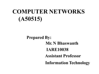
  • 1. COMPUTER NETWORKS (A50515) Prepared By: Mr. N Bhaswanth IARE10038 Assistant Professor Information Technology
  • 2. UNIT-I Overview of the Internet: Protocol, Layering Scenario, TCP/IP Protocol Suite: The OSI Model, Internet history standards and administration.Comparision of the OSI and TCP/IP reference model. Physical Layer: Guided transmission media, wireless transmission media. Data Link Layer-design issues, CRC Codes, Elementary Data link Layer protocols, sliding window protocol.
  • 3. PROTOCOLS AND STANDARDS Protocol A protocol is a set of rules that govern data communications. A protocol defines what is communicated, how it is communicated, and when it is communicated. The key elements of a protocol are syntax, semantics, and timing Syntax The term syntax refers to the structure or format of the data, meaning the order in which they are presented For example, a simple protocol might expect the first 8 bits of data to be the address of the sender, the second 8 bits to be the address of the receiver, and the rest of the stream to be the message itself. Semantics The word semantics refers to the meaning of each section of bits. For example, does an address identify the route to be taken or the final destination of the message? Timing The term timing refers to two characteristics: when data should be sent and how fast they can be sent. For example, if a sender produces data at 100 Mbps but the receiver can process data at only 1 Mbps, the transmission will overload the receiver and some data will be lost.
  • 4. Interfaces Between Layers The passing of the data and network information down through the layers of the sending device and back up through the layers of the receiving device is made possible by an interface between each pair of adjacent layers. Each interface defines the information and services a layer must provide for the layer above it. Well-defined interfaces and layer functions provide modularity to a network. As long as a layer provides the expected services to the layer above it, the specific implementation of its functions can be modified or replaced without requiring changes to the surrounding layers
  • 5. 2.4 An exchange using the OSImodel
  • 6. LAYERS IN THE OSI MODEL 1. Physicallayer The physical layer is responsible for movements of individual bits from one hop (node) to the next.
  • 7. The physical layer coordinates the functions required to carry a bit stream over a physical medium. It deals with the mechanical and electrical specifications of the interface and transmission medium. It also defines the procedures and functions that physical devices and interfaces have to perform for transmission to Occur The physical layer is also concerned with the following: •Physical characteristics of interfaces and medium The physical layer defines the characteristics of the interface between the devices andthe transmission medium. It also defines the type of transmission medium. Physicallayer
  • 8. Physical topology The physical topology defines how devices are connected to make a network. Devices can be connected by using a mesh topology, star topology, bus topology, ring topology or hybrid topology Transmission mode Physical layer defines direction of transmission between to systems Simplex mode : only one device can send and other can only receive. It is one way communication. Half duplex mode: Two devices can send and receive but not at the same time Full duplex mode: Two devices can send and receive at the same time
  • 9. 2.8 2. Data link layer The data link layer is responsible for moving frames from one hop (node) to the next.
  • 10. Access control When two or more devices are connected to the same link, data link layer protocols are necessary to determine which device has control over the link at any given time.
  • 11. The network layer is responsible for the delivery of individual packets from the source host to the destination host. 3.Networklayer
  • 12. Network Layer The network layer is responsible for the source-to-destination delivery of a packet, possibly across multiple networks (links). Whereas the data link layer oversees the delivery of the packet between two systems on the same network (links), the network layer ensures that each packet gets from its point of origin to its final destination. If the two systems are attached to different networks (links) with connecting devices between the networks (links), there is often a need for the network layer toaccomplish source-to-destination delivery
  • 13. Other responsibilities of the network layer include the following: Logical addressing. The physical addressing implemented by the data link layer handles theaddressing problem locally. If a packet passes the network boundary, we need another addressing system to help distinguish the source and destination systems. The network layer adds a header to the packet coming from the upper layerthat, among other things, includes the logical addresses of the sender and receiver. Routing When independent networks or links are connected to create internetworks(network of networks) or a large network, the connecting devices (called routers or switches) route or switch the packets to their final destination. One of the functions of the network layer is to provide this mechanism
  • 14. 2.13 4 .Transportlayer The transport layer is responsible for the delivery of a message from one process to another.
  • 15. Transport Layer A process is an application program running on ahost The transport layer, on the other hand, ensures that the whole message arrives intact and in order, overseeing both error control and flow control at the source-to-destination level.
  • 16. Other responsibilities of the transport layer include the following: Service-point addressing Computers often run several programs at the same time. For this reason, source to destination delivery means delivery not only from one computer to the next but also from a specific process (running program) on one computer to a specific process (running program) on the other The transport layer header must therefore include a type of address called a service-point address (or port address). The network layer gets each packet to the correct computer; the transport layer getsthe entire message to the correct process on that computer. Segmentation and reassembly A message is divided into transmittable segments, with each segment containing a sequence number These numbers enable the transport layer to reassemble the message correctly upon arriving at the destination and to identify and replace packets that were lost in transmission Connection control The transport layer can be either connectionless or connection oriented. A connectionless transport layer treats each segment as an independent packet and deliversit to the transport layer at the destination machine. A connection oriented transport layer makes a connection with the transport layer atthe destination machine first before delivering the packets. After all the data aretransferred ,the connection is terminated.
  • 17. Flow control Like the data link layer, the transport layer is responsible for flow control. However, flow control at this layer is performed end to end rather than across a single link. Errorcontrol Like the data link layer, the transport layer is responsible for error control. However, error control at this layer is performed process-to process rather than across a single link. The sending transport layer makes sure that the entire message arrives at the receiving transport layer without error(damage, loss, or duplication). Error correction is usually achieved through retransmission.
  • 18. 2.17 5.Sessionlayer The session layer is responsible for dialog control and synchronization.
  • 19. 2.18 6.Presentationlayer The presentation layer is responsible for translation, compression, and encryption.
  • 20. Presentation Layer The presentation layer is concerned with the syntax and semantics of theinformation exchanged between two systems.
  • 21. Specific responsibilities of the presentation layer include thefollowing: Translation Th.eprocesses (running programs) in two systems are usually exchanging information in the form of character strings, numbers, and so on. The information must be changed to bit streams before being transmitted. Because different computers use different encoding systems, the presentation layer is responsible for interoperability between these different encoding methods. The presentation layer at the sender changes the information from its sender-dependent format into a common format. The presentation layer at the receiving machine changes the common format into its receiver-dependent format Encryption To carry sensitive information, a system must be able to ensure privacy. Encryption means that the sender transforms the original information to another form and sends the resulting message out over the network Decryption reverses the original process to transform the message back to its original form Compression. Data compression reduces the number of bits contained in the information. Data compression becomes particularly important in the transmission of multimedia such as text, audio, and video
  • 22. 7.Applicationlayer The application layer is responsible for providing services to the user.
  • 23. Application Layer The application layer enables the user, whether human or software, to access the network. It provides user interfaces and support for services such as electronic mail, remote file access and transfer, shared database management, and other types of distributed information services. Figure 2.14 shows the relationship of the application layer to the user and the presentationlayer. Of the many application services available, the figure shows only three: XAOO (message handling services), X.500 (directory services), and file transfer, access, and management (FTAM). The user in this example employs XAOO to send an e-mail message
  • 24. Specific services provided by the application layer include thefollowing Network virtual terminal A network virtual terminal is a software version of a physical terminal, and it allows auser to log on to a remote host. To do so, the application creates a software emulation of a terminal at the remote host. The user's computer talks to the software terminal which, in turn, talks to the host, and vice versa. The remote host believes it is communicating with one of its own terminals and allows the user to log on. File transfer, access, and management This application allows a user to access files in a remote host (to make changes or read data), to retrieve files from a remote computer for use in the local computer, and to manage or control files in a remote computer locally. Mail services This application provides the basis for e-mail forwarding and storage. Directory services This application provides distributed database sources and access for global information about various objects and services.
  • 26. TCP/IP PROTOCOLSUITE The original TCP/IP protocol suite was defined as having fourlayers: 1 Host-to-Network Layer 2 Internet Layer 3 Transport Layer 4 Application Layer TCPIIP protocol suite is made of five layers: physical, data link, network, transport, and application. The first four layers provide physical standards, network interfaces, internetworking, and transport functions that correspond to the first four layers of the OSI model.
  • 27. Transport Layer Traditionally the transport layer was represented in TCP/IP by two protocols: TCP and UDP IP is a host-to-host protocol, meaning that it can deliver a packet from one physical deviceto another. UDP and TCP are transport level protocols responsible for delivery of a message froma process (running program) to another process. A new transport layer protocol, SCTP, has been devised to meet the needs of some newer applications. User Datagram Protocol(UDP) The User Datagram Protocol (UDP) is the simpler of the two standard TCP/IPtransport protocols. It is a process-to-process protocol that adds only port addresses, checksum error control, and length information to the data from the upper layer Transmission Control Protocol(TCP) The Transmission Control Protocol (TCP) provides full transport-layer services to applications TCP is a reliable stream transport protocol. A connection must be established between both ends of a transmission before either can transmit data. At the sending end of each transmission, TCP divides a stream of data into smaller units called segments. Each segment includes a sequence number for reordering after receipt, together with an acknowledgment number for the segments received. Segments are carried across the internet inside of IP datagrams. At the receiving end,TCP collects each datagram as it comes in and reorders the transmission based on sequence numbers.
  • 28. THE INTERNET A BriefHistory •A network is a group of connected communicating devices such as computers and printers. •In the mid-1960s, mainframe computers in research organizations were standalone devices. •The Advanced Research Projects Agency (ARPA) in the Department of Defense (DoD) was interested in finding a way to connect computers so that the researchers they funded could share their findings, thereby reducing costs and eliminating duplication of effort •In 1967, at an Association for Computing Machinery (ACM) meeting, ARPApresented its ideas for ARPANET, a small network of connected computers. •In 1972, Vint Cerf and Bob Kahn, both of whom were part of the core ARPANETgroup, collaborated on what they called the Internetting Project. Cerf and Kahn's landmark1973 paper outlined the protocols to achieve end-to-end delivery of packets. This paper on Transmission Control Protocol (TCP) included concepts such as encapsulation, the datagram, and the functions of a gateway.
  • 29. •Shortly thereafter, authorities made a decision to split TCP into two protocols: Transmission Control Protocol (TCP) and Internetworking Protocol (lP).. The internetworking protocol became known as TCP/IP The Internet Today The Internet has come a long way since the 1960s. The Internet today is not a simple hierarchical structure. It is made up of many wide- and local-area networks joined by connecting devices and switching stations. Today most end users who want Internet connection use the services of Internet service providers (lSPs). There are •international service providers, •national service providers, •regional service providers •local service providers. .
  • 31. Coaxial Cable coax has a central core conductor of solid or stranded wire (usually copper) enclosed in an insulating sheath, The outer metallic wrapping serves both as a shield against noise and as the second conductor, which completes the circuit. This outer conductor is also enclosed in an insulating sheath, and the whole cable is protected by a plasticcover
  • 32. Categories of Coaxial Cables RG – Radio Government
  • 33. Applications • Coaxial cable was widely used in analog telephone networks • In the traditional cable TV network,the entire network used coaxial cable • Another common application of coaxial cable is in traditional Ethernet LANs
  • 34. Fiber optics: Bending of light ray
  • 35. Fiber-Optic Cable • A fiber-optic cable is made of glass or plastic andtransmits signals in the form of light • Light travels in a straight line as long as it is moving througha single uniform substance • if the angle of incidence I is less than the critical angle, theray refracts and moves closer to the surface • If the angle of incidence is equal to the critical angle, thelight bends along the interface • If the angle is greater than the critical angle, the ray reflects and travels again in the densersubstance.
  • 37. Optical fiber • Optical fibers use reflection to guide light through achannel • .A glass or plastic core is surrounded by a cladding of less dense glass or plastic. • The difference in density of the two materials must be such that • a beam of light moving through the core is reflected off the cladding instead of being refracted into it
  • 38.
  • 39. Modes
  • 40. Multimode • Multimode is so named because multiple beams from a light source move through the core in different paths • In multimode step-index fiber, the density of the core remains constant from the center to the edges. • A beam of light moves through this constant density in a straight line until it reaches the interface of the core andthe cladding • step index refers to the suddenness of this change, which contributes to the distortion of the signal as it passes through the fiber.
  • 41. Multimode • multimode graded-index fiber, decreases this distortion of the signal through the cable • A graded-index fiber, therefore, is one with varying densities. Density is highest at the center of the core and decreases gradually to its lowest at the edge.
  • 42. Single-Mode • Single-mode uses step-index fiber and a highly focused source of light • that limits beams to a small range of angles, all close to the horizontal • propagation of different beams is almost identical, and delays are negligible. • All the beams arrive at the destination "together" and can be recombined with little distortion to the signal
  • 43. Applications • Fiber-optic cable is often found in backbone networks • cable TV companies use a combination of optical fiberand coaxial cable, thus creating a hybridnetwork • Local-area networks such as 100Base-FX network (FastEthernet) and 1000Base-X also use fiber-opticcable
  • 44. UNGUIDED MEDIA: WIRELESS • Unguided media transport electromagnetic waves without using a physical conductor • This type of communication is often referred to as wireless communication • Signals are normally broadcast through free space Electromagnetic Spectrum
  • 45. PropagationMethods Unguided signals can travel from the source to destination in several ways: ground propagation, sky propagation, and line-of-sightpropagation
  • 46. PropagationMethods In ground propagation, radio waves travel through the lowest portion of the atmosphere, hugging the earth In sky propagation, higher-frequency radio waves radiate upward into the ionosphere where they are reflected backto earth. In line-of-sight propagation, very high-frequency signals are transmitted in straight lines directly from antenna to antenna. Antennas must be directional, facing eachother,
  • 48. Wireless Transmission Waves 47 used for multicast/broadcast communications, such as radio and television used for unicast communication such as cellular telephones, satellite networks, and wireless LANs used for short-range communication in a closed area using line-of-sight propagation
  • 49. • Electromagnetic waves ranging in frequencies between 3 kHz and 1 GHz are called radiowaves. • Radio waves, for the most part, are omni directional. • When an antenna transmits radio waves, they are propagated in all directions • The radio waves transmitted by one antenna are susceptible to interference by another antenna that may send signals using the same frequency • Radio waves, particularly those of low and medium frequencies, can penetrate walls. Radio Waves
  • 50. Applications • AM and FM radio, television, maritime radio, cordless phones, and paging are examples of multicasting • Radio waves are used for multicast communications, such as radio and television, and paging systems.
  • 51. Microwaves • Electromagnetic waves having frequencies between I and 300 GHz are called microwaves • Microwaves are unidirectional. • Sending and receiving antennas need to bealigned • Microwave propagation is line-of-sight. • Very high-frequency microwaves cannot penetrate walls.
  • 52. Applications • Microwaves, due to their unidirectional properties, are very useful • when unicast (one-to-one) communication is needed • Microwaves are used for unicast communication such as cellular telephones • satellite networks, and wireless LANs.
  • 53. Infrared • Infrared waves, with frequencies from 300 GHz to 400THz can be used for short-range communication • Infrared waves, having high frequencies, cannot penetrate walls • Applications • Infrared signals can be used for short-range communication in a closed area using line-of-sightpropagation.
  • 54. Taxonomy of multiple-access protocols discussed in this chapter ALOHA CSMA CSMA/CD CSMA/CA FDMA TDMA CDMA Reservation Polling Tokenpassing
  • 55. UNIT-II Multiple Access Protocols- ALOHA, CSMA, Collision free protocols, Ethernet- Physical Layer, Ethernet Mac Sub layer, data link layer switching & use of bridges, learning bridges, spanning tree bridges, repeaters, hubs, bridges, switches, routers and gateways.
  • 56. MULTIPLE ACCESS • When nodes or stations are connected and use a common link, called a multipoint or broadcast link, we need a multiple-access protocol to coordinate access to the link. • The problem of controlling the access to the medium is similar to the rules of speaking in an assembly. • The procedures guarantee that the right to speak is upheld and ensure that : – Two people do not speak at the same time – do not interrupt each other – do not monopolize the discussion, and so on.
  • 58. RANDOM ACCESS • In random access or contention methods, no station is superior to another station and none is assigned the control over another. • No station permits, or does not permit, another station to send. • At each instance, a station that has data to send uses a procedure defined by the protocol to make a decision on whether or not to send. • This decision depends on the state of the medium (idle or busy)
  • 59. Two features give this method its name • First, there is no scheduled time for a station to transmit. • Transmission is random among the stations. That is why these methods are called random access. • Second, no rules specify which station should send next. • Stations compete with one another to access the medium. • That is why these methods are also called contention methods.
  • 60. RANDOM ACCESS • In a random access method, each station has the right to the medium without being controlled by any other station. • However, if more than one station tries to send, there is an access conflict- collision-and the frames will be either destroyed or modified.
  • 61. RANDOM ACCESS • Toavoid access conflict or to resolve it when it happens, each station follows a procedure that answers the following questions: – When can the station access the medium? – What can the station do if the medium is busy? – How can the station determine the success or failure of the transmission? – What can the station do if there is an access conflict?
  • 62. RandomAccess • The random access methods have evolved from a very interesting protocol known as ALOHA, which used a very simple procedure called multiple access (MA). • The method was improved with the addition of a procedure that forces the station to sense the medium before transmitting. • This was called carrier sense multiple access(CSMA).
  • 63. RandomAccess • This method later evolved into two parallel methods: – carrier sense multiple access with collision detection (CSMA/CD) – carrier sense multiple access with collision avoidance (CSMA/CA). • CSMA/CD tells the station what to do when a collision is detected. • CSMA/CA tries to avoid the collision.
  • 65. Pure aloha: • ALOHA was developed in 1970.it was designed for a radio LAN,but it cannot b used on any shared medium. • Pure aloha: original aloha • Idea is that each stn sends frame when ever it has frame to send. • Only one channel to share there is possibility of collision btw frames from different stations. • Pure aloha relies on ack from receiver.if ack does not arrive after time out period stn resends the frame. • If all stns try to resend their frames after time out,frames collide again.pure aloha dictates that when timeout period passes ,each stn waits for random amount of time bfore resending the frame.this time is called back off time .
  • 67. Procedure for ALOHAprotocol K: Number of attempts Tp : Maximum propagation time Tfr : Average transmission time for a frame TB : Back-off time (Ta=Rx Tp or R x Tfr (2 X Tp K=K+ 1 Kma, is normally 15
  • 68. Slottedaloha • Slotted aloha : was invented to improve the efficiency of pure aloha. • here we divide the time into slots tfr s and force the station to send only at the beginning of time slot. • Here if station misses to send at beginning of time slot it has to wait till next time slot. • But 2 or more stations try to send at same time slot, collision occurs.
  • 69. CSMA(carrier sense multiple access) • In CSMA every station must first listen to the medium before sending. • principle: sense before transmit or listen before talk. • It can reduce the possibility of collision but cannot avoid it because of propagation delay. • Tominimize the chance of collision and, therefore, increase the performance, the CSMA method was developed. Collision in CSMA
  • 70. CSMA(carrier sense multiple access) • The possibility of collision still exists because of propagation delay; when a station sends a frame, it still takes time (although very short) for the first bit to reach every station and for every station to sense it • a station may sense the medium and find it idle, only because the first bit sent by another station has not yet been received. • At time tI' station A senses the medium and finds it idle, so it sends a frame. • Station Z at right end of the medium senses the medium At time t2 (t2> tI)‘ and finds it idle because, at this time, the first bits from station A have not reached station Z, Station Z also sends a frame. • The two signals collide and both frames are destroyed.
  • 71. Persistencemethods • What should a station do if channel is busy? • What should a station do if channel is idle? • Non persistent:stn senses the line.if line is not idle,it waits random amount of time and then senses again. • 1-persistant:after stn finds line idle,it sends its frame immediately with probability 1. • P-persistent:after stn finds line idle then – 1)with probability p stn sends frame. – 2)with probability q=1-p,stn waits for beginning of next time slot and checks again. – A)if line is idle goto step1 b)If line is busy,it acts as though collision has occurred and uses backoff procedure.
  • 73. Carrier Sense Multiple Access with Collision Detection(CSMA/CD) • The CSMA method does not specify the procedure following a collision. Carrier sense multiple access with collision detection (CSMA/CD) augments the algorithm to handle the collision. • Csma/cd: In this mthd a stn monitors the medium after it sends the frame to see if the ftransmission was sucessful. • if so,it is finished, otherwise frame is sent again. • Toreduce the probabiliy of collision the second time, the station waits—it needs to back-off • It is reasonable that the station waits a little the first time, more if a collision occurs again, much more if it happens a third time, and so on. • the station waits an amount of time between 0 and 2 n*max_propagation_time-n is no of attempted transmission.
  • 75. CSMA/CA • Collisions are avoided through the use of CSMAICA's three strategies: – The inter-frame space or gap(IFS or IFG) – The contention window – Acknowledgments
  • 76. CSMA/CA • Timing in csma/ca: size: binary exponential found idle continuouslysense IFS busy contention window sendframe timeout time
  • 77. CSMA/CA- Inter-frame Space (IFS) • When an idle channel is found, the station does not send immediately. It waits for a period of time called the inter- frame space or IFS. • Even though the channel may appear idle when it is sensed, a distant station may have already started transmitting. • The distant station's signal has not yet reached this station. • The IFS time allows the front of the transmitted signal by the distant station to reach this station • If after the IFS time the channel is still idle, the station can send.
  • 78. CSMA/CA contentionwindow • The contention window is an amount of time divided into slots. • A station that is ready to send chooses a random number of slots as its wait time. • The number of slots in the window changes according to the binary exponential back-off strategy. • This means that it is set to one slot the first time and then doubles each time the station cannot detect an idle channel after the IFS time.
  • 79. Acknowledgment • With all these precautions, there still may be a collision resulting in destroyed data. • In addition, the data may be corrupted during the transmission. • The positive acknowledgment and the time-out timer can help guarantee that the receiver has received the frame.
  • 82. 802.3 MAC frame • Preamble:it alerts the receiver to coming frame and enables synchronization.it is added at physical layer • Sfd:signals beginning of frame.sfd warns stns that this is last chance for sync.the last bits 11 alerts the recvr that next field is destination address. • Data:minimum 46 and maximum 1500 bytes • Crc: crc-32 is used • Dsap:destination service access point.
  • 83. Minimum and maximum length • Min length restriction is req for correct opn of csma/cd.of 64 bytes,header and trailer length is 18 bytes.so data 46 bytes • Max length is 1518,of which header and trailer length is 18 bytes .so data 1500bytes • Max restriction bcoz memory was expensive and it prevents 1 stn from monopolizing shared medium,blocking other stns that have data to send.
  • 84. Categories of traditional Ethernet • All standard implementations use digital signaling at 10 mbps.at sender data are converted to digital signal using manchester scheme • Bus,thick coaxial bus,thin coaxial star,utp star,fiber
  • 85. Connection of a station to the medium using 10Base5 Thick ethernet • First implementation is called 10base5,thick ethernet or thicknet.uses bus topology with external tranceiver (transmitter/receiver) connected via a tap to thick coaxial cable. Can’t bend • 10 base 5(10 Mbps baseband 500m) • Tranceiver is responsible for transmitting,receiving and detecting collisions. . collision occurs in coaxial cable
  • 86. Connection of stations to the medium using 10Base2 Thin Ethernet • Second implementation is called 10base2,thin ethernet or cheapernet.uses bus topology with thinner and flexible cable.can bend. • Tranceiver is part of n/w interface card,installed inside stn. • 10 base 2(10 Mbps baseband 185m) • Installation is simpler. collision occurs in coaxial cable
  • 87. Connection of stations to the medium using 10Base-T Twisted pair Ethernet • Third implementation is called 10baseT, Twisted pair ethernet.uses physical star topology .stns are connected to a hub via 2 pairs of twisted cable.collisions occur in hub.max length is 100m to minimise effect of attenuation. • 10 base T(10 Mbps baseband Twisted pair)
  • 88. Connection of stations to the medium using 10Base-FL Fiber Ethernet • Uses star topology. stns are connected to a hub via 2 pairs of fiber optic cable.upto 2000 m • 10 base T(10 Mbps baseband fiber optic pair)
  • 89. Fast Ethernet physical layer Fast Ethernet • It is designed to compete with lan protocols such as fddi or fiber channel.it is backward compatible with stnd Ethernet. • Goals: 1)upgrade the datarate to 100mbps • 2) compatible with stnd Ethernet. • 3)keep same 48 bit address. • 4)keep same frame format. • 5)keep same min and max lengths. • Mac sublayer • Keep mac layer untouched,but drop bus topology and consider star topology- half & full duplex.in half duplex,stns r connected via hub and acess mthd is csma/cd.in full duplex,connection is made via switch with buffers at each port no need of acess mthd as csma/cd. • Autonegotiation: it allows a stn or a hub a range of capabilities.it allows 2 devices to negotiate the mode r data rate of opn.
  • 90. Fast Ethernet implementations • 2 wires category 5 UTP 2 wires,fiber 4 wires category 3 UTP
  • 91. 100Base-TX implementation • It uses 2 pairs of twisted pair cables. • It uses mlt3 scheme since it has good performance.since mlt3 is not self synchronous,4B/5B encoding is uesd for bit synchronization by prventing long sequence of 0’s and 1’s.this crates a datarate of 125 mbps,which is fed into mlt3 for encoding
  • 92. Encoding and decoding in 100Base-TX
  • 93. 100Base-FX implementation • It uses 2 pairs of fiber optic cables. fiber optic cables can easily handle high bandwidth requirements by using encoding schemes. • Nrz-I has bit synchronization prblm for long seq of 0’s.designers use 4b/5b block encoding.
  • 94. Gigabit Ethernet implementations • In traditional approach we keep minimum leghth of frame as 512 bits.so slot time in gigabit ethernet is 512 bitsX1/1000micro secs.reduced slot time means collision is detected 100 times earlier. 2 wire,long wave fiber 2wire,copper(stp) 4 wireutp • 2wire short wave fiber
  • 95. 1000Base-X implementation • 1000 base-T was designed in response to those users who had already installed this wiring for other pursposes such as fast ethernet. • Gigabit thernet cannot use manchestor encoding scheme bcoz it involves very high bandwidth.8b/10b block encoding is used.
  • 99. Connecting devices • LANs do not normally operate in isolation. They are connected to one another or to the Internet. • Toconnect LANs, or segments of LANs, we use connecting devices. • Connecting devices can operate in different layers of the Internetmodel.
  • 100. The five categories contain devices which can be defined as • 1.Those which operate below the physical layer such as a passive hub. • 2.Those which operate at the physical layer (a repeater or an active hub). • 3.Those which operate at the physical and data link layers (a bridge or a two- layer switch). • 4. Those which operate at the physical, data link, and network layers (a router or a three-layer switch). • 5. Those which can operate at all five layers (a gateway).
  • 102. Passive Hubs • A passive hub is just a connector. It connects the wires coming from different branches. • The hub is the collision point where the signals coming from different stations collide. • This type of a hub is part of the media • Its location in the Internet model is below the physical layer.
  • 103. Repeaters • A repeater is a device that operates only in the physical layer. • Signals that carry information within a network can travel a fixed distance before it becomes too weak or corrupted • A repeater receives a signal and, regenerates the original bit pattern. • The repeater then sends the refreshedsignal. • A repeater can extend the physical length of a LAN.
  • 105. Function of a repeater •Location of repeater on a link is vital. • A repeater must be placed so that a signal reaches it before any noise changes meaning of bit.
  • 106. Active Hubs • An active hub is actually a multipart repeater. • It is normally used to create connections between stations in a physical star topology. • Hubs can also be used to create multiple levels of hierarchy • The hierarchical use of hubs removes the length limitation of 10Base-T (100 m).
  • 108. Bridges • A bridge operates in both the physical and the data link layer. • As a physical layer device, it regenerates the signal it receives. • As a data link layer device, the bridge can check the physical (MAC) addresses (source and destination) contained in the frame.
  • 109. Bridge
  • 110. Switches • switch can mean two different things. – A two-layer switch – A three-layer switch • A three-layer switch is used at the network layer; it is a kind of router. • The two-layer switch performs at the physical and data link layers.
  • 111. A two –layer switches • A two-layer switch is a bridge, a bridge with many ports and a design that allows better (faster) performance. • makes a filtering decision based on the MAC address of the frame it received • It can have a buffer to hold the frames for processing. • It can have a switching factor that forwards the frames faster. Some new two-layer switches, called cut- through switches, have been designed to forward the frame as soon as they check the MAC addresses in the header of the frame.
  • 112. Routers • A router is a three-layer device that routes packets based on their logical addresses (host- to-host addressing). • A router normally connects LANs and WANs in the Internet and has a routing table that is used for making decisions about the route.
  • 114. A three –layer switches • A three-layer switch is a router, but a faster and more sophisticated. • The switching fabric in a three-layer switch allows faster table lookup and forwarding
  • 115. Gateway • A gateway is normally a computer that operates in all five layers of the Internet or seven layers of OSI model. • A gateway takes – – an application message – reads it – interprets it. • This means that it can be used as a connecting device between two internetworks that use different models.
  • 116. UNIT-III Network Layer: Network Layer Design issues, store and forward packet switching connection less and connection oriented networks-routing algorithms-optimality principle, shortest path, flooding, Distance Vector Routing, Count to Infinity Problem, Hierarchical Routing, Congestion control algorithms, admission control.
  • 119. RIP • The routing information protocol (RIP) is an interior routing protocol used inside an autonomous system. • It is a very simple protocol based on distance vector routing which uses the Bellman-Ford alg for calculating the routing tables.
  • 120. Distance vector routing • In distance vector routing each router periodically shares its knowledge about the entire internet with its neighbors. • In distance vector routing, the least-cost route between any two nodes is the route with minimum distance. • In this protocol, as the name implies, each node maintains a vector (table) of minimum distances to every node. • The table at each node also guides the packets to the desired node by showing the next stop in the route (next- hop routing). • We can think of nodes as the cities in an area and the lines as the roads connecting them. • A table can show a tourist the minimum distance between cities.
  • 124. Traffic descriptors • In cc control we try to avoid traffic congestion.in qos we try to create an appropriate envt for traffic. • Traffic descriptor r qualitative values that represent data flow. • Avg bit rate is no. of bits sent during period of time divided by no. of secs. • Peak data rate defines max data rate of traffic. • Max length of time traffic is generated at peak rate is max burst size.
  • 125. Trafficprofiles • a data flow can have one of the following traffic profiles: – constant bit rate, – variable bit rate, – or bursty
  • 126. Constant-bit-rate traffic A constant-bit-rate (CBR), or a fixed-rate, traffic model has a data rate that does not change. In this type of flow, the average data rate and the peak data rate are the same.
  • 127. Variable-bit-rate (VBR) • In the variable-bit-rate (VBR) category, the rate of the data flow changes in time, with the changes smooth instead of sudden and sharp. • In this type of flow, the average data rate and the peak data rate are different. • The maximum burst size is usually a small value.
  • 129. Bursty data • In the bursty data category, the data rate changes suddenly in a very short time. • It may jump from zero, for example, to 1 Mbps in a few microseconds and vice versa. • The average bit rate and the peak bit rate are very different values in this type of flow. • The maximum burst size is significant. This is the most difficult type of traffic for a network to handle because the profile is very unpredictable.
  • 130.
  • 131. Congestion • Congestion in a network may occur if the load on the network – The number of packets sent to the network-is greater than the capacity of the network. – capacity : The number of packets a network can handle. • Congestion control refers to the mechanisms and techniques to control the congestion and keep the load below the capacity.
  • 132. 3 steps • 1. The packet is put at the end of the input queue while waiting to be checked. • 2. The processing module of the router removes the packet from the input queue once it reaches the front of the queue and uses its routing table and the destination address to find the route. • 3. The packet is put in the appropriate output queue and waits its turn to be sent.
  • 133. Packet delay and network load • CC involves 2 factors that measure the performance of n/w -delay & throughput.
  • 134. Throughput versus network load • Throughput is no. of packets passing through n/w in unit of time.
  • 135. Congestioncontrol • Congestion control refers to techniques and mechanisms that can either prevent congestion, before it happens, or remove congestion, after it has happened. • In general, we can divide congestion control mechanisms into two broad categories: – open-loop congestion control (prevention) – and closed-loop congestion control (removal)
  • 136.
  • 137. Open-loop Congestion Control • In open-loop congestion control, policies are applied to prevent congestion before it happens. • In these mechanisms, congestion control is handled by either the source or the destination.
  • 138. Retransmission Policy • If the sender feels that a sent packet is lost or corrupted, the packet needs to be retransmitted. • Retransmission in general may increase congestion in the network.
  • 139. Window Policy • The type of window at the sender may also affect congestion. • The Selective Repeat window is better than the Go-Back-N window for congestion control. • In the Go-Back-N window, when the timer for a packet times out, several packets may be resent • The Selective Repeat window, on the other hand, tries to send the specific packets that have been lost or corrupted.
  • 140. Acknowledgment Policy • The acknowledgment policy imposed by the receiver may also affect congestion. • If the receiver does not acknowledge every packet it receives, it may slow down the sender and help prevent congestion. Discarding Policy • A good discarding policy by the routers may prevent congestion and at the same time may not harm the integrity of the transmission.
  • 141. Admission Policy • An admission policy, which is a quality-of-service mechanism, can also prevent congestion in virtual-circuit networks. • Switches in a flow first check the resource requirement of a flow before admitting it to the network. • A router can deny establishing a virtual circuit connection if there is congestion in the network or if there is a possibility of future congestion.
  • 142. • Closed-loop congestion control mechanisms try to alleviate congestion after it happens. • back pressure ->in which congested node stops recvng data frm immediate upstream • Choke packet:is a packet sent by a node to source to inform it of congestion. • Implicit signaling:no communication btw source and congested nodes.source guesses that there is congestion somewhere in n/w. • Explicit signaling:source that experiences congestion can explicitly send a signal to source r destn. Closed loop
  • 143.
  • 144. Congestion Window • The sender's window size is determined not only by the receiver but also by congestion in the network. • The sender has two pieces of information: – The receiver-advertised window size and – The congestion window size. • The actual size of the window is the minimum of these two. • Actual window size= minimum (rwnd, cwnd)
  • 145. Congestion Avoidance • In tcp it uses 2 policies – slow start and additive increase – multiplicative decrease • 1)slow start:exponential increase: alg is based on idea that size of congestion window starts with 1 max segment size(MSS). • MSS is determined during connection establishment. • size of window increases 1 MSS each time ack is sent. • window starts slowly and grows exponentially. • additive increase:to avoid congestion bfore it happens,one must slow down itsexponential growth. • when size of congestion window reaches slow start threshold,slow start phase stops and additive phase begins. • In this algorithm, each time the whole window of segments is acknowledged(one round), the size of the congestion window is increased by1 • 2)multiplicative decrease:if congestion occurs,congestion window size must b decreased.size of threshold must be dropped to one half.
  • 147. If we look at the size of cwnd in terms of rounds we find that the rate is exponential as shown below: • Start ..... cwnd=l • After round 1 ..... cwnd=21 =2 • After round 2 ..... cwnd=22 =4 • After round 3 ..... cwnd=23 =8
  • 149. If we look at the size of cwnd in terms of rounds, we find that the rate is additive as shown below: • Start • After round 1 • After round 2 • After round 3 • ............ ............ • cwnd=l • cwnd= 1+ 1 =2 • cwnd=2+ 1 =3 • cwnd=3+ 1 =4
  • 150. Multiplicative Decrease • If congestion occurs, the congestion window size must be decreased. • The only way the sender can guess that congestion has occurred is by the need to retransmit a segment. • The strategy says if a time-out occurs, the threshold must be set to one-half of the last congestion window size, and the congestion window size from 1 again.
  • 152. Congestion Control in frame relay • Congestion in a Frame Relay network decreases throughput and increases delay. • A high throughput and low delay are the main goals of the Frame Relay protocol. • Frame Relay does not have flow control. CongestionAvoidance – For congestion avoidance, the Frame Relay protocol uses 2 bits in the frame to explicitly warn the source and the destination of the presence of congestion. – BECN – FECN
  • 153. Backward explicit congestion notification(BECN): • A bit warns sender of congestion in n/w. • switch uses response frames from receiver or switch can use predefined connection(DLCI) to send special frames for this specific purpose. • The sender can respond to this warning by simply reducing the data rate.
  • 154. Forward explicit congestion notification(FECN) • A Bit is used to warns receiver of congestion in n/w. • The receiver can respond to this warning by simply can delay the acknowledge thus forcing the sender to slow down rate.
  • 155. Four cases of congestion
  • 156. Quality of Service Flow Characteristics Flow Classes
  • 157. QUALITY OF SERVICE • four types of characteristics are attributed to a flow: – Reliability – delay, – Jitter – bandwidth
  • 158. Reliability • Reliability is a characteristic that a flow needs. • Lack of reliability means losing a packet or acknowledgment, which entails retransmission. • However, the sensitivity of application programs to reliability is not the same. • For example, it is more important that electronic mail, file transfer, and Internet access have reliable transmissions than telephony or audio conferencing
  • 159. delay • Source-to-destination delay is another flow characteristic. • Again applications can tolerate delay in different degrees. • In this case, telephony, audio conferencing, video conferencing, and remote log- in need minimum delay, while delay in file transfer or e-mail is less important
  • 160. Jitter • Jitter is the variation in delay for packets belonging to the same flow. • For example, if four packets depart at times 0, 1, 2, 3 and arrive at 20, 21, 22, 23, all have the same delay, 20 units of time. • On the other hand, if the above four packets arrive at 21, 23, 21, and 28, they will have different delays: 21,22, 19, and 24.
  • 161. Bandwidth • Different applications need different bandwidths. • For In video conferencing need more bandwidth • in an e-mail it may need less bandwidth
  • 162. Techniques to Improve QoS Scheduling Traffic Shaping Resource Reservation Admission Control
  • 163. Flow characteristics • reliability Lack of reliability means losing a packet or acknowledgment, which entails retransmission. • delay Applications can tolerate delay in different degrees. • delay in file transfer or e-mail is less important.
  • 164. Jitter • Jitter is the variation in delay for packets belonging to the same flow. • For example, if four packets depart at times 0, 1, 2, 3 and arrive at 20, 21, 22, 23, all have the same delay, 20 units of time. • On the other hand, if the above four packets arrive at 21, 23, 21, and 28, they will have different delays: 21,22, 19, and 24. • For applications such as audio and video, the first case is completely acceptable; the second case is not. • For these applications, it does not matter if the packets arrive with a short or long delay as long as the delay is the same for all packets. For this application, the second case is not acceptable. • Jitter is defined as the variation in the packet delay. High jitter means the difference between delays is large; low jitter means the variation is small.
  • 165. Bandwidth applications need different • Different bandwidths. • In video conferencing we need to send millions of bits per second to refresh a color screen so it needs more bandwidth • while the total number of bits in an e-mail may not reach even a million so it needs less bandwidth
  • 166. TECHNIQUES TO IMPROVE QoS • four common methods to improve QoS – scheduling, – traffic shaping, – admission control, – resource reservation.
  • 167. FIFO queue • Several scheduling techniques are designed to improve QoS. • FIFO queing:in FIFO queue,packets wait in a buffer until node is ready to process them
  • 168. Priority Queuing • In priority queuing, packets are first assigned to a priority class. • Each priority class has its own queue. • The packets in the highest-priority queue are processed first. • Packets in the lowest-priority queue are processed last.
  • 170. Weighted fair Queuing • In this technique, the packets are still assigned to different classes and admitted to different queues. • The queues, are weighted based on the priority of the queues; higher priority means a higher weight. • The system processes packets in each queue in a round-robin fashion with the number of packets selected from each queue based on the corresponding weight. • For example, if the weights are 3, 2, and 1, three packets are processed from the first queue, two from the second queue, and one from the third queue.
  • 172. Traffic Shaping • Traffic shaping is a mechanism to control the amount and the rate of the traffic sent to the network. • Two techniques can shape traffic: – leaky bucket and – token bucket.
  • 173. Leaky bucket In all, the host has sent 30 Mbits of data in 1Os. The leaky bucket smooths the traffic by sending out data at a rate of 3 Mbps during the same 10 s.
  • 174. leaky bucket implementation • A FIFO queue holds the packets. If the traffic consists of fixed-size packets (e.g., cells in ATM networks), the process removes a fixed number of packets from the queue at each tick of the clock. • If the traffic consists of variable-length packets, the fixed output rate must be based on the number of bytes or bits. • The following is an algorithm for variable-length packets: 1. Initialize a counter to n at the tick of the clock. 2. If n is greater than the size of the packet, send the packet and decrement the counter by the packet size. Repeat this step until n is smaller than the packet size. 3. Reset the counter and go to step 1.
  • 176. Token bucket • Leaky bucket is very restrictive. • Doesn't credit idle host. • token bucket alg allows idle hosts to accumulate credit for future in the form of tokens. • For each tick of clock, system sends n tokens to bucket. • System removes 1 token for every cell of data sent. • Implemented by using counter-initialized to 0 & incremented by 1 each time tokenadded • Each time a unit of data is sent, the counter is decremented by 1. • When the counter is zero, the host cannot send data.
  • 178. The token bucket allows bursty traffic at a regulated maximum rate. Note:
  • 180. Integrated Services • How can we implement a flow based model over connectionless protocol? • Solution is signaling protocol to run over IP that provides signaling mechanism for making reservation. • This protocol resource reservation protocol. • Flow specification has 2 parts- – rspec(resorce specification) buffer, bandwidth – tspec(traffic specification) traffic characterization • Admission: After router rcvs flow specn frm appn it decides to admit or deny service. • Service classes : guaranteed service is designed for realtime traffic that needs minimum end to end delay • Controlled load service access: designed for appns that can accept some delays,but they are sensitive to overloaded n/w.ex:file transfer,email,internet access.
  • 181. RSVP • RSVP is a signaling protocol to help IP to create a flow and consequently make resource reservation. • Multicast Trees – designed for multicasting – also used for unicasting because unicasting is just a special case of multicasting with only one member in the multicastgroup • Receiver-Based Reservation: • Rsvp messages :path &rsvp • Path msgs:rcvrs in flow make reservation in rsvp.but they don’t know the path traveled by packets bfore reservation is made. • path is needed for reservation .to solve it rsvp uses path msgs
  • 182. RSVP
  • 184. Reservation styles When there is more than one flow the router needs to make reservation to accommodate all of them • In wf,router creates single reservation for all senders. reservation is based on larger request. • In ff, router creates distinct reservation for flow. • In se, router creates single reservation which can be shared by set of flows.
  • 185. Differentiated Services is a class-based QoS model designed for IP. Note:
  • 186. DS field • In diffserv each packet contains DS field whose value is set at the boundary of n/w by host or first router designated as boundary router. • Differentiated services core point (DSCP) defines per hop behviour. • cu-currentlyunused. • Toimplement diffserv DS node uses traffic conditioners such as – Meters – Markers – shapers. • Meters check to see if incmg flow matches negotiated traffic profile • Marker can mark a packet that is using best effort delivery. • Shaper uses infn recvd from meter to reshape the traffic • Dropper works as a shaper with no buffer ,discards the packets.
  • 188. QoS in Switched Networks QoS in Frame Relay QoS in ATM
  • 189. QoS IN SWITCHED NETWORKS • QoS in FrameRelay • Four different attributes to control traffic have been devised in FrameRelay: – access rate, – committed burst size Be' – committed information rate (CIR), – excess burst size Be' • For every connection access rate which depends on the bw of channel is defined. • Committed burst size Bc: maximum no. of bits in predefined time that n/w is committed to transfer without discarding any frame r setting de bit. • Committed info rate(CIR) defines avg rate in bits per sec. – CIR=Bc/T • Excess burst size Be: max no. of bits in excess of bc that a user can send during a predefined time.
  • 190. User rate in relation to Bc and Bc + Be
  • 191. QoS in ATM • The QoS in ATMis based on the – class, – user-related attributes, – and network-related attributes
  • 192. ATM:Service classes • CBR designed for custmers who need real time audio,video services. • VBR class is divided into two subclasses: real-time • (VBR-RT) and non-real-time (VBR-NRT). • VBR-RT is designed for those users who need real-time services • VBR-NRT is designed for those users who do not need real-time services • Abr (avilable bit rate)delivers cells at minimum rate. • Unspecified bit rate(UBR) is a best effort delivery service that does not guarantee anything
  • 193. Relationship of service classes to the total capacity
  • 194. UNIT-IV SYLLABUS: Internetworking: Tunneling, Internetwork Routing, Packet fragmentation, IPv4, IPv6 Protocol, IP addresses CIDR, IMCP, ARP, RARP, DHCP. Transport Layer: Services provided to the upper layers elements of transport protocol- addressing connection establishment, connection release, Crash Recovery.
  • 196. Links in an internetwork
  • 197. Network layer in an internetwork
  • 198. Network layer at the source
  • 199. Network layer at a router
  • 200. Network layer at the destination
  • 201. IPv4 • The Internet Protocol version 4 (IPv4) is the delivery mechanism used by the TCP/IPprotocols. • IPv4 is an unreliable and connectionless datagram protocol-a best-effort delivery service. • The term best-effort means that IPv4 provides no error control or flow control (except for error detection on the header). • IPv4 assumes the unreliability of the underlying layers and does its best to get a transmission through to its destination, but with no guarantees. • If reliability is important, IPv4 must be paired with a reliable protocol such as TCP.
  • 203. A brief description of each field is in order. • Version (VER). This 4-bit field defines the version of the IPv4 protocol. • Header length (HLEN). This 4-bit field defines the total length of the datagram header in 4-byte words. • This field is needed because the length of the header is variable (between 20 and 60 bytes). • Differentiated services: • This field defines the class of the datagram for quality-of – service purposes. • Total length: this field defines the total length(header plus data) of the IP datagram in bytes. • Identification, flag, and offset:
  • 204. A brief description of each field is in order. • Time to live: A datagram has a limited lifetime in its travel through an internet. • This field was originally designed to hold a timestamp, which was decremented by each visited router. • The datagram was discarded when the value became zero. • This field is used mostly to control the maximum number of hops (routers) visited by the datagram. • When a source host sends the datagram, it stores a number in this field. This value is approximately 2 times the maximum number of routes between any two hosts. • Each router that processes the datagram decrements this number by 1. If this value, after being decremented, is zero, the router discards the datagram. • Protocol. This 8-bit field defines the higher-level protocol that uses the services of the IPv4 layer. An IPv4 datagram can encapsulate data from several higher-level protocols such as TCP, UDP, ICMP, and IGMP.
  • 205.
  • 206. Fragmentation • A datagram can travel through different networks. Each router de-capsulates the IPv4 datagram from the frame it receives, processes it, and then encapsulates it in another frame. • The format and size of the received frame depend on the protocol used by the physical network through which the frame has just traveled. • The format and size of the sent frame depend on the protocol used by the physical network through which the frame is going to travel. • For example, if a router connects a LAN to a WAN, it receives a frame in the LAN format and sends a frame in the WAN format.
  • 207. Maximum Transfer Unit (MTU) • Each data link layer protocol has its own frame format in most protocols. • One of the fields defined in the format is the maximum size of the data field. • In other words, when a datagram is encapsulated in a frame, the total size of the datagram must be less than this maximum size
  • 208. The value of the MTU depends on the physical network protocol.
  • 209.
  • 210. • To make the IPv4 protocol independent of the physical network, the designers decided to make the maximum length of the IPv4 datagram equal to 65,535 bytes. • When a datagram is fragmented, each fragment has its own header with most of the fields repeated, but with some changed. • A fragmented datagram may itself be fragmented if it encounters a network with an even smaller MTU In IPv4, a datagram can be fragmented by the source host or any router in the path • The reassembly of the datagram, however, is done only by the destination host because each fragment becomes an independent datagram.
  • 211. • Figure shows a datagram with a data size of 4000 bytes fragmented into three fragments. • The bytes in the original datagram are numbered 0 to 3999. • The first fragment carries bytes 0 to 1399. • The offset for this datagram is 0/8 =O. • The second fragment carries bytes 1400 to 2799; the offset value for this fragment is 1400/8 = 175. • Finally, the third fragment carries bytes 2800 to 3999. The offset value for this fragment is 2800/8 =350. • Remember that the value of the offset is measured in units of 8 bytes. • This is done because the length of the offset field is only 13 bits and cannot represent a sequence of bytes greater than 8191. • This forces hosts or routers that fragment datagram's to choose a fragment size so that the first byte number is divisible by 8.
  • 213. IPV4 deficiencies • IPV4 has a two-level address structure categorized into five classes. The use of address space is inefficient. • The internet must accommodate real-time audio and video transmission. This type of transmission requires minimum delay strategies and reservation of resources not provided in the ipv4 design. • The internet must accommodate encryption and authentication of data for some application. No security mechanism was provided by IPv4
  • 216. Abbreviated address with consecutive zeros
  • 217. Format of an IPv6 datagram
  • 218. Comparison of network layers in version 4 and version 6
  • 223. ARP-INTRODUCTION • An internet is made of a combination of physical networks connected by internetworking devices such as routers. • A packet starting from a source host may pass through several different physical networks before finally reaching the destination host. • The hosts and routers are recognized at the network level by their logical (IP) addresses. • A physical address is a local address. It must be unique locally, but is not necessarily unique universally. • It is called a physical address because it is usually (but not always) implemented in hardware. • An example of a physical address is the 48-bit MAC address in the Ethernet protocol, which is imprinted on the NIC installed in the host or router
  • 224. ARP • The physical address and the logical address are two different identifiers. • A packet at a network layer such as IP may pass through different physical networks such as Ethernet and LocalTalk (Apple) • This means that delivery of a packet to a host or a router requires two levels of addressing: – logical and – physical.
  • 225. MAPPING • We need to be able to map a logical address to its corresponding physical address and vice versa. • Toimplement these changes, a static mapping table must be updated periodically. This overhead could affect network performance. • These can be done by using either • static or • dynamic mapping.
  • 226. STATICMAPPING • Static mapping involves in the creation of a table that associates a logical address with a physical address. • This table is stored in each machine on the network. Each machine that knows, the IP address of another machine but not its physical address • This has some limitations because physical addresses may change in the following ways: – 1. A machine could change its NIC, resulting in a new physical address. – 2. In some LANs, such as LocalTalk, the physical address changes every time the computer is turned on. – 3. A mobile computer can move from one physical network to another, resulting in a change in its physical address • Toimplement these changes, a static mapping table must be updated periodically. This overhead could affect network performance.
  • 227. Mapping Logical to Physical Address: ARP • In dynamic mapping each time a machine knows one of the two addresses (logical or physical), it can use a protocol to find the other one. • Two protocols have been designed to perform dynamic mapping: – Address Resolution Protocol(ARP) – Reverse Address Resolution(RARP)
  • 228. ARP • It maps an IP address to a MAC address • RARP maps a MAC address to an IP address • ARP associates an IP address on a link is identified by a physical or station address that is usually • Anytime a host or a router has an IP datagram to send to another host or router, it has the logical (IP) address of the receiver imprinted on the NIC • This means that the sender needs the physical address of the receiver. • The host or the router sends an ARP query packet. The packet includes the physical and IP addresses of the sender and the IP address of the receiver. • Because the sender does not know the physical address of the receiver, the query is broadcast over the network • Every host or router on the network receives and processes the ARP query packet, but only the intended recipient recognizes its IP address and sends back an ARP response packet. The response packet contains the recipient's IP and physical addresses.
  • 233. Encapsulation of ARPpacket An ARP packet is encapsulated directly into a data link frame.
  • 235. • Example • A host with IP address 130.23.43.20 and physical address B2:34:55: 10:22: 10 has a packet to send to another host with IP address 130.23.43.25 and physical address A4:6E:F4:59:83:AB (which is unknown to the first host). The two hosts are on the same Ethernet network. Show the ARP request and reply packets encapsulated in Ethernet frames. • Solution • Figure shows the ARP request and reply packets. Note that the ARP data field in this case is 28 bytes, and that the individual addresses do not fit in the 4-byte boundary. • That is why we do not show the regular 4-byte boundaries for these addresses.
  • 236.
  • 237. ICMP • The IP protocol also lacks a mechanism for host and management queries. • A host sometimes needs to determine if a router or another host is alive. • And sometimes a network administrator needs information from another host or router. • The Internet Control Message Protocol (ICMP) has been designed to compensate for the above two deficiencies. • It is a companion to the IP protocol • The value of the protocol field in the IP datagram is 1 to indicate that the IP data are an ICMP message.
  • 239. ICMP Types of Messages Error Reporting Query
  • 241. Destination Unreachable • When a router cannot route a datagram or a host cannot deliver a datagram, the datagram is discarded and the router or the host sends a destination-unreachable message back to the source host that initiated the datagram. • Note that destination-unreachable messages can be created by either a router or the destination host.
  • 242. source-quench • When a router or host discards a datagram due to congestion, it sends a source- quench message to the sender of the datagram. • This message has two purposes. • First, it informs the source that the datagramhas been discarded. • Second, it warns the source that there is congestion somewhere in the path and thatthe source should slow down (quench) the sending process.
  • 243. Time Exceeded • When the time-to-live value reaches 0, after decrementing, the router discards the datagram. • First:when the datagram is discarded, a time- exceeded message must be sent by the router to the original source. • Second, a time-exceeded message is also generated when not all fragments that make up a message arrive at the destination host within a certain time limit.
  • 244. Parameter Problem • Any ambiguity in the header part of a datagram can Create serious problems as the datagram travels through the Internet. • If a router or the destination host discover an ambiguous or missing value in any field of the datagram, it discards the datagram and sends a parameter-problem message back to the source
  • 245. Redirection message • If Any host may send a datagram, which is destined for another network, to the wrong router. • In this case, the router that receives the datagram will forward the datagram to the correct router. • However, to update the routing table of the host, it sends a redirection message to the host
  • 247. Echo Request and Reply • The echo-request and echo-reply messages are designed for diagnostic purposes. • Network managers and users utilize this pair of messages to identify network problems. • The combination of echo-request and echo- reply messages determine whether two systems (hosts or routers) can communicate with each other.
  • 248. Timestamp Request and Reply • Two machines (hosts or routers) can use the timestamp request and timestamp reply messages to determine the round-trip time needed for an IP datagram to travel between them. • It can also be used to synchronize the clocks in two machines.
  • 249. Address-Mask Request and Reply • A host may know its IP address, but it may not know the corresponding mask. • For example, a host may know its IP address as 159.31.17.24, but it may not know that the corresponding mask is /16. • Toobtain its mask, a host sends an address- mask-request message to a router on the LAN.
  • 250. Router Solicitation and Advertisement • A host that wants to send data to a host on another network needs to know the address of routers connected to its own network. • Also, the host must know if the routers are alive and functioning. • The router-solicitation and router-advertisement messages can help in this situation. • A host can broadcast (or multicast) a router-solicitation message. • The router or routers that receive the solicitation message broadcast their routing information using the router-advertisement message.
  • 253. • The data link layer is responsible for delivery of frames between two neighboring nodes over a link. This is called node-to-node delivery. • The network layer is responsible for delivery of datagrams between two hosts. This is called host-to-host delivery. • Communication on the Internet is not defined as the exchange of data between two nodes or between two hosts. • Real communication takes place between two processes (application programs). We need process-to-process delivery. • However, at any moment, several processes may be running on the source host and several on the destination host. • To complete the delivery, we need a mechanism to deliver data from one of these processes running on the source host to the corresponding process running on the destination host.
  • 254. Types of data deliveries
  • 255. Client/Server Paradigm • A process on the local host, called a client, needs services from a process usually on the remote host, called a server. • Both processes (client and server) have the same name. • For example, to get the day and time from a remote machine, we need a Daytime client process running on the local host and a Daytime server process running on a remote machine.
  • 257. For communication, we must define the following: • 1. Local host • 2. Local process • 3. Remote host • 4. Remote process
  • 258. addressing • A frame in the data link layer needs a destination MAC address for delivery and a source address for the next node's reply. • At the network layer, we need an IP address to choose one host among millions.A • datagram in the network layer needs a destination IP address for delivery and a source IP address for the destination's reply. • At the transport layer, we need a transport layer address, called a port number, to choose among multiple processes running on the destination host. • The destination port number is needed for delivery; the source port number is needed for the reply. • In the Internet model, the port numbers are 16-bit integers between 0 and 65,535. The client program defines itself with a port number, chosen randomly by the transport layer software running on the client host. This is the ephemeral port number. • The Internet has decided to use universal port numbers for servers; these are called well-known port numbers
  • 259. IP addresses versus port numbers
  • 260. lANA Ranges • The lANA (Internet Assigned Number Authority) has divided the port numbers into three ranges: – well known, – registered, – dynamic (or private) • Well-known ports. The ports ranging from 0 to 1023 are assigned and controlled by lANA. These are the well-known ports. • Registered ports. The ports ranging from 1024 to 49,151 are not assigned or controlled by lANA. They can only be registered with lANA to prevent duplication. • Dynamic ports. The ports ranging from 49,152 to 65,535 are neither controlled nor registered. They can be used by any process. These are the ephemeral ports.
  • 263. Socket Addresses • Process-to-process delivery needs two identifiers, IP address and the port number, at each end to make a connection. • The combination of an IP address and a port number is called a socket address. • The client socket address defines the client process uniquely • And the server socket address defines the server process uniquely • A transport layer protocol needs a pair of socket addresses: – the client socket address – and the server socket address. • These four pieces of information are part of the IP header and the transport layer protocol header. • The IP header contains the IP addresses; the UDP or TCP header contains the port numbers.
  • 264. Multiplexing • At the sender site, there may be several processes that need to send packets. • However, there is only one transport layer protocol at any time. • This is a many-to-one relationship and requires multiplexing. • The protocol accepts messages from different processes, differentiated by their assigned port numbers. • After adding the header, the transport layer passes the packet to the network layer.
  • 266. Demultiplexing • At the receiver site, the relationship is one-to- many and requires demultiplexing. • The transport layer receives datagrams from the network layer. • After error checking and dropping of the header, the transport layer delivers each message to the appropriate process based on the port number.
  • 267. Connectionless Versus Connection- Oriented Service A transport layer protocol can either be connectionless or connection-oriented. • Connectionless Service • In a connectionless service, the packets are sent from one party to another with no need for connection establishment or connection release. • The packets are not numbered; they may be delayed or lost or may arrive out of sequence. • There is no acknowledgment either.
  • 270. Connection-Oriented Service • In a connection-oriented service, a connection is first established between the sender and the receiver. • Data are transferred. At the end, the connection is released.
  • 272. UNIT-V The Internet Transport Protocols UDP-RPC, Real Time Transport Protocols, The Internet Transport Protocols-Introduction to TCP, The TCP Service Model, The TCP Segment Header, The Connection Establishment, The TCP Connection Release, The Connection Management Modeling, The TCP Sliding Window, The TCP Congestion Control, The future of TCP. Application Layer-Introduction, providing services, Application layer paradigms, Client server model, Standard client-server application-HTTP, FTP, electronic mail, TELNET, DNS,SSH.
  • 273. Well-known ports used by UDP Port Protocol Description 7 Echo Echoes a received datagram back to the sender 9 Discard Discards any datagram that is received 11 Users Active users 13 Daytime Returns the date and the time 17 Quote Returns a quote of the day 19 Chargen Returns a string of characters 53 Nameserver Domain Name Service 67 Bootps Server port to download bootstrap information 68 Bootpc Client port to download bootstrap information 69 TFTP Trivial File Transfer Protocol 111 RPC Remote Procedure Call 123 NTP Network Time Protocol 161 SNMP Simple Network Management Protocol 162 SNMP Simple Network Management Protocol (trap)
  • 278. Example 1 Imagine a TCP connection is transferring a file of 6000 bytes.The first byte is numbered 10010. What are the sequence numbers for each segment if data are sent in five segments with the first four segments carrying 1000 bytes and the last segment carrying 2000 bytes? Solution The following shows the sequence number for each segment: Segment 1 ==> Segment 2 ==> Segment 3 ==> Segment 4 ==> Segment 5 ==> sequence number: 10,010 (range: 10,010 to 11,009) sequence number: 11,010 (range: 11,010 to 12,009) sequence number: 12,010 (range: 12,010 to 13,009) sequence number: 13,010 (range: 13,010 to 14,009) sequence number: 14,010 (range: 14,010 to 16,009)
  • 279. The value of the sequence number field in a segment defines the number of the first data byte contained in that segment. Note:
  • 280. Note: The value of the acknowledgment field in a segment defines the number of the next byte a party expects to receive. The acknowledgment number is cumulative.
  • 281. TCP segment format • Segment consists of 20-60 byte header followed by data frm appn prgm.
  • 282. Control field Flag Description URG The value of the urgent pointer field is valid. ACK The value of the acknowledgment field is valid. PSH Push the data. RST The connection must be reset. SYN Synchronize sequence numbers during connection. FIN Terminate the connection.
  • 283. Three-step connection establishment • In tcp connected oriented transmission requires 3 phases- connection establishment,data transfer,connection termination.
  • 285. States for TCP State Description CLOSED There is no connection. LISTEN The server is waiting for calls from the client. SYN-SENT A connection request is sent; waiting foracknowledgment. SYN-RCVD A connection request isreceived. ESTABLISHED Connection is established. FIN-WAIT-1 The application has requested the closing of the connection. FIN-WAIT-2 The other side has accepted the closing of the connection. TIME-WAIT Waiting for retransmitted segments to die. CLOSE-WAIT The server is waiting for the application to close. LAST-ACK The server is waiting for the last acknowledgment.
  • 289. Sender buffer and sender window
  • 296. Objectives • The application layer enables the user, whether human or software, to access the network. • It provides user interfaces and support for services such as – electronic mail, – file access and transfer, – access to system resources, – surfing the world wide web, – network management.
  • 298. Client-Server Model • There are several ways that a computer can ask for the services of another computer the most common is the client-server model. • Relationship – The purpose of a network is to provide services to users – a user at local site wants to receive a service from a computer at a remote site. – Two computers connected by an internet, must each run a program one to provide a service and the other to request a service.
  • 301. Client-Server Model • Client application program running on the local machine requests a service from another application program – server – running on the remote machine. • Commonly server provides service to any client, not a particular client • Generally, a client application program that requests a service should run only when it is needed. • A server program providing service should run all the time, as it does not know when its services will be needed.
  • 302. Client-Server Model • A client opens the communication channel using IP address of the remote host and the port address of the specific server program running on the host – Activeopen. • Request-response may be repeated several times, the process is finite. • The client closes the communication channel with an Activeclose.
  • 303. Client-Server Model • A server program opens its door for incoming requests from clients but never initiates a service unless explicitly requested – Passive open. • A server program is infinite – runs unless a problem occurs. • Clients can be run on a machine either • iteratively or • concurrently. • Concurrency in client: • concurrency: two or more clients can run at the same time on a machine – current trend, • alternatively: one client must start, run, and terminate before another client may start (iterative).
  • 304. Client-Server Model • Concurrency in servers: • An iterative server can process only one request at a time • a concurrent server can process many requests at the same time – share its time.
  • 305. • The servers use either UDP,a connectionless transport layer protocol, or TCP a connection- oriented transport protocol. • There are four types of servers: – Connectionless iterative server – Connectionless concurrent server – Connection-oriented iterative server – Connection-oriented concurrent server Client-Server Model
  • 306. Client-Server Model • Connectionless iterative server: the ones that use UDP are iterative, server uses one single port, arriving packets wait in line, • Connection oriented concurrent server: the ones that use TCP are normally concurrent,
  • 309. Client-Server Model • => well-known port is free to receive requests for additional connections • A program is code (in UNIX) and defines all the variables and actions to be performed on those variables. • A process is an instance of aprogram. • An OS creates a process when executing a program, several processes can be created from one program running concurrently.
  • 310. ELECTRONIC MAIL • There are two popular applications for exchanging information. – Electronic mail exchanges information between people. – File transfer exchanges files between computers.
  • 311. ELECTRONIC MAIL • One of the most popular Internet services is electronic mail (e-mail). • Electronic mail used for sending a single message that includes text, voice, video or graphic to one or more recipients.
  • 312. Architecture • Toexplain the architecture of e-mail, we give four scenarios • First Scenario – In the first scenario, the sender and the receiver of the e- mail are users (or application programs) on the same system; – they are directly connected to a shared system. – When Alice, a user, needs to send a message to Bob, another user, Alice runs a user agent (UA) program to prepare the message and store it in Bob's mailbox. – Bob can retrieve and read the contents of his mailbox at his convenience, using a user agent.
  • 314. Second Scenario • In the second scenario, the sender and the receiver of the e-mail are users (or application • programs) on two different systems. • The message needs to be sent over the Internet. • Here we need user agents (VAs) and message transfer agents (MTAs) • When the sender and the receiver of an e-mail are on different systems, we need two VAs and a pair of MTAs (client and server).
  • 316. Third Scenario • In the third scenario, Bob is directly connected to his system. • Alice, however, is separated from her system. • Either Alice is connected to the system via – a point-to-point WAN, – such as a dial-up modem, – a DSL, or a cable modem; • or she is connected to a LAN in an organization that uses one mail server for handling e-mails.
  • 318. Fourth Scenario • In the fourth and most common scenario, both alice and Bob are connected to his mail server by a • WAN or a LAN. After the message has arrived at Bob's mail server, Bob needs to retrieve it. • Here, we need another set of client/server agents, which we call message access agents (MAAs). • Bob uses an MAA client to retrieve his messages. • The client sends a request to the MAA server, which is running all the time, and requests the transfer of the messages.
  • 319. • When both sender and receiver are connected to the mail server via a LAN or a WAN, we need two VAs, two pairs of MTAs (client and server), and a pair of MAAs (client and server). • This is the most common situation today.
  • 321. Sending Mail • Tosend mail the user creates mail that looks very similar to postal mail • It has envelope and a message. • En elope: – the envelope usually contains the sender address, the receiver address and other information • Message: – Contains header and body. – The header of the message define the sender, the receiver, the subject of the message – The body of the message contains actual information to be read by the recipient.
  • 322. Format of an email
  • 323. Receiving Mail • The receiving system periodically checks mailboxes. • If a user has mail, it informs the user with a notice. • If the user is ready to read the mail, a list is displayed in which each line contains a summary of the information about a particular message in the mailbox • The summary usually includes the sender mail address, the subject and the time the mail was sent or received. • The user can select any of the messages and display its contents on the screen.
  • 324. Email address • Todeliver mail, a mail handling system must user an addressing system with unique address. • Local part: defines the name of a special file, called the user mailbox, where all the mail received are stored for retrieval by the user agent.
  • 325. User Agent • The first component of an electronic mail system is the user agent (UA). • It provides service to the user to make the process of sending and receiving a message easier. • A user agent is a software package (program) that – composes, – reads, – replies to, – and forwards messages • It also handles mailboxes
  • 327. MIME • It can send messages only in 7-bit ASCII format. • In other words, it has some limitations. • For example, it cannot be used for languages that are not supported by 7- bit ASCII characters (such as French, German, Hebrew, Russian, Chinese, and Japanese). • Also, it cannot be used to send binary files or video or audio data. • Multipurpose Internet Mail Extensions (MIME) is a supplementary protocol that allows non-ASCII data to be sent through e-mail. • MIME transforms non-ASCII data at the sender site to ASCII data and delivers them to the client MTAto be sent through the Internet. • The message at the receiving side is transformed back to the original data. • We can think of MIME as a set of software functions that transforms non- ASCII data (stream of bits) to ASCII data and vice versa,
  • 328. MIME • MIME defines five headers that can be added to the original e-mail header section to define the transformation parameters: – 1. MIME-Version – 2. Content-Type – 3. Content-Transfer-Encoding – 4. Content-Id – 5. Content-Description
  • 329. MTA client and server • Actual mail transfer is done through message transfer agents. • Tosend a mail, a sys must have client MTA and to rcv mail,a sys must have a server MTA.
  • 330. Commands and responses • SMTP simply defines how cmds and responses must be sent back and forth btw MTAclient and MTA server.
  • 331. FTP • File Transfer Protocol (FTP) is the standard mechanism provided by TCP/IP for copying a file from one host to another. • Although transferring files from one system to another seems simple and straightforward, some problems must be dealt with first. • For example, two systems may use different file name conventions. • Two systems may have different ways to represent text and data. • Two systems may have different directory structures. All these problems have been solved by FTP
  • 332. FTPCONNECTIONS • Control connection remains connected during entire interactive ftp session. • data connection is opened and then closed for each file transferred.when a user starts ftp session,cc opens,while cc opens,data connection is opened and closed multiple times.
  • 333. Communication • The FTP client and server which run on different computers, must communicate with each other. • These two computers may use diff operating systems, diff character sets, diff file structers and diff file formats • FTP must make this compatible.
  • 335. Using the data connection
  • 338. NAME SPACE • DNS is supporting program that is used by other programs such as email. • Tobe unambiguous, the names assigned to machine must be carefully selected from a name space. • Flat Name Space:a name is assigned to an address. • a name in this space is sequence of chars without structure. • main disadv it cannot b usd in large sys such as internet. • Hierarchical Name Space: • Each name is made of several names first part can • define nature of orgn ,second part can define depts in orgn .here authority to assign and control name spaces can b decentralized.
  • 339. Domain name space • Tohave a hierarchical name space a domain name space was designed. • Names r defined using inverted tree structure with root at top. • Tree can have from 0 to 127 levels. • Each node in tree has label which is string with max of 63 chars. • Each node in tree has domain name .
  • 340. FQDN and PQDN • If domain name is terminated by null string,it is called fully qualified domain name. • If domain name is not terminated by null string,it is called partially qualified domain name
  • 341. Domains • A domain is a sub tree of domain name space. • The name of the domain is the domain name of the node at the top of the sub tree.
  • 342. DNS IN THE INTERNET • DNS is a protocol that can be used in different platforms. • In the Internet, the domain name space (tree) is divided into three different sections: – generic domains, – country domains, – the inverse domain
  • 343. DNS in the Internet
  • 344. generic domains • The generic domains define registered hosts according to their generic behavior. • Each node in the tree defines a domain, which is an index to the domain name space database