Review
Computer Networks 4
Coaxial
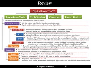
The pathway that carries the information from sender to receiver
Transmission Media
Guided “Cables”
Unguided
Copper
Fiber-optic
Radio
Microwave
Infrared
It is also referred to as Wired or Bounded transmission media.
Signals are directed in a narrow pathway by using physical links.
It is also referred to as Wireless or Unbounded transmission media.
No physical medium is required for the transmission of electromagnetic signals.
Twisted-Pair It consists of 2 separately insulated conductor wires wound about each other.
Generally, several such pairs are bundled together in a protective sheath.
UTP
STP
Typically wrapped inside a plastic cover (for mechanical protection).
This type of cable has the ability to block interference (used for telephonic applications).
Similar to UTP cables, except it has special jacket that cover each pair of insulated wires used to block
external interference (used in fast-data-rate Ethernet and in voice and data channels of telephone lines.
It has an outer plastic covering containing 2 parallel conductors each having a separate insulated
protection cover. It carry signals of higher frequency than UTP cables (used for Cable TVs).
It consists of a core (denser material) surrounded by a cladding (less dense material). It uses the concept of
reflection of light through a core made up of glass or plastic (used for transmission of large volumes of data).
Frequencies in the range of 30 MHz to 1 GHz (used for omnidirectional applications).
Frequencies in the range of 1 GHz to 40 GHz (used for satellite communications).
Frequencies in the range of 3 to 2 Hz.
Infrared is useful to local point-to-point and multipoint applications within confined areas, such as a single room.
Cards Standard Connectors Layer 1 Devices
Physical Layer “LAN”
5.
Data Link layer
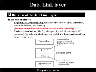
Divisions of the Data Link Layer
Computer Networks
It has two sublayers:
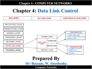
1. Logical Link Control (LLC): It handles error detection & correction,
data flow control, and framing.
(Ensures communication between devices works smoothly).
2. Media Access Control (MAC): Manages physical addressing (MAC
addresses).Controls how devices access and share the network medium
(wired or wireless).
6.
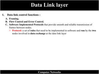
1. Data linkcontrol functions :
Data Link layer
Computer Networks
A. Framing.
B. Flow Control and Error Control.
C. Software Implemented Protocols that provide smooth and reliable transmission of
frames between nodes.
o Protocol: a set of rules that need to be implemented in software and run by the two
nodes involved in data exchange at the data link layer
7.
Data transmissionin the physical layer means moving bits in the form of a
signal from the source to the destination.
The physical layer provides bit synchronization to ensure that the sender and
receiver use the same bit durations and timing.
Data Link layer
Computer Networks
8.
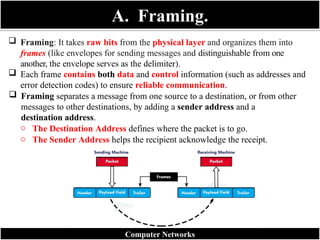
A. Framing.
Framing:It takes raw bits from the physical layer and organizes them into
frames (like envelopes for sending messages and distinguishable from one
another, the envelope serves as the delimiter).
Each frame contains both data and control information (such as addresses and
error detection codes) to ensure reliable communication.
Framing separates a message from one source to a destination, or from other
messages to other destinations, by adding a sender address and a
destination address.
o The Destination Address defines where the packet is to go.
o The Sender Address helps the recipient acknowledge the receipt.
Computer Networks
9.
A. Framing (Cont.)
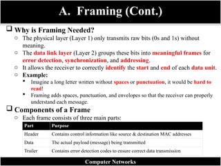
Why is Framing Needed?
o The physical layer (Layer 1) only transmits raw bits (0s and 1s) without
meaning.
o The data link layer (Layer 2) groups these bits into meaningful frames for
error detection, synchronization, and addressing.
o It allows the receiver to correctly identify the start and end of each data unit.
o Example:
Imagine a long letter written without spaces or punctuation, it would be hard to
read!
Framing adds spaces, punctuation, and envelopes so that the receiver can properly
understand each message.
Components of a Frame
o Each frame consists of three main parts:
Computer Networks
Part Purpose
Header Contains control information like source & destination MAC addresses
Data The actual payload (message) being transmitted
Trailer Contains error detection codes to ensure correct data transmission
10.
Types of Framing
ComputerNetworks
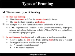
There are two types of Framing:
1. In fixed-size framing:
o There is no need to define the boundaries of the frames.
o The size itself can be used as a delimiter.
For example, ATM uses frames of fixed size called cells of 53 bytes.
o ATM: Asynchronous Transfer Mode (connection-oriented, high-speed
network technology that is used in both LAN and WAN over optical fiber
and operates upto gigabit speed.
2. In variable-size framing (which is widespread in local area networks)
o A way to define the end of the frame and the start of the next is required.
o Two approaches were used for this purpose:
A. A character-oriented approach
B. A bit-oriented approach.
11.
Character-Oriented Protocols
Computer Networks
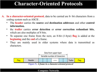
A.In a character-oriented protocol, data to be carried are 8- bit characters from a
coding system such as ASCII .
• The header carries the source and destination addresses and other control
information.
• the trailer carries error detection or error correction redundant bits,
which are also multiples of 8 bits.
• To separate one frame from the next, an 8-bit (1-byte) flag is added at the
beginning and the end of a frame.
• They are mainly used in older systems where data is transmitted as
characters.
Figure X. A frame in a character-oriented protocol
12.
Control
Symbol
Full Name
ASCII
Code (Hex)
Function
DLEData Link Escape 10 Indicates that the next character is a control character (not data).
STX Start of Text 02 Marks the beginning of the data field within a frame.
ETX End of Text 03 Marks the end of the data field within a frame.
Main Control Characters (Flags)
Character-Oriented Protocols
Computer Networks
How They Work Together
o A typical frame in a character-oriented protocol is structured like this:
[DLE STX] Header + Data [DLE ETX] Error Check (CRC)
o The combination DLE STX tells the receiver:
“The actual data begins here.”
👉
o The combination DLE ETX tells the receiver:
“The data section ends here; what follows may be error-checking bits.”
👉
13.
Bit-Oriented Protocols
Computer Networks
B.In a bit-oriented protocol, the data section of a frame is a sequence of bits to be
interpreted by the upper layer as text, images, audio, video, and so on.
o A specific 8-bit pattern flag (01111110) is used as the delimiter to define the
start and the end of the frame.
o Modern systems use bit-oriented framing (e.g. HDLC, PPP).
o This approach is more efficient and flexible for multimedia data.
Example:
01111110 [Header + Data + Trailer] 01111110
Figure x. A frame in a bit-oriented protocol
14.
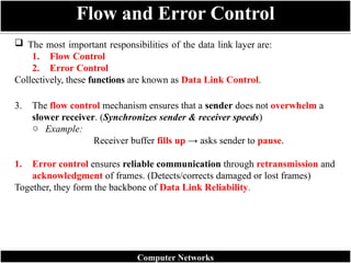
The mostimportant responsibilities of the data link layer are:
1. Flow Control
2. Error Control
Collectively, these functions are known as Data Link Control.
3. The flow control mechanism ensures that a sender does not overwhelm a
slower receiver. (Synchronizes sender & receiver speeds)
o Example:
Receiver buffer fills up → asks sender to pause.
1. Error control ensures reliable communication through retransmission and
acknowledgment of frames. (Detects/corrects damaged or lost frames)
Together, they form the backbone of Data Link Reliability.
Flow and Error Control
Computer Networks
15.
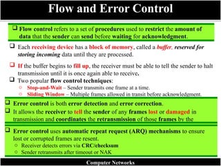
Flow controlrefers to a set of procedures used to restrict the amount of
data that the sender can send before waiting for acknowledgment.
Each receiving device has a block of memory, called a buffer, reserved for
storing incoming data until they are processed.
If the buffer begins to fill up, the receiver must be able to tell the sender to halt
transmission until it is once again able to receive.
Two popular flow control techniques:
o Stop-and-Wait – Sender transmits one frame at a time.
o Sliding Window – Multiple frames allowed in transit before acknowledgment.
Flow and Error Control
Error control is both error detection and error correction.
It allows the receiver to tell the sender of any frames lost or damaged in
transmission and coordinates the retransmission of those frames by the
sender.
Error control uses automatic repeat request (ARQ) mechanisms to ensure
lost or corrupted frames are resent.
o Receiver detects errors via CRC/checksum
o Sender retransmits after timeout or NAK
Computer Networks
16.
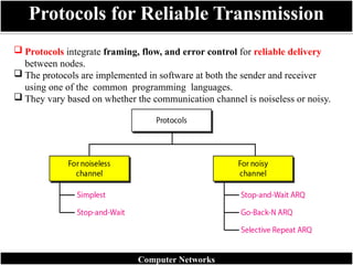
Protocols integrateframing, flow, and error control for reliable delivery
between nodes.
The protocols are implemented in software at both the sender and receiver
using one of the common programming languages.
They vary based on whether the communication channel is noiseless or noisy.
Protocols for Reliable Transmission
Computer Networks
17.
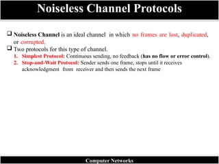
Noiseless Channelis an ideal channel in which no frames are lost, duplicated,
or corrupted.
Two protocols for this type of channel.
1. Simplest Protocol: Continuous sending, no feedback (has no flow or error control).
2. Stop-and-Wait Protocol: Sender sends one frame, stops until it receives
acknowledgment from receiver and then sends the next frame
Noiseless Channel Protocols
Computer Networks
18.
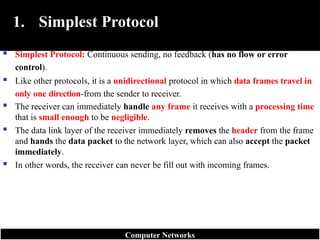
1. Simplest Protocol
Simplest Protocol: Continuous sending, no feedback (has no flow or error
control).
Like other protocols, it is a unidirectional protocol in which data frames travel in
only one direction-from the sender to receiver.
The receiver can immediately handle any frame it receives with a processing time
that is small enough to be negligible.
The data link layer of the receiver immediately removes the header from the frame
and hands the data packet to the network layer, which can also accept the packet
immediately.
In other words, the receiver can never be fill out with incoming frames.
Computer Networks
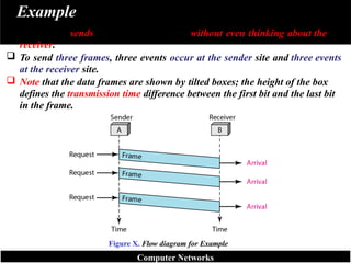
Example
The sendersends a sequence of frames without even thinking about the
receiver.
To send three frames, three events occur at the sender site and three events
at the receiver site.
Note that the data frames are shown by tilted boxes; the height of the box
defines the transmission time difference between the first bit and the last bit
in the frame.
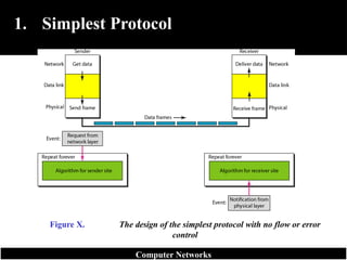
Figure X. Flow diagram for Example
Computer Networks
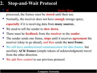
22.
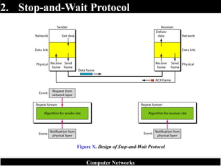
2. Stop-and-Wait Protocol
If data frames arrive at the receiver site faster than they can be
processed, the frames must be stored until their use.
Normally, the receiver does not have enough storage space,
especially if it is receiving data from many sources.
We need to tell the sender to slow down.
There must be feedback from the receiver to the sender.
The sender sends one frame, stops until it receives agreement the
receiver (okay to go ahead), and then sends the next frame.
We still have unidirectional communication for data frames, but
auxiliary ACK frames (simple tokens of acknowledgment) travel
from the other direction.
We add flow control to our previous protocol.
Computer Networks
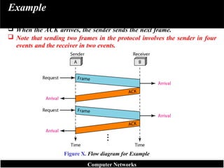
Example
The sendersends one frame and waits for feedback from the receiver.
When the ACK arrives, the sender sends the next frame.
Note that sending two frames in the protocol involves the sender in four
events and the receiver in two events.
Figure X. Flow diagram for Example
Computer Networks
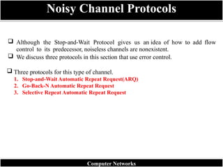
25.
Although theStop-and-Wait Protocol gives us an idea of how to add flow
control to its predecessor, noiseless channels are nonexistent.
We discuss three protocols in this section that use error control.
Three protocols for this type of channel.
1. Stop-and-Wait Automatic Repeat Request(ARQ)
2. Go-Back-N Automatic Repeat Request
3. Selective Repeat Automatic Repeat Request
Noisy Channel Protocols
Computer Networks
26.
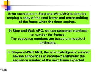
Error correction inStop-and-Wait ARQ is done by
keeping a copy of the sent frame and retransmitting
of the frame when the timer expires.
11.26
In Stop-and-Wait ARQ, we use sequence numbers
to number the frames.
The sequence numbers are based on modulo-2
arithmetic.
In Stop-and-Wait ARQ, the acknowledgment number
always announces in modulo-2 arithmetic the
sequence number of the next frame expected.
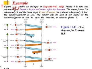
Figure 11.11 showsan example of Stop-and-Wait ARQ. Frame 0 is sent and
acknowledged. Frame 1 is lost and resent after the time-out. The resent frame 1 is
acknowledged and the timer stops. Frame 0(second ) is sent and acknowledged, but
acknowledgment is lost, so after the time-out, it resends frame 0,
which
the acknowledgment is lost. The sender has no idea if the frame or the
is
acknowledged.
Example
11.3
Figure 11.11 Flow
diagram for Example
11.3
1
29.
11.29
Pipelining
In networkingand in other areas, a task is often begun
before the previous task has ended. This is known as
pipelining. There is no pipelining in Stop-and-Wait ARQ
because we need to wait for a frame to reach the
destination and be acknowledged before the next frame
can be sent.
Pipelining improves the efficiency of the transmission if
the number of bits in transition is large with respect to
the bandwidth-delay .
30.
11.30
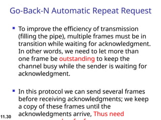
Go-Back-N Automatic RepeatRequest
To improve the efficiency of transmission
(filling the pipe), multiple frames must be in
transition while waiting for acknowledgment.
In other words, we need to let more than
one frame be outstanding to keep the
channel busy while the sender is waiting for
acknowledgment.
In this protocol we can send several frames
before receiving acknowledgments; we keep
a copy of these frames until the
acknowledgments arrive, Thus need
31.
In the Go-Back-NProtocol, the sequence
numbers are modulo 2m,
where m is the size of the sequence
number field in bits.
For example, if m is 4, the only sequence
numbers are 0 through 15 inclusive.
However, we can repeat the sequence.
Note
11.31
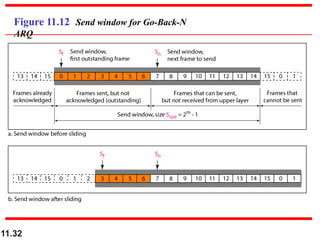
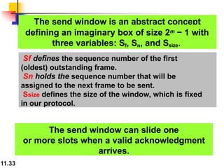
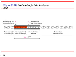
The send windowis an abstract concept
11.33
defining an imaginary box of size 2m − 1 with
three variables: Sf, Sn, and Ssize.
The send window can slide one
or more slots when a valid acknowledgment
arrives.
Sf defines the sequence number of the first
(oldest) outstanding frame.
Sn holds the sequence number that will be
assigned to the next frame to be sent.
Ssize defines the size of the window, which is fixed
in our protocol.
34.
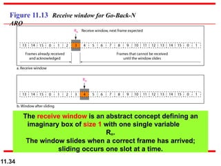
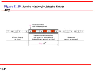
Figure 11.13 Receivewindow for Go-Back-N
ARQ
The receive window is an abstract concept defining an
imaginary box of size 1 with one single variable
Rn.
The window slides when a correct frame has arrived;
sliding occurs one slot at a time.
11.34
11.36
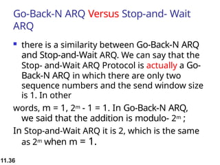
Go-Back-N ARQ VersusStop-and- Wait
ARQ
there is a similarity between Go-Back-N ARQ
and Stop-and-Wait ARQ. We can say that the
Stop- and-Wait ARQ Protocol is actually a Go-
Back-N ARQ in which there are only two
sequence numbers and the send window size
is 1. In other
words, m = 1, 2m - 1 = 1. In Go-Back-N ARQ,
we said that the addition is modulo- 2m ;
In Stop-and-Wait ARQ it is 2, which is the same
as 2m when m = 1.
37.
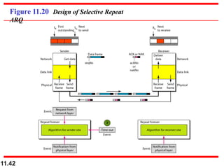
11.37
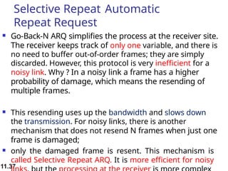
Selective Repeat Automatic
RepeatRequest
Go-Back-N ARQ simplifies the process at the receiver site.
The receiver keeps track of only one variable, and there is
no need to buffer out-of-order frames; they are simply
discarded. However, this protocol is very inefficient for a
noisy link. Why ? In a noisy link a frame has a higher
probability of damage, which means the resending of
multiple frames.
This resending uses up the bandwidth and slows down
the transmission. For noisy links, there is another
mechanism that does not resend N frames when just one
frame is damaged;
only the damaged frame is resent. This mechanism is
called Selective Repeat ARQ. It is more efficient for noisy
38.
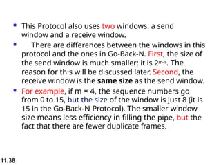
11.38
This Protocolalso uses two windows: a send
window and a receive window.
There are differences between the windows in this
protocol and the ones in Go-Back-N. First, the size of
the send window is much smaller; it is 2m-1. The
reason for this will be discussed later. Second, the
receive window is the same size as the send window.
For example, if m = 4, the sequence numbers go
from 0 to 15, but the size of the window is just 8 (it is
15 in the Go-Back-N Protocol). The smaller window
size means less efficiency in filling the pipe, but the
fact that there are fewer duplicate frames.
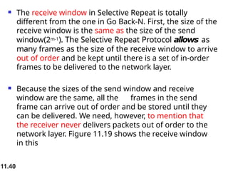
11.40
The receivewindow in Selective Repeat is totally
different from the one in Go Back-N. First, the size of the
receive window is the same as the size of the send
window(2m-1). The Selective Repeat Protocol allows as
many frames as the size of the receive window to arrive
out of order and be kept until there is a set of in-order
frames to be delivered to the network layer.
Because the sizes of the send window and receive
window are the same, all the frames in the send
frame can arrive out of order and be stored until they
can be delivered. We need, however, to mention that
the receiver never delivers packets out of order to the
network layer. Figure 11.19 shows the receive window
in this
In Selective RepeatARQ, the size of the
sender and receiver window
must be at most one-half of 2m.
Note
11.43
44.
11.44
Piggybacking
The threeprotocols we discussed in this section are all
unidirectional: data frames flow in only one direction although
control information such as ACK and NAK frames can travel in
the other direction. In real life, data frames are normally
flowing in both directions: from node A to node B and from
node B to node A. This means that the control information also
needs to flow in both directions.
A technique called piggybacking is used to improve the
efficiency of the bidirectional protocols. When a frame is
carrying data from A to B, it can also carry control information
about arrived (or lost) frames from B; and verse versa.
45.
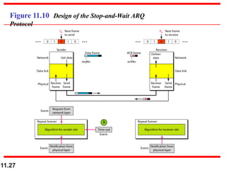
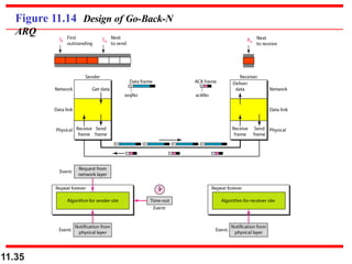
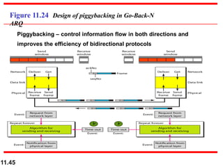
Figure 11.24 Designof piggybacking in Go-Back-N
ARQ
Piggybacking – control information flow in both directions and
improves the efficiency of bidirectional protocols
11.45
46.
Note thateach node now has two windows: one send
window and one receive window. Both also need to
use a timer.
An important point about piggybacking is that
both sites must use the same algorithm.
This algorithm is complicated because it needs to
combine two arrival events into one.
11.46
47.
HDLC
High-level Data LinkControl (HDLC) is a bit-oriented protocol for
communication over point-to-point and multipoint links. It
implements the ARQ mechanisms .
HDLC provides two common transfer modes that can be used
in different configurations: normal response mode (NRM) and
asynchronous balanced mode (ABM).
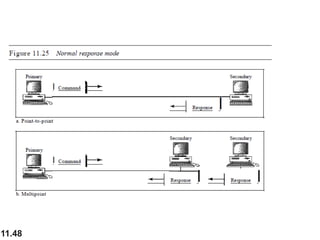
In normal response mode (NRM), the station configuration is
unbalanced. We h:ave one primary station and multiple secondary
stations. A primary station can send commands; a secondary
station can only respond. The NRM is used for both point-to-point
and multiple-point links, as shown in Figure 11.25.
11.47
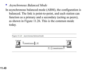
Asynchronous BalancedMode
In asynchronous balanced mode (ABM), the configuration is
balanced. The link is point-to-point, and each station can
function as a primary and a secondary (acting as peers),
as shown in Figure 11.26. This is the common mode
today.
11.49

![Control
Symbol
Full Name
ASCII
Code (Hex)
Function
DLE Data Link Escape 10 Indicates that the next character is a control character (not data).
STX Start of Text 02 Marks the beginning of the data field within a frame.
ETX End of Text 03 Marks the end of the data field within a frame.
Main Control Characters (Flags)
Character-Oriented Protocols
Computer Networks
How They Work Together
o A typical frame in a character-oriented protocol is structured like this:
[DLE STX] Header + Data [DLE ETX] Error Check (CRC)
o The combination DLE STX tells the receiver:
“The actual data begins here.”
👉
o The combination DLE ETX tells the receiver:
“The data section ends here; what follows may be error-checking bits.”
👉](https://image.slidesharecdn.com/session6-260125131654-2ec25eca/85/Computer-Networking-and-Data-Communication-Data-Link-Layer-12-320.jpg)
![Bit-Oriented Protocols
Computer Networks
B. In a bit-oriented protocol, the data section of a frame is a sequence of bits to be
interpreted by the upper layer as text, images, audio, video, and so on.
o A specific 8-bit pattern flag (01111110) is used as the delimiter to define the
start and the end of the frame.
o Modern systems use bit-oriented framing (e.g. HDLC, PPP).
o This approach is more efficient and flexible for multimedia data.
Example:
01111110 [Header + Data + Trailer] 01111110
Figure x. A frame in a bit-oriented protocol](https://image.slidesharecdn.com/session6-260125131654-2ec25eca/85/Computer-Networking-and-Data-Communication-Data-Link-Layer-13-320.jpg)