SlideShare a Scribd company logo
92 Lott Creek Landing SW  Calgary  AB  T3Z 3V4
Tel: (403) 608-5577  E-mail: tomols@shaw.ca
Page 2 of 41
Table of contents
LETTER OF INTRODUCTION .................................................................. 3
MEET THE D3 TEAM ............................................................................. 4
D3 PLOTTING CAPABILITIES................................................................. 6
SOURCING OUT TO D3 TECH VS HIRING ................................................. 7
THE 3D ADVANTAGE.......................................................................... 13
RAPID PROTOTYPING ........................................................................ 15
WHAT IS RAPID PROTOTYPING? ................................................................ 15
GIS APPLICATION ................................................................................ 17
PROTOTYPING STAGES ILLUSTRATED.......................................................... 22
D3 TECH’S PROJECTS....................................................................... 28
CLIENT: GEOLYN CONSULTANTS LTD. ..................................................... 29
CLIENT: LOCKERBIE & HOLE ................................................................ 31
CLIENT: COMSTOCK ........................................................................... 33
CLIENT: DCM MECHANICAL ................................................................. 34
CLIENT: AQUA EXTREMES INC................................................................ 35
CLIENT: PETROSTAR CORPORATION ........................................................ 36
CLIENT: BIRD CONSTRUCTION GENERAL CONTRACTORS ............................... 37
CLIENT: COOLIT SYSTEMS INC.............................................................. 38
CLIENT: WESTWAYS GROUP .................................................................. 40
CLIENT: ACS ENGINEERING ................................................................. 41
Page 3 of 41
LETTER OF INTRODUCTION
Thank you for the opportunity to introduce our company to you. D3
Technologies Inc. is a multidiscipline design and drafting company
specializing in Manufacturing, conceptual design, piping, structural &
mechanical designs. We provide to our clients a complete design &
fabrication solution that utilizes the latest software and equipment in
3D modeling technology world. We use CadWorx Plant Professional,
Inventor Professional and SolidWorks to create computer models that
can take physical shape through a 3D printing process we employ for
rapid prototyping. These models then can be put into service for concept
modeling, finite element analysis, functional testing, metal casting and
marketing (presentation models).
We have close ties to a number of small to mid-size fabrication facilities
throughout the province of alberta that have given us priorities on some
projects due to our long-term relationships and ongoing business. As an
additional service, we can micromanage projects for our clients to
ensure quality and of the meeting of schedules.
Enclosed, for your review, is our company profile. Thank you for your
time, and, if you have any questions, please give us a call and we would
love to meet with you and discuss the ways we can help your business.
Thank you,
Bill Tomol
President
Page 4 of 41
MEET THE D3 TEAM
Name Position Discipline Other
August, 2015
Bill Tomol Design Manager Multiple Shop/Field Exp.
Bill Smith Site Supervisor Multiple Shop/Field Exp.
Ben Gambles Fabrication Consultant Multiple Shop/Field Exp.
Richard LaPointe Machinist/Fabricator Multiple Shop/Field Exp.
Milena Tomol Office Manager Piping/Mech. Shop/Field Exp.
Grant Kitzul Checker/Designer Piping/Mech. Shop/Field Exp.
Al Kormos Designer Piping/Mech. Shop/Field Exp.
Dawn Leaman Designer Structural/Mech. Shop/Field Exp.
Josh Ludvigson Designer Piping/Struct. Shop/Field Exp.
Myles Nemenchek Designer Piping/Mech. Shop/Field Exp.
Greg Sakundiak Mechanical Engineer Piping/Mech. Shop/Field Exp.
Jack Jorgensen Mechanical Engineer Piping/Mech. Shop/Field Exp.
Page 5 of 41
D3 TECH’S TRACK RECORD
Design*:
 5-10 complex Iso drawings complete / day – intermediate (CADWORX)
Per Designer
 10-13 complex iso drawings / day –Senior (CADWORX) Per Designer
 FTP site upload direct to client instantly
Assuming title block, general notes, are setup properly.
Model making:
 Up to 7 jobs can be completed in one week
 Infinite variations and generations
 Models can be scaled to nearly any size
 Sizes up to 112” x 80” extrusions from 2D maps into 3D physical
Map
 Models can exhibit the look and finish of a variety of material
properties
Capacities:
 Assignments can go from 1 to 15 team members
 Can be assortment of intermediate to senior skills
 Capable of handling over 5 simultaneous projects at Project Value
Capacity: in the range of $5-6Million each project (oil & gas)
* these are based on estimates on the work of complex scenarios, actual estimates may vary.
Page 6 of 41
D3 PLOTTING CAPABILITIES
ANSI US Engineering:
Designation Dimensions (Metric) Dimensions (Imperial)
ANSI A 215.9 mm x 279.4 mm 8.5" x 11"
ANSI B 279.4 mm x 431.8 mm 11" x 17"
ANSI C 431.8 mm x 558.8 mm 17" x 22"
ANSI D 558.8 mm x 863.6 mm 22" x 34"
ANSI E 863.6 mm x 1117.6 mm 34" x 44"
ISO
Designation Dimensions (Metric)
A0 841 mm x 1189 mm
A1 594 mm x 841 mm
A2 420 mm x 594 mm
A3 297 mm x 420 mm
A4 210 mm x 297 mm
A5 149 mm x 210 mm
Paper Types available
Bright white injet paper
translucent bond
Natural tracing paper
vellum clear film, matte film
coated paper
heavyweight coated paper
high-gloss photo paper
semi-gloss photo paper
Paper based semi-gloss
satin poster paper
studio canvas
banners with Tyvek
colorfast adhesive vinyl
D3 drawing submittal methods:
FTP transfer site direct to client
Client login site
Electronic: pdf, dxf, idw and other formats available.
Page 7 of 41
SOURCING OUT TO D3 TECH vs HIRING
“Shall we outsource or handle it in-house?” - This is a common dilemma
for businesses faced with a problem that cannot be solved utilizing
current resources and core competences of the business. There is no
simple answer to this question, no “one-fits-all” solution. If you are
facing this dilemma right now, your decision will depend on the
resources, capital and time available to you. We cannot make this
decision for you, but we have put some information together that, we are
hoping, will help you make the right choice.
Outsourcing to D3 Technologies can help you reduce labor costs. Hiring
and training staff for short-term and/or peripheral projects can weigh
heavily on financial and human resources of your company. Besides,
temporary employees don’t always live up to your expectations and may
seek job opportunities elsewhere as soon as their training is complete.
D3 Technologies, on the other hand, is dedicated to fulfilling your
needs and building solid working relationships. Besides, outsourcing to
D3 Technologies will allow you to focus your human resources where
you need them most – your core business.
Outsourcing can reduce the need to invest capital funds in computer
equipment and software and release the funds for development of your
core competencies. The cost of acquiring workstations, design software
and keeping up with the latest software releases can run into tens of
thousands of dollars. These large expenditures can be easily avoided by
using D3 Technologies’ services on “as needed” basis. Using our services
will give you access to advanced technologies, state of the art
equipment and latest 3D software, as well as a large pool of creative
talent and higher level of expertise that you might have available in-
house – all at a fraction of the cost that you might incur by handling the
project internally.
Outsourcing can help you to start new projects quickly. It might take
weeks and months for a company to find the right people, train them and
provide the right tools for them to start the project. Having to
purchase computers and/or software, devise strategies and procedures
might delay the project startup even more. In contrast, D3 Technologies
has all the necessary resources ready to be deployed right away.
Furthermore, running a business carries a certain amount of risk.
Government regulations, markets, competition, financial conditions and
technologies can change very quickly. Keeping up with these changes is a
risky business. By assuming the design risks, D3 Technologies takes a
portion of this burden of your shoulders.
Page 8 of 41
Cost comparison
hiring full-time employees vs. sub-contracting with D3 Technologies
Full Time Employees Sub-contracting to D3
Technologies
$60,000.00 ~
$180,000.00 / year & per
employee
(based on $28-88/hr +
company overhead costs)
$115/hr based on project
(fixed cost)
(Depending on skill sets
And market demand)
You incur the cost of:
 Benefits
 monthly salary
 insurance costs
Eliminate payroll Expenses
You incur the cost of
 purchasing Computers
 design software and
subscriptions
 personnel training
gives you access to advanced
technologies, state of the
art equipment and latest
multiplatform software on
“as needed” basis
Possible high staff
turnover
D3 Tech is dedicated to
earning your business the
right way and developing a
long-term relationship.
Putting together a project
team can take weeks or
months
D3 Tech is ready to be
deployed immediately
Your company assumes all
the risks
D3 assumes design risks
staff members without
experience with each other
can cause project
bottlenecks especially if
members cannot cooperate
D3 Team members have long-
term experience in team
environment with each other.
This means no upsets and no
delays
If a firm is dependant on
project funding; you will
we can serve you where you
need us; during times of
Page 9 of 41
have to maintain a
consistent stream of income
in order to pay their
salaries; loss of funding
and sources may force
layoffs and paying out
severance packages.
heavy workloads or where a
competitive bid requires
expediting to win the
contract over the
competition.
Professional Design Software utilized
o Inventor Professional 2.0 thru 2012
o Solidworks 2005, 2006, 2010
o Rebis Plantworks
o Pro-Steel
o Cadworx Professional 2006 thru 2011
o AutoCad 2000 to 2011
Existing Alliances with specialty Fabricators in Alberta
o WestFab Industries Ltd. (Calgary)
o Westways Group (Edmonton)
o Benco Inc. (Calgary)
o Almac Machine Works Ltd. (Edmonton)
o Millway industries Inc. (Calgary)
o Lapointe Industrial (Calgary)
o HVC CANADA (EDMONTON)
o Lockerbie Hole (Calgary & Edmonton)
o Startec Compression (Calgary)
Page 10 of 41
USING D3 TECH IGM & STAFFING AGENCY
IGM – Integrated Group Members
all designers and detailers at d3 Technologies work closely together
on projects. There are no “WHITE KNIGHTS” here and we share our
knowledge. This ultimately develops personality compatibilities and a
true “teamwork” environment. IGM is a permanent solution for
regular and or specialized projects
SGM – Standard Group Members
Designers are put together for a project. There is no guarantee the
members will remain in the team because members will come and go
based on opportunities that are presented to them. SGM is a
temporary solution for projects.
Scenario:
Client requires 8 new staff for several projects on hand.
In many cases, a technical staffing agency is the first place a company
may look. Going to technical staffing agencies significantly reduces the
risk of unreliable and inexperienced people to the end-client itself.
D3 Technologies would like to supply the igm unit to the staffing agency
Requirements:
Clients may require project members have actual team experience vs.
Individual experience in a team environment. (Actual team experience is a
group of designers completing many projects together.)
Obviously a team of people are going to perform significantly better than
a team of people which don’t really have project experience with each
other) standard group members (SGM)
Executing a project with SGM poses a number of risks:
Bringing a group of people together may not guarantee your client a
smooth project;
Some may have conflicts
Some are strangers to each other
Some are not going to get along with each other
Some even pursue new opportunities without notice
Lack of an established team process may cause delays in projects
If an individual has to be replaced by introducing a new one, the new one
needs time to “catch up” to the project.
Page 11 of 41
A disadvantage with having a SGM team is that funds will have to
allocate to sustain that group. If the project funds are gone, then the
dissemination of SGM occurs. Imagine trying to build an all-star design
team only to have it fragment due to lack of funding.
There are simply too many variables to guarantee a new team of people
will perform to the client’s expectations. Having that guarantee will put
your staffing company at the front of the industry.
Benefits
D3 technologies igm group provide its’ services in-house. Technical
Staffing Company can partner with d3 in the following way:
From the very beginning of the project you have qualified people
without question. Additionally, our team is able to handle more
than several projects simultaneously, enabling you to use the same
D3 igm team over and over again for different clients.
Profit multipliers for each individual is good, it is even better when
there is a group of people.
D3 Technologies has personnel of 8-12 intermediate and senior
level designers; providing experienced professionals from beginning
of project to the final completion. Result: consistency in delivery
of service (offers opportunities for repeat business)
Repeating business with the client helps us establish the process
(we both know exactly what the client requires) Result: Doing
business with the same client and same skills supplier (d3 IGM)
offers constant repeatability and flexibility.
A D3 technology has an established multi-disciplinary design
philosophy able to respond to mechanical, structural, industrial
and commercial industries. This Eliminates having to “search” for
individuals when D3 IGM group is already here. Result: This
removes an entire search process.
D3 Technologies Wants to partner up with your company by
providing profit opportunities and multi-disciplinary skills. Result:
Your choice of flat rate or hourly mark-up.
Reduce time to “search and match” several individuals without
guarantee compatibility. D3 Technologies IGM group can guarantee
because we have several individuals and several disciplines.
Result: One-stop shop to produce work.
Page 12 of 41
?
Advantages (d3 IGM vs. new team members)
D3 IGM Group: New Project Team Members:
Team members all know each other Not all members know each
other
All Disciplines covered Assorted Disciplines
Experienced Team (as whole) inexperienced team (as whole)
Fixed cost for projects Unfixed cost & overtime hours
Cooperative Team member’s possible member conflicts
Able to handle several projects Still Familiarizing with each
other on first and second
project
Page 13 of 41
THE 3D ADVANTAGE
D3 Technologies Inc. prides itself to be a leader in 3D computer
modeling technology. Our 3D CAD capabilities enable us to provide a
better quality service to our clients. For us, 3D model is not just a
pretty picture, but a catalyst for more creative and efficient design and
a powerful tool that helps us create a direct impact on the bottom line
and improve productivity. While benefits of 3D Cad are generally well
known, we find that they are not always well understood and/or
accepted. Well known or not, here is a brief summary of what they are:
1. 3D modeling provides expediency in eliminating errors.
Sets of 2D drawings are always subject to ambiguity and
misinterpretation: deriving information to feed downstream process
like purchasing, testing and manufacturing not only takes time, but
has a great potential for mistakes. This error potential is
eliminated in 3D modeling because, through visualization of
interferences and clashes between parts, mistakes are identified as
soon as they occur.
2. 3D modeling increases efficiency and drawing productivity: A set of
conventional 2D drawings can be produced from an accurate 3D
model virtually automatically with a touch of a button: simply drag
the 3D view data and move it into a 2D drawing with isometric views.
Voile! You’ve got a dimensioned fabrication drawing and its
accuracy is assured!
3. 3D modeling makes design changes fast and easy. "On the fly"
changes to a singular part or assembly can be made to immediately
determine the feasibility of the desired configuration. Once all the
mating conditions, constrains and relationships between the parts
are defined, a single Dimensional change can give "fluid" changes to
the 2D drawings without having to redraw or update a hundred of
drawings. A change to one part instantly updates the 2D aspects of
the rest of the model.
4. 3D Modeling creates parametric data that could be used for
downstream processes like:
 Finite Element Analysis
 Stress Testing Platform
 Rapid Prototyping
 CNC Machining
 Assembly animation
 Marketing Presentations at trade shows and or customer
sites.
Page 14 of 41
5. 3D modeling places at designer’s fingertips a powerful range of
commands (View slicing, cuts, rotations, geometric projections,
perspective angles, wire frame and transparency) that give full
understanding of a part or assembly during design process.
6. Modern 3D CAD systems are equipped with data management
capabilities that will automatically track revision status of
documents, maintain correct links between parts, assemblies and
drawings as the design evolves, manage change orders and maintain
the product structure so that bill of material and material take
offs are always complete and up-to-date.
7. 3D modeling is as much a communication tool as it is a design tool.
Any complex industrial project requires a number of people working
in collaboration. 3Dmodeling creates a single information source
that can be used concurrently by engineers, designers,
procurement specialists, general contractors, construction
managers, manufactures, marketers, customers, etc. One model
feeds the whole enterprise.
In conclusion, let us give you a little illustration: typical rework
associated with 2D design is 10%; for a $100,000.00 valued project,
the rework becomes $10,000.00. In contrast, rework for 3D parametric
modeling is seen as low as <0.5%, which translates in less than
$500.00 in rework for the same project, thus, giving you over
$9,000.00 in cost savings. So, what are you waiting for? Go 3D with D3!
Page 15 of 41
RAPID PROTOTYPING
What is Rapid Prototyping?
Simple process of additive layer printing creates complex 3D hand held
models
a thin layer of inert powder is spread across he build plate; this is
subsequently the first layer. Precision built gantry system "prints" each
cross-sectioned layer. The binder solution comes into contact with the
thin layer of powder; it then reacts to form a porous crystal structure.
The process is repeated until a full 3D part is completed. 3D part or
assembly data can be created into a hand held prototype in as less than
3 days (size dependant)
Finishing and Coloring
The layer based addition-printing techniques offer significant benefits in
terms of build speed. Our skilled team of finishers combines the
functionality of parts with high quality aesthetics, with minimal time
added to the delivery. Providing a range of finishing techniques from
simply adding a color or highlighting certain areas, to fully finished
marketing models, a finished prototype can play a vital role in
functionality testing, securing tender bids, design verification and
engineering studies.
Our model makers ensure that the full detail of every model matches
our high-quality standards; our models can be involved with many
machining processes (milling, drilled, tapped and lathed). In our
experience, a machining speed of 600-800 RPM produces the best results
painted with automotive finishes and exhibit a variety of material
properties.
Mould cavities can be created for a single-use non-ferrous metal
prototype. Eliminates tool and die setup. Prototype castings are
available, which is a formulated blend of plaster, sand and other
materials making casting of non-ferrous, low-temperature prototypes
possible.
Another material we provide is the D3 Elastomer type compound. This
material exhibits rubber-like characteristics and can be used for light
function testing as well.
Page 16 of 41
Standard Finishing Grades
Varying finishes can be achieved and we offer 4 standard grades, from a
light sanding over or a dusting of paint on identified surfaces, to the
majority of the layering removed from the external surfaces and paint
or a permanent surface coloring applied.
State I: Primary State
The first stage of prototype is extracted; the part is now porous,
however not ready for transportation or handling. To Finalize
prototype, drying, sanding and de-powdering is done to remove access
powder and generate a smoother part.
Material is heated (optional) and infiltrated with two-part liquid epoxy
(ZMAX) compound to reinforce part strength. Part’s strength is also
increased by approximately 700%; making it ready for light functioning
testing, transportation and model demonstration
State II: Prime and Paint
Following Post Processing is the prime and paint stage, offers aesthetic
model look enhancement.
State III: Advanced Stage Concept
Following prime, paint, comes clear coat, drill and tap, and or
electroplating process. This process gives a full finished advanced late
stage concept model for evaluation. Great tool for potential investors,
clients.
Other material finishes
D3 Technologies Cast Powder:
Mould cavities can be created for a single-use non-ferrous metal
prototype. Eliminates tool and die setup. Prototype castings are
available which is a formulated blend of plaster, sand and other
materials making casting of non-ferrous, low-temperature prototypes
possible.
Please Contact us to discuss your project in more detail.
For a quick quotation, please send a sample file to tomols@shaw.ca
(lowercase) Autocad *.dxf, *.stl, and *.wrl (vrml) file formats are the
formats required.
Page 17 of 41
GIS Application
The Problem:
Let’s say, your company is working on a full redesign of a commercial
building and it’s neighboring buildings. Sometimes even with many 2d
visuals, accurate 3D models may be necessary to communicate the layout
for the project and attain the contract. There are traditional methods
of cut and paste foam building which would take many months to
complete, not to mention the intricate details required to finish these
models.
The Solution:
Imagine… produce a rapid
model in full color
directly from CAD data
(Auto CAD DXF, VRML, STL
files) we would then
“Print” each layer at a time
until the entire model has
been formed.
Data as you see on the
screen can be directly
translated into the 3d
model; from topographical
images, population
densities, flow arrows,
zoning to scaled buildings
in true scaled sizes.
With different maps, producing different models of the same land area is
possible. It is only limited to how much information you want to place on
these models. These models can be fabricated into 24-bit color to
represent actual graphics.
A model such as a size of 8 ½ “ x 11“ x 2” can be produced in less than
96 hours, allowing for a fast turnaround time.
Page 18 of 41
Imagine The Result:
The possibility of being able to present highly complex build proposals
puts your company at the front end of the bid.
These models should be used as a powerful tool to fully explain the
concept and idea of the project. Additionally these models are simply
great for a marketing tool at trade shows, open houses, securing
potential investors and finalizing contracts.
Applications:
Sizing: Custom specification can be produced
Large: Large Models will require slicing for ease of transportation
and square matching at demonstration location. This is more
effective to have.
Page 19 of 41
Example: Below is a table of some of the sizes we can finish.
Available Model Sizes (Imperial Units)
Length Width
9 13
18 26
27 39
36 39
45 52
54 39
63 65
72 78
81 39
90 91
99 104
Please note: Sizes beyond 99” x 104” are special order.
Sizes smaller than 9” x 13” can be produced in less than 24
hours.
Page 20 of 41
Use: 3D extruded models can be used for military operations and
tactical planning,
Infrastructure and zone planning
Cartography information
Topological Data
GIS population densities, statistics
Landscape planning and development
Note: Large models may become quite difficult to transport, d3
Recommends slicing these models into “rectangular zones” so
that these pieces can be stored away into transportation
cases and then placed together at the demonstration
location. I.e. 42” x 30” can be sliced into say 9 sections
each being 13” x 9” in size.
Page 21 of 41
Statistics: maximum height: 7” (minimum 0.5” base thickness)
Recommend width: 9” (each zone)
Recommend length: 13” (each zone)
Page 22 of 41
Prototyping Stages Illustrated
Mechanical drawings
Stage I prototype
Page 23 of 41
Prototyping Stages Illustrated
Stage 4 Prototype
Page 24 of 41
Stages Illustrated
Concept Drawings
Page 25 of 41
Stages Illustrated
3D Parametric Drawings
Page 26 of 41
Stages Illustrated
3D Physical Model in primed state
Sample Rapid Model Making Quotation of the above model
To complete an estimate the following information is required:
 Dimensions of air intake model
X=9.217” Width
Y=5.209” Length
Z=7.087” Height
 Desired State Finish
State I
State II
State III
 Paint Options: Monochromatic electric spec orange
 Option: Electroplating (non)
Page 27 of 41
 Option: Quantity; one (1)
 Option: Rush Delivery
Expedited
24 Hours
Standard (3 Days)
Calculated statistics
 Total part volume: 31.08 cubic inches
 Total surface area: 152.58 cubic inches
Compare the d3 Prototype with cnc and casting methods to produce one
model of the air intake system from previous page.
D3 prototype:
$2,050.00 (feasibility, light function testing, aesthetics evaluation,
advanced stage appearance, multiple generations, sales and marketing
material, 24 hours to manufacture)
COMPARE TO:
Cnc machining 3 axis:
$3,990.00 (feasibility, function testing, aesthetics evaluation,
engineering testing, limited generations, sales and marketing material, 1-
7 days for manufacturing)
Investment Casting:
$68,000.00 (production run following post-testing, single generation,
production run to last 12-18 weeks)
Additional Information:
 Material to be recommended thickness of 1/8” for every square
inch of increased material strength; equivalent material to chalk
strengthened with 2-part epoxy. Part strength is ultimately
related to part geometry and thickness.
 Thicker models generally offer better strength and detail for
intricate part
 File formats should be in the following:
o Step ap 214 (*.stp) Solidworks 2005
o Vrml (*.wrl*) 24-Bit color
Page 28 of 41
D3 TECH’S PROJECTS
Page 29 of 41
Client: Geolyn Consultants Ltd.
Project: Development of Multiple Application Inspection Probe (MATT)
Problem: Customer required a concept design and physical model of an
industrial scale multiple-application inspection robot
Solution: communicated preliminary concept design and 2d sketch
drawings
Continued design and updates on development of matt-1 to
client; created 3D models
Page 30 of 41
Client: Geolyn Consultants Ltd. (continued from previous page)
Project: Development of Multiple Application Inspection Probe (MATT)
Final design completed allowing up to 10 technology modules
to be installed into unit
Produced 1:1 scale non-function model of production run prototype for
sales and marketing purposes.
Mechanical layout and design of matt-1 components and
assemblies completed on inventor professional 9.0
Mechanical design detailing and 3d parametric model files
allow for future detail changes eliminating 2d rework.
Mechanical 3D data will serve as a platform for robot design
changes, enhancements and upgrades; opening possibilities
for client to release concurrent generation robots.
5 & 7 deployment arm “matt” robots are in design stage
Page 31 of 41
Client: Lockerbie & Hole
Project: Calgary health region – south health campus – mechanical
rooms phase 1
Value: 260 million
Problem: client request isometric / fabrication drawings for 5th
level,
8th
level and 9th
level mechanicals with clash detection along
the 3d modeling process between all the other project
specific contractors. (civil-structural, hvac, current
mechanical room layout, electrical, equipment layout)
Solution: completed isometric drawings c/w g.a.’s or system iso’s
Bill of material
Design notes on clashes or interferences
All drawings completed to spec on cadworx plant
professional
3D parametric models where produced to allow changes to be
made without incurring any rework by simply generating 2d
fabrication drawings from existing 3d data
3d design data allowed for project to be expedited ahead
of schedule
Page 32 of 41
Client: Lockerbie & Hole
Project: University of Alberta – penthouse mechanical room
Value: $50 Million
Problem: client request isometric / fabrication drawings for HRIF / West
Lower mechanical room / West Penthouse. Clash detection and
interference checks were done between all project related
sub-contractor disciplines
Solution: completed isometric drawings
Bill of material
Design notes for all interferences found along with a cost
saving was produced
All drawings completed to spec on cadworx plant pro
3D parametric models where produced to allow changes to be
made without incurring any rework by simply generating 2d
fabrication drawings from existing 3d data
3d design data allowed for project to be expedited ahead of
schedule
Mechanical Room systems
hps High Pressure Steam
hws hot water supply lines
lps Low Pressure Steam
cwr cold water return
ghr glycol heat return
ghs glycol heat supply
Page 33 of 41
Client: Comstock
Project: Winnipeg (deacon reservoir) water treatment facility
Value: 40 million
Problem: client request isometric / fabrication drawings for all the
large bore diameter steel piping throughout the water
treatment facility. Clash detection and interference checks
were to be preformed throughout the 3d modeling process
solution: completed isometric drawings
Bill of material
Design notes for all interferences found along with a cost
saving was produced
All drawings completed to spec on cadworx plant pro
3D parametric models where produced to allow changes to be
made without incurring any rework by simply generating 2d
fabrication drawings from existing 3d data
3d design data allowed for
project to be expedited ahead of
schedule
Page 34 of 41
Client: DCM Mechanical
Projects: aspen landing shopping center / Cambrian executive place
Value: 8 million & 15 million respectively
Problem: client request isometric / fabrication drawings for all the
large bore diameter steel piping throughout the shopping
center and executive center mechanical rooms. Clash
detection and interference checks were to be preformed
throughout the 3d modeling process
Solution: completed isometric drawings
Bill of material
Design notes for all interferences found along with a cost
saving was produced
All drawings completed to spec on cadworx plant pro
3D parametric models where produced to allow changes to be
made without incurring any rework by simply generating 2d
fabrication drawings from existing 3d data
3d design data allowed for project to be expedited ahead of
schedule
Page 35 of 41
Client: Rotary Engine Technologies Incorporated
Value: Ongoing R&D and design development for manufacturing &
commercial use
Project: “Jet” - Board and Rotary Engines design for Marine
applications
Problem: client requires 3d Data model library to be created for engine
testing, enhanced fabrication and illustration of internals.
Solution: currently taking 2D paper drawings and moving the original
designs into full parametric 3D model:
Propeller and propeller housing
Rotary assembly, gears and housing
Intake manifold
Internal components
“Jet” board mounting assembly design
Design assistance and fabrication drawings for 24 variations
of rotary engines.
3D data can be used for engine port calculations, flow and
exhaust enhancements to optimize performance, durability,
stress testing and simulations.
3d parametric data allow test engineers to make quick
changes to model assembly and respond to upgrade design
parameters.
Current design (parent data) allow us to produce model
variations and alternatively potential military applications.
Progressive design of up to 24 variations of rotary engines
Page 36 of 41
Client: Petrostar Corporation
Project: Oil Devil (underground heater enhanced oil recovery)
Problem: Petrostar requires mechanical drawings to be produced in
parametric model to cut 2D fabrication costs.
Solution: D3 Technologies produced 3D Data model for fabrication and
slight variations
Client is using original 3D models to explain internals and
operation of the oil devil to potential investors
Page 37 of 41
Client: Bird Construction General Contractors
Project: Syncrude booster pump house building and booster pump skid
package
Problem: End Client wanted all fabrication drawings and complete
package rendered in 3d data.
Solution: produced master 3D skid package of Booster Pump house. 2D
fabrication drawings were cut with existing 3D file information
and properties
Inventor Professional 9.0 was the parametric design software
of choice
Produced the following:
 Bill of Materials
 3D parametric Data
 2D fabrication drawings
 Structural Detailing
Page 38 of 41
Client: CoolIT Systems Inc
Project: multiple cooling fan housing unit Prototype
Problem: end client wanted advanced stage models for applications
testing.
Solution: D3 technologies provided a rapid prototype model before
decision to make a production tool and die setup
Client submitted original design data, D3 Technologies
Produced first prototype.
Enabled client to do the following:
 Able to perform light functional Part testing (cooling
rates)
 Internal assembly mounting
 Final aesthetic painting
 Make simple changes to finalize the Pre-Production
stage model
Page 39 of 41
D3 Technologies enabled CoolIt Systems to discover early
design flaws and conduct testing; saving valuable time and
funds that otherwise would be consumed by tool and die
setup.
Page 40 of 41
Client: Westways group
Project: Shell Hydrocyclone Pilot Plant Minnovex Unit
Problem: end client requires data and drawing sets to be created in 3D
Solution: D3 technologies used inventor professional to create 3D
assembly drawings:
Client can use main assembly drawings to better understand
details of skid
3D Assembly drawings can produce 2d Fabrication drawings
Page 41 of 41
Client: ACS Engineering
Project: EG West Africa refinery pfd
Problem: Client wanted to meet schedule, sourced out D3 Technologies
for overflow
Solution: Quickly produced over 25 drawings.
AutoCAD 2006 was the design software of choice
Produced the following:
 Equipment line tags
 Feed surge drum
 Single stage desalter
 Crude charge heater
 Stripping steam lines
 Tower charge lines
 Desalt, feed lines

More Related Content

Similar to Company Profile-08-11-2016 R1

Squeeze Time and Money out of Production Using Design for Manufacturability
Squeeze Time and Money out of Production Using Design for ManufacturabilitySqueeze Time and Money out of Production Using Design for Manufacturability
Squeeze Time and Money out of Production Using Design for ManufacturabilitySOLIDWORKS
 
3D Systems White Paper 3D printer buyer guide
3D Systems White Paper 3D printer buyer guide3D Systems White Paper 3D printer buyer guide
3D Systems White Paper 3D printer buyer guideQuoc Tuan Duong, ing.
 
Additive Manufacturing Industry Summit 2016 Guide Dayton Ohio
Additive Manufacturing Industry Summit 2016 Guide Dayton OhioAdditive Manufacturing Industry Summit 2016 Guide Dayton Ohio
Additive Manufacturing Industry Summit 2016 Guide Dayton OhioCBCT Magazine
 
Table of Contents .docx
Table of Contents                                          .docxTable of Contents                                          .docx
Table of Contents .docxmattinsonjanel
 
Contract manufacturing & assembly for machine builders and OEMs
Contract manufacturing & assembly for machine builders and OEMsContract manufacturing & assembly for machine builders and OEMs
Contract manufacturing & assembly for machine builders and OEMsTony Hague
 
Dayton #3DPrinting Summit Brouchure
Dayton #3DPrinting Summit BrouchureDayton #3DPrinting Summit Brouchure
Dayton #3DPrinting Summit BrouchureCBCT Magazine
 
Black Box Consulting 2009 Brochure
Black Box Consulting 2009 BrochureBlack Box Consulting 2009 Brochure
Black Box Consulting 2009 Brochurepboxall
 
Whats New At Prism Engineering
Whats New At Prism EngineeringWhats New At Prism Engineering
Whats New At Prism Engineeringpiscana01
 
What's New at Prism Engineering, Inc.?
What's New at Prism Engineering, Inc.?What's New at Prism Engineering, Inc.?
What's New at Prism Engineering, Inc.?guest838f180
 
Katmanlı Üretim (Additive manufacturing) bilgi görseli
Katmanlı Üretim (Additive manufacturing) bilgi görseliKatmanlı Üretim (Additive manufacturing) bilgi görseli
Katmanlı Üretim (Additive manufacturing) bilgi görseliAdem Çelik
 
DAF Enterprises, LLC 2
DAF Enterprises, LLC 2DAF Enterprises, LLC 2
DAF Enterprises, LLC 2Dale Flanery
 
Manufacturing Brochure
Manufacturing BrochureManufacturing Brochure
Manufacturing BrochureEd Flanagan
 
PDS Offload Enginerring
PDS Offload EnginerringPDS Offload Enginerring
PDS Offload EnginerringPDS Tech Inc.
 
Onshore-offshore model pain points Whitepaper
Onshore-offshore model pain points WhitepaperOnshore-offshore model pain points Whitepaper
Onshore-offshore model pain points WhitepaperThe Digital Group
 

Similar to Company Profile-08-11-2016 R1 (20)

Squeeze Time and Money out of Production Using Design for Manufacturability
Squeeze Time and Money out of Production Using Design for ManufacturabilitySqueeze Time and Money out of Production Using Design for Manufacturability
Squeeze Time and Money out of Production Using Design for Manufacturability
 
3D Systems White Paper 3D printer buyer guide
3D Systems White Paper 3D printer buyer guide3D Systems White Paper 3D printer buyer guide
3D Systems White Paper 3D printer buyer guide
 
Additive Manufacturing Industry Summit 2016 Guide Dayton Ohio
Additive Manufacturing Industry Summit 2016 Guide Dayton OhioAdditive Manufacturing Industry Summit 2016 Guide Dayton Ohio
Additive Manufacturing Industry Summit 2016 Guide Dayton Ohio
 
Table of Contents .docx
Table of Contents                                          .docxTable of Contents                                          .docx
Table of Contents .docx
 
Contract manufacturing & assembly for machine builders and OEMs
Contract manufacturing & assembly for machine builders and OEMsContract manufacturing & assembly for machine builders and OEMs
Contract manufacturing & assembly for machine builders and OEMs
 
de_aerospace_15_web
de_aerospace_15_webde_aerospace_15_web
de_aerospace_15_web
 
Dayton #3DPrinting Summit Brouchure
Dayton #3DPrinting Summit BrouchureDayton #3DPrinting Summit Brouchure
Dayton #3DPrinting Summit Brouchure
 
#3DPAM Dayton 2016
 #3DPAM Dayton 2016 #3DPAM Dayton 2016
#3DPAM Dayton 2016
 
Black Box Consulting 2009 Brochure
Black Box Consulting 2009 BrochureBlack Box Consulting 2009 Brochure
Black Box Consulting 2009 Brochure
 
Whats New At Prism Engineering
Whats New At Prism EngineeringWhats New At Prism Engineering
Whats New At Prism Engineering
 
What's New at Prism Engineering, Inc.?
What's New at Prism Engineering, Inc.?What's New at Prism Engineering, Inc.?
What's New at Prism Engineering, Inc.?
 
Rapidfinal
RapidfinalRapidfinal
Rapidfinal
 
Katmanlı Üretim (Additive manufacturing) bilgi görseli
Katmanlı Üretim (Additive manufacturing) bilgi görseliKatmanlı Üretim (Additive manufacturing) bilgi görseli
Katmanlı Üretim (Additive manufacturing) bilgi görseli
 
RMS presentation vii
RMS presentation viiRMS presentation vii
RMS presentation vii
 
DAF Enterprises, LLC 2
DAF Enterprises, LLC 2DAF Enterprises, LLC 2
DAF Enterprises, LLC 2
 
CS Technology
CS TechnologyCS Technology
CS Technology
 
Manufacturing Brochure
Manufacturing BrochureManufacturing Brochure
Manufacturing Brochure
 
PDS Offload Enginerring
PDS Offload EnginerringPDS Offload Enginerring
PDS Offload Enginerring
 
Onshore-offshore model pain points Whitepaper
Onshore-offshore model pain points WhitepaperOnshore-offshore model pain points Whitepaper
Onshore-offshore model pain points Whitepaper
 
2009 Comrise
2009 Comrise2009 Comrise
2009 Comrise
 

Company Profile-08-11-2016 R1

  • 1. 92 Lott Creek Landing SW  Calgary  AB  T3Z 3V4 Tel: (403) 608-5577  E-mail: tomols@shaw.ca
  • 2. Page 2 of 41 Table of contents LETTER OF INTRODUCTION .................................................................. 3 MEET THE D3 TEAM ............................................................................. 4 D3 PLOTTING CAPABILITIES................................................................. 6 SOURCING OUT TO D3 TECH VS HIRING ................................................. 7 THE 3D ADVANTAGE.......................................................................... 13 RAPID PROTOTYPING ........................................................................ 15 WHAT IS RAPID PROTOTYPING? ................................................................ 15 GIS APPLICATION ................................................................................ 17 PROTOTYPING STAGES ILLUSTRATED.......................................................... 22 D3 TECH’S PROJECTS....................................................................... 28 CLIENT: GEOLYN CONSULTANTS LTD. ..................................................... 29 CLIENT: LOCKERBIE & HOLE ................................................................ 31 CLIENT: COMSTOCK ........................................................................... 33 CLIENT: DCM MECHANICAL ................................................................. 34 CLIENT: AQUA EXTREMES INC................................................................ 35 CLIENT: PETROSTAR CORPORATION ........................................................ 36 CLIENT: BIRD CONSTRUCTION GENERAL CONTRACTORS ............................... 37 CLIENT: COOLIT SYSTEMS INC.............................................................. 38 CLIENT: WESTWAYS GROUP .................................................................. 40 CLIENT: ACS ENGINEERING ................................................................. 41
  • 3. Page 3 of 41 LETTER OF INTRODUCTION Thank you for the opportunity to introduce our company to you. D3 Technologies Inc. is a multidiscipline design and drafting company specializing in Manufacturing, conceptual design, piping, structural & mechanical designs. We provide to our clients a complete design & fabrication solution that utilizes the latest software and equipment in 3D modeling technology world. We use CadWorx Plant Professional, Inventor Professional and SolidWorks to create computer models that can take physical shape through a 3D printing process we employ for rapid prototyping. These models then can be put into service for concept modeling, finite element analysis, functional testing, metal casting and marketing (presentation models). We have close ties to a number of small to mid-size fabrication facilities throughout the province of alberta that have given us priorities on some projects due to our long-term relationships and ongoing business. As an additional service, we can micromanage projects for our clients to ensure quality and of the meeting of schedules. Enclosed, for your review, is our company profile. Thank you for your time, and, if you have any questions, please give us a call and we would love to meet with you and discuss the ways we can help your business. Thank you, Bill Tomol President
  • 4. Page 4 of 41 MEET THE D3 TEAM Name Position Discipline Other August, 2015 Bill Tomol Design Manager Multiple Shop/Field Exp. Bill Smith Site Supervisor Multiple Shop/Field Exp. Ben Gambles Fabrication Consultant Multiple Shop/Field Exp. Richard LaPointe Machinist/Fabricator Multiple Shop/Field Exp. Milena Tomol Office Manager Piping/Mech. Shop/Field Exp. Grant Kitzul Checker/Designer Piping/Mech. Shop/Field Exp. Al Kormos Designer Piping/Mech. Shop/Field Exp. Dawn Leaman Designer Structural/Mech. Shop/Field Exp. Josh Ludvigson Designer Piping/Struct. Shop/Field Exp. Myles Nemenchek Designer Piping/Mech. Shop/Field Exp. Greg Sakundiak Mechanical Engineer Piping/Mech. Shop/Field Exp. Jack Jorgensen Mechanical Engineer Piping/Mech. Shop/Field Exp.
  • 5. Page 5 of 41 D3 TECH’S TRACK RECORD Design*:  5-10 complex Iso drawings complete / day – intermediate (CADWORX) Per Designer  10-13 complex iso drawings / day –Senior (CADWORX) Per Designer  FTP site upload direct to client instantly Assuming title block, general notes, are setup properly. Model making:  Up to 7 jobs can be completed in one week  Infinite variations and generations  Models can be scaled to nearly any size  Sizes up to 112” x 80” extrusions from 2D maps into 3D physical Map  Models can exhibit the look and finish of a variety of material properties Capacities:  Assignments can go from 1 to 15 team members  Can be assortment of intermediate to senior skills  Capable of handling over 5 simultaneous projects at Project Value Capacity: in the range of $5-6Million each project (oil & gas) * these are based on estimates on the work of complex scenarios, actual estimates may vary.
  • 6. Page 6 of 41 D3 PLOTTING CAPABILITIES ANSI US Engineering: Designation Dimensions (Metric) Dimensions (Imperial) ANSI A 215.9 mm x 279.4 mm 8.5" x 11" ANSI B 279.4 mm x 431.8 mm 11" x 17" ANSI C 431.8 mm x 558.8 mm 17" x 22" ANSI D 558.8 mm x 863.6 mm 22" x 34" ANSI E 863.6 mm x 1117.6 mm 34" x 44" ISO Designation Dimensions (Metric) A0 841 mm x 1189 mm A1 594 mm x 841 mm A2 420 mm x 594 mm A3 297 mm x 420 mm A4 210 mm x 297 mm A5 149 mm x 210 mm Paper Types available Bright white injet paper translucent bond Natural tracing paper vellum clear film, matte film coated paper heavyweight coated paper high-gloss photo paper semi-gloss photo paper Paper based semi-gloss satin poster paper studio canvas banners with Tyvek colorfast adhesive vinyl D3 drawing submittal methods: FTP transfer site direct to client Client login site Electronic: pdf, dxf, idw and other formats available.
  • 7. Page 7 of 41 SOURCING OUT TO D3 TECH vs HIRING “Shall we outsource or handle it in-house?” - This is a common dilemma for businesses faced with a problem that cannot be solved utilizing current resources and core competences of the business. There is no simple answer to this question, no “one-fits-all” solution. If you are facing this dilemma right now, your decision will depend on the resources, capital and time available to you. We cannot make this decision for you, but we have put some information together that, we are hoping, will help you make the right choice. Outsourcing to D3 Technologies can help you reduce labor costs. Hiring and training staff for short-term and/or peripheral projects can weigh heavily on financial and human resources of your company. Besides, temporary employees don’t always live up to your expectations and may seek job opportunities elsewhere as soon as their training is complete. D3 Technologies, on the other hand, is dedicated to fulfilling your needs and building solid working relationships. Besides, outsourcing to D3 Technologies will allow you to focus your human resources where you need them most – your core business. Outsourcing can reduce the need to invest capital funds in computer equipment and software and release the funds for development of your core competencies. The cost of acquiring workstations, design software and keeping up with the latest software releases can run into tens of thousands of dollars. These large expenditures can be easily avoided by using D3 Technologies’ services on “as needed” basis. Using our services will give you access to advanced technologies, state of the art equipment and latest 3D software, as well as a large pool of creative talent and higher level of expertise that you might have available in- house – all at a fraction of the cost that you might incur by handling the project internally. Outsourcing can help you to start new projects quickly. It might take weeks and months for a company to find the right people, train them and provide the right tools for them to start the project. Having to purchase computers and/or software, devise strategies and procedures might delay the project startup even more. In contrast, D3 Technologies has all the necessary resources ready to be deployed right away. Furthermore, running a business carries a certain amount of risk. Government regulations, markets, competition, financial conditions and technologies can change very quickly. Keeping up with these changes is a risky business. By assuming the design risks, D3 Technologies takes a portion of this burden of your shoulders.
  • 8. Page 8 of 41 Cost comparison hiring full-time employees vs. sub-contracting with D3 Technologies Full Time Employees Sub-contracting to D3 Technologies $60,000.00 ~ $180,000.00 / year & per employee (based on $28-88/hr + company overhead costs) $115/hr based on project (fixed cost) (Depending on skill sets And market demand) You incur the cost of:  Benefits  monthly salary  insurance costs Eliminate payroll Expenses You incur the cost of  purchasing Computers  design software and subscriptions  personnel training gives you access to advanced technologies, state of the art equipment and latest multiplatform software on “as needed” basis Possible high staff turnover D3 Tech is dedicated to earning your business the right way and developing a long-term relationship. Putting together a project team can take weeks or months D3 Tech is ready to be deployed immediately Your company assumes all the risks D3 assumes design risks staff members without experience with each other can cause project bottlenecks especially if members cannot cooperate D3 Team members have long- term experience in team environment with each other. This means no upsets and no delays If a firm is dependant on project funding; you will we can serve you where you need us; during times of
  • 9. Page 9 of 41 have to maintain a consistent stream of income in order to pay their salaries; loss of funding and sources may force layoffs and paying out severance packages. heavy workloads or where a competitive bid requires expediting to win the contract over the competition. Professional Design Software utilized o Inventor Professional 2.0 thru 2012 o Solidworks 2005, 2006, 2010 o Rebis Plantworks o Pro-Steel o Cadworx Professional 2006 thru 2011 o AutoCad 2000 to 2011 Existing Alliances with specialty Fabricators in Alberta o WestFab Industries Ltd. (Calgary) o Westways Group (Edmonton) o Benco Inc. (Calgary) o Almac Machine Works Ltd. (Edmonton) o Millway industries Inc. (Calgary) o Lapointe Industrial (Calgary) o HVC CANADA (EDMONTON) o Lockerbie Hole (Calgary & Edmonton) o Startec Compression (Calgary)
  • 10. Page 10 of 41 USING D3 TECH IGM & STAFFING AGENCY IGM – Integrated Group Members all designers and detailers at d3 Technologies work closely together on projects. There are no “WHITE KNIGHTS” here and we share our knowledge. This ultimately develops personality compatibilities and a true “teamwork” environment. IGM is a permanent solution for regular and or specialized projects SGM – Standard Group Members Designers are put together for a project. There is no guarantee the members will remain in the team because members will come and go based on opportunities that are presented to them. SGM is a temporary solution for projects. Scenario: Client requires 8 new staff for several projects on hand. In many cases, a technical staffing agency is the first place a company may look. Going to technical staffing agencies significantly reduces the risk of unreliable and inexperienced people to the end-client itself. D3 Technologies would like to supply the igm unit to the staffing agency Requirements: Clients may require project members have actual team experience vs. Individual experience in a team environment. (Actual team experience is a group of designers completing many projects together.) Obviously a team of people are going to perform significantly better than a team of people which don’t really have project experience with each other) standard group members (SGM) Executing a project with SGM poses a number of risks: Bringing a group of people together may not guarantee your client a smooth project; Some may have conflicts Some are strangers to each other Some are not going to get along with each other Some even pursue new opportunities without notice Lack of an established team process may cause delays in projects If an individual has to be replaced by introducing a new one, the new one needs time to “catch up” to the project.
  • 11. Page 11 of 41 A disadvantage with having a SGM team is that funds will have to allocate to sustain that group. If the project funds are gone, then the dissemination of SGM occurs. Imagine trying to build an all-star design team only to have it fragment due to lack of funding. There are simply too many variables to guarantee a new team of people will perform to the client’s expectations. Having that guarantee will put your staffing company at the front of the industry. Benefits D3 technologies igm group provide its’ services in-house. Technical Staffing Company can partner with d3 in the following way: From the very beginning of the project you have qualified people without question. Additionally, our team is able to handle more than several projects simultaneously, enabling you to use the same D3 igm team over and over again for different clients. Profit multipliers for each individual is good, it is even better when there is a group of people. D3 Technologies has personnel of 8-12 intermediate and senior level designers; providing experienced professionals from beginning of project to the final completion. Result: consistency in delivery of service (offers opportunities for repeat business) Repeating business with the client helps us establish the process (we both know exactly what the client requires) Result: Doing business with the same client and same skills supplier (d3 IGM) offers constant repeatability and flexibility. A D3 technology has an established multi-disciplinary design philosophy able to respond to mechanical, structural, industrial and commercial industries. This Eliminates having to “search” for individuals when D3 IGM group is already here. Result: This removes an entire search process. D3 Technologies Wants to partner up with your company by providing profit opportunities and multi-disciplinary skills. Result: Your choice of flat rate or hourly mark-up. Reduce time to “search and match” several individuals without guarantee compatibility. D3 Technologies IGM group can guarantee because we have several individuals and several disciplines. Result: One-stop shop to produce work.
  • 12. Page 12 of 41 ? Advantages (d3 IGM vs. new team members) D3 IGM Group: New Project Team Members: Team members all know each other Not all members know each other All Disciplines covered Assorted Disciplines Experienced Team (as whole) inexperienced team (as whole) Fixed cost for projects Unfixed cost & overtime hours Cooperative Team member’s possible member conflicts Able to handle several projects Still Familiarizing with each other on first and second project
  • 13. Page 13 of 41 THE 3D ADVANTAGE D3 Technologies Inc. prides itself to be a leader in 3D computer modeling technology. Our 3D CAD capabilities enable us to provide a better quality service to our clients. For us, 3D model is not just a pretty picture, but a catalyst for more creative and efficient design and a powerful tool that helps us create a direct impact on the bottom line and improve productivity. While benefits of 3D Cad are generally well known, we find that they are not always well understood and/or accepted. Well known or not, here is a brief summary of what they are: 1. 3D modeling provides expediency in eliminating errors. Sets of 2D drawings are always subject to ambiguity and misinterpretation: deriving information to feed downstream process like purchasing, testing and manufacturing not only takes time, but has a great potential for mistakes. This error potential is eliminated in 3D modeling because, through visualization of interferences and clashes between parts, mistakes are identified as soon as they occur. 2. 3D modeling increases efficiency and drawing productivity: A set of conventional 2D drawings can be produced from an accurate 3D model virtually automatically with a touch of a button: simply drag the 3D view data and move it into a 2D drawing with isometric views. Voile! You’ve got a dimensioned fabrication drawing and its accuracy is assured! 3. 3D modeling makes design changes fast and easy. "On the fly" changes to a singular part or assembly can be made to immediately determine the feasibility of the desired configuration. Once all the mating conditions, constrains and relationships between the parts are defined, a single Dimensional change can give "fluid" changes to the 2D drawings without having to redraw or update a hundred of drawings. A change to one part instantly updates the 2D aspects of the rest of the model. 4. 3D Modeling creates parametric data that could be used for downstream processes like:  Finite Element Analysis  Stress Testing Platform  Rapid Prototyping  CNC Machining  Assembly animation  Marketing Presentations at trade shows and or customer sites.
  • 14. Page 14 of 41 5. 3D modeling places at designer’s fingertips a powerful range of commands (View slicing, cuts, rotations, geometric projections, perspective angles, wire frame and transparency) that give full understanding of a part or assembly during design process. 6. Modern 3D CAD systems are equipped with data management capabilities that will automatically track revision status of documents, maintain correct links between parts, assemblies and drawings as the design evolves, manage change orders and maintain the product structure so that bill of material and material take offs are always complete and up-to-date. 7. 3D modeling is as much a communication tool as it is a design tool. Any complex industrial project requires a number of people working in collaboration. 3Dmodeling creates a single information source that can be used concurrently by engineers, designers, procurement specialists, general contractors, construction managers, manufactures, marketers, customers, etc. One model feeds the whole enterprise. In conclusion, let us give you a little illustration: typical rework associated with 2D design is 10%; for a $100,000.00 valued project, the rework becomes $10,000.00. In contrast, rework for 3D parametric modeling is seen as low as <0.5%, which translates in less than $500.00 in rework for the same project, thus, giving you over $9,000.00 in cost savings. So, what are you waiting for? Go 3D with D3!
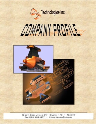
  • 15. Page 15 of 41 RAPID PROTOTYPING What is Rapid Prototyping? Simple process of additive layer printing creates complex 3D hand held models a thin layer of inert powder is spread across he build plate; this is subsequently the first layer. Precision built gantry system "prints" each cross-sectioned layer. The binder solution comes into contact with the thin layer of powder; it then reacts to form a porous crystal structure. The process is repeated until a full 3D part is completed. 3D part or assembly data can be created into a hand held prototype in as less than 3 days (size dependant) Finishing and Coloring The layer based addition-printing techniques offer significant benefits in terms of build speed. Our skilled team of finishers combines the functionality of parts with high quality aesthetics, with minimal time added to the delivery. Providing a range of finishing techniques from simply adding a color or highlighting certain areas, to fully finished marketing models, a finished prototype can play a vital role in functionality testing, securing tender bids, design verification and engineering studies. Our model makers ensure that the full detail of every model matches our high-quality standards; our models can be involved with many machining processes (milling, drilled, tapped and lathed). In our experience, a machining speed of 600-800 RPM produces the best results painted with automotive finishes and exhibit a variety of material properties. Mould cavities can be created for a single-use non-ferrous metal prototype. Eliminates tool and die setup. Prototype castings are available, which is a formulated blend of plaster, sand and other materials making casting of non-ferrous, low-temperature prototypes possible. Another material we provide is the D3 Elastomer type compound. This material exhibits rubber-like characteristics and can be used for light function testing as well.
  • 16. Page 16 of 41 Standard Finishing Grades Varying finishes can be achieved and we offer 4 standard grades, from a light sanding over or a dusting of paint on identified surfaces, to the majority of the layering removed from the external surfaces and paint or a permanent surface coloring applied. State I: Primary State The first stage of prototype is extracted; the part is now porous, however not ready for transportation or handling. To Finalize prototype, drying, sanding and de-powdering is done to remove access powder and generate a smoother part. Material is heated (optional) and infiltrated with two-part liquid epoxy (ZMAX) compound to reinforce part strength. Part’s strength is also increased by approximately 700%; making it ready for light functioning testing, transportation and model demonstration State II: Prime and Paint Following Post Processing is the prime and paint stage, offers aesthetic model look enhancement. State III: Advanced Stage Concept Following prime, paint, comes clear coat, drill and tap, and or electroplating process. This process gives a full finished advanced late stage concept model for evaluation. Great tool for potential investors, clients. Other material finishes D3 Technologies Cast Powder: Mould cavities can be created for a single-use non-ferrous metal prototype. Eliminates tool and die setup. Prototype castings are available which is a formulated blend of plaster, sand and other materials making casting of non-ferrous, low-temperature prototypes possible. Please Contact us to discuss your project in more detail. For a quick quotation, please send a sample file to tomols@shaw.ca (lowercase) Autocad *.dxf, *.stl, and *.wrl (vrml) file formats are the formats required.
  • 17. Page 17 of 41 GIS Application The Problem: Let’s say, your company is working on a full redesign of a commercial building and it’s neighboring buildings. Sometimes even with many 2d visuals, accurate 3D models may be necessary to communicate the layout for the project and attain the contract. There are traditional methods of cut and paste foam building which would take many months to complete, not to mention the intricate details required to finish these models. The Solution: Imagine… produce a rapid model in full color directly from CAD data (Auto CAD DXF, VRML, STL files) we would then “Print” each layer at a time until the entire model has been formed. Data as you see on the screen can be directly translated into the 3d model; from topographical images, population densities, flow arrows, zoning to scaled buildings in true scaled sizes. With different maps, producing different models of the same land area is possible. It is only limited to how much information you want to place on these models. These models can be fabricated into 24-bit color to represent actual graphics. A model such as a size of 8 ½ “ x 11“ x 2” can be produced in less than 96 hours, allowing for a fast turnaround time.
  • 18. Page 18 of 41 Imagine The Result: The possibility of being able to present highly complex build proposals puts your company at the front end of the bid. These models should be used as a powerful tool to fully explain the concept and idea of the project. Additionally these models are simply great for a marketing tool at trade shows, open houses, securing potential investors and finalizing contracts. Applications: Sizing: Custom specification can be produced Large: Large Models will require slicing for ease of transportation and square matching at demonstration location. This is more effective to have.
  • 19. Page 19 of 41 Example: Below is a table of some of the sizes we can finish. Available Model Sizes (Imperial Units) Length Width 9 13 18 26 27 39 36 39 45 52 54 39 63 65 72 78 81 39 90 91 99 104 Please note: Sizes beyond 99” x 104” are special order. Sizes smaller than 9” x 13” can be produced in less than 24 hours.
  • 20. Page 20 of 41 Use: 3D extruded models can be used for military operations and tactical planning, Infrastructure and zone planning Cartography information Topological Data GIS population densities, statistics Landscape planning and development Note: Large models may become quite difficult to transport, d3 Recommends slicing these models into “rectangular zones” so that these pieces can be stored away into transportation cases and then placed together at the demonstration location. I.e. 42” x 30” can be sliced into say 9 sections each being 13” x 9” in size.
  • 21. Page 21 of 41 Statistics: maximum height: 7” (minimum 0.5” base thickness) Recommend width: 9” (each zone) Recommend length: 13” (each zone)
  • 22. Page 22 of 41 Prototyping Stages Illustrated Mechanical drawings Stage I prototype
  • 23. Page 23 of 41 Prototyping Stages Illustrated Stage 4 Prototype
  • 24. Page 24 of 41 Stages Illustrated Concept Drawings
  • 25. Page 25 of 41 Stages Illustrated 3D Parametric Drawings
  • 26. Page 26 of 41 Stages Illustrated 3D Physical Model in primed state Sample Rapid Model Making Quotation of the above model To complete an estimate the following information is required:  Dimensions of air intake model X=9.217” Width Y=5.209” Length Z=7.087” Height  Desired State Finish State I State II State III  Paint Options: Monochromatic electric spec orange  Option: Electroplating (non)
  • 27. Page 27 of 41  Option: Quantity; one (1)  Option: Rush Delivery Expedited 24 Hours Standard (3 Days) Calculated statistics  Total part volume: 31.08 cubic inches  Total surface area: 152.58 cubic inches Compare the d3 Prototype with cnc and casting methods to produce one model of the air intake system from previous page. D3 prototype: $2,050.00 (feasibility, light function testing, aesthetics evaluation, advanced stage appearance, multiple generations, sales and marketing material, 24 hours to manufacture) COMPARE TO: Cnc machining 3 axis: $3,990.00 (feasibility, function testing, aesthetics evaluation, engineering testing, limited generations, sales and marketing material, 1- 7 days for manufacturing) Investment Casting: $68,000.00 (production run following post-testing, single generation, production run to last 12-18 weeks) Additional Information:  Material to be recommended thickness of 1/8” for every square inch of increased material strength; equivalent material to chalk strengthened with 2-part epoxy. Part strength is ultimately related to part geometry and thickness.  Thicker models generally offer better strength and detail for intricate part  File formats should be in the following: o Step ap 214 (*.stp) Solidworks 2005 o Vrml (*.wrl*) 24-Bit color
  • 28. Page 28 of 41 D3 TECH’S PROJECTS
  • 29. Page 29 of 41 Client: Geolyn Consultants Ltd. Project: Development of Multiple Application Inspection Probe (MATT) Problem: Customer required a concept design and physical model of an industrial scale multiple-application inspection robot Solution: communicated preliminary concept design and 2d sketch drawings Continued design and updates on development of matt-1 to client; created 3D models
  • 30. Page 30 of 41 Client: Geolyn Consultants Ltd. (continued from previous page) Project: Development of Multiple Application Inspection Probe (MATT) Final design completed allowing up to 10 technology modules to be installed into unit Produced 1:1 scale non-function model of production run prototype for sales and marketing purposes. Mechanical layout and design of matt-1 components and assemblies completed on inventor professional 9.0 Mechanical design detailing and 3d parametric model files allow for future detail changes eliminating 2d rework. Mechanical 3D data will serve as a platform for robot design changes, enhancements and upgrades; opening possibilities for client to release concurrent generation robots. 5 & 7 deployment arm “matt” robots are in design stage
  • 31. Page 31 of 41 Client: Lockerbie & Hole Project: Calgary health region – south health campus – mechanical rooms phase 1 Value: 260 million Problem: client request isometric / fabrication drawings for 5th level, 8th level and 9th level mechanicals with clash detection along the 3d modeling process between all the other project specific contractors. (civil-structural, hvac, current mechanical room layout, electrical, equipment layout) Solution: completed isometric drawings c/w g.a.’s or system iso’s Bill of material Design notes on clashes or interferences All drawings completed to spec on cadworx plant professional 3D parametric models where produced to allow changes to be made without incurring any rework by simply generating 2d fabrication drawings from existing 3d data 3d design data allowed for project to be expedited ahead of schedule
  • 32. Page 32 of 41 Client: Lockerbie & Hole Project: University of Alberta – penthouse mechanical room Value: $50 Million Problem: client request isometric / fabrication drawings for HRIF / West Lower mechanical room / West Penthouse. Clash detection and interference checks were done between all project related sub-contractor disciplines Solution: completed isometric drawings Bill of material Design notes for all interferences found along with a cost saving was produced All drawings completed to spec on cadworx plant pro 3D parametric models where produced to allow changes to be made without incurring any rework by simply generating 2d fabrication drawings from existing 3d data 3d design data allowed for project to be expedited ahead of schedule Mechanical Room systems hps High Pressure Steam hws hot water supply lines lps Low Pressure Steam cwr cold water return ghr glycol heat return ghs glycol heat supply
  • 33. Page 33 of 41 Client: Comstock Project: Winnipeg (deacon reservoir) water treatment facility Value: 40 million Problem: client request isometric / fabrication drawings for all the large bore diameter steel piping throughout the water treatment facility. Clash detection and interference checks were to be preformed throughout the 3d modeling process solution: completed isometric drawings Bill of material Design notes for all interferences found along with a cost saving was produced All drawings completed to spec on cadworx plant pro 3D parametric models where produced to allow changes to be made without incurring any rework by simply generating 2d fabrication drawings from existing 3d data 3d design data allowed for project to be expedited ahead of schedule
  • 34. Page 34 of 41 Client: DCM Mechanical Projects: aspen landing shopping center / Cambrian executive place Value: 8 million & 15 million respectively Problem: client request isometric / fabrication drawings for all the large bore diameter steel piping throughout the shopping center and executive center mechanical rooms. Clash detection and interference checks were to be preformed throughout the 3d modeling process Solution: completed isometric drawings Bill of material Design notes for all interferences found along with a cost saving was produced All drawings completed to spec on cadworx plant pro 3D parametric models where produced to allow changes to be made without incurring any rework by simply generating 2d fabrication drawings from existing 3d data 3d design data allowed for project to be expedited ahead of schedule
  • 35. Page 35 of 41 Client: Rotary Engine Technologies Incorporated Value: Ongoing R&D and design development for manufacturing & commercial use Project: “Jet” - Board and Rotary Engines design for Marine applications Problem: client requires 3d Data model library to be created for engine testing, enhanced fabrication and illustration of internals. Solution: currently taking 2D paper drawings and moving the original designs into full parametric 3D model: Propeller and propeller housing Rotary assembly, gears and housing Intake manifold Internal components “Jet” board mounting assembly design Design assistance and fabrication drawings for 24 variations of rotary engines. 3D data can be used for engine port calculations, flow and exhaust enhancements to optimize performance, durability, stress testing and simulations. 3d parametric data allow test engineers to make quick changes to model assembly and respond to upgrade design parameters. Current design (parent data) allow us to produce model variations and alternatively potential military applications. Progressive design of up to 24 variations of rotary engines
  • 36. Page 36 of 41 Client: Petrostar Corporation Project: Oil Devil (underground heater enhanced oil recovery) Problem: Petrostar requires mechanical drawings to be produced in parametric model to cut 2D fabrication costs. Solution: D3 Technologies produced 3D Data model for fabrication and slight variations Client is using original 3D models to explain internals and operation of the oil devil to potential investors
  • 37. Page 37 of 41 Client: Bird Construction General Contractors Project: Syncrude booster pump house building and booster pump skid package Problem: End Client wanted all fabrication drawings and complete package rendered in 3d data. Solution: produced master 3D skid package of Booster Pump house. 2D fabrication drawings were cut with existing 3D file information and properties Inventor Professional 9.0 was the parametric design software of choice Produced the following:  Bill of Materials  3D parametric Data  2D fabrication drawings  Structural Detailing
  • 38. Page 38 of 41 Client: CoolIT Systems Inc Project: multiple cooling fan housing unit Prototype Problem: end client wanted advanced stage models for applications testing. Solution: D3 technologies provided a rapid prototype model before decision to make a production tool and die setup Client submitted original design data, D3 Technologies Produced first prototype. Enabled client to do the following:  Able to perform light functional Part testing (cooling rates)  Internal assembly mounting  Final aesthetic painting  Make simple changes to finalize the Pre-Production stage model
  • 39. Page 39 of 41 D3 Technologies enabled CoolIt Systems to discover early design flaws and conduct testing; saving valuable time and funds that otherwise would be consumed by tool and die setup.
  • 40. Page 40 of 41 Client: Westways group Project: Shell Hydrocyclone Pilot Plant Minnovex Unit Problem: end client requires data and drawing sets to be created in 3D Solution: D3 technologies used inventor professional to create 3D assembly drawings: Client can use main assembly drawings to better understand details of skid 3D Assembly drawings can produce 2d Fabrication drawings
  • 41. Page 41 of 41 Client: ACS Engineering Project: EG West Africa refinery pfd Problem: Client wanted to meet schedule, sourced out D3 Technologies for overflow Solution: Quickly produced over 25 drawings. AutoCAD 2006 was the design software of choice Produced the following:  Equipment line tags  Feed surge drum  Single stage desalter  Crude charge heater  Stripping steam lines  Tower charge lines  Desalt, feed lines