Call Girls in Patel Nagar, Delhi 💯 Call Us 🔝9953056974 🔝 Escort Service
Civil works mstart
1. G B33RF900B_V12-11
C I V I L W O R K A N D I N S T A L L A T I O N M ‘ S T A R T
I N D E X
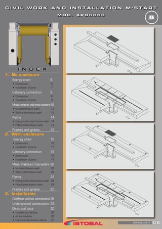
1. No enclosure
Energy chain 6
• Dimensions 6
• Installation of parts 7
Catenary connection 8
• Dimensions 8
• Installation of parts 9
Measurementsandcrosssections 10
• No underchassis wash 10
• With underchassis wash 12
Piping 14
• Overground underchassis wash 14
• Fitted underchassis wash 14
Frames and grates 15
2. With enclosure
Energy chain 16
• Dimensions 16
• Installation of parts 17
Catenary connection 18
• Dimensions 18
• Installation of parts 19
Measurementsandcrosssections 20
• No underchassis wash 20
• With underchassis wash 22
Piping 24
• Overground underchassis wash 24
• Fitted underchassis wash 24
Frames and grates 25
3. Installation
Overhead service connections 26
Underground connections 28
Electrical data 30
• Installed on machine 30
• on the machine 30
• Electrical distribution cabinet 31
M O D . 4 P D 6 0 0 0
2. SAFETY 2
SAFE PRACTICE AND SAFETY RULES
To guarantee your safety, please cooperate with the company at all times and obey the safety rules detailed here
to help ensure that accidents are avoided. (Article 29. Safety at Work Act). The following list of obligations shall
be respected by all workers carrying out work whether directly employed by ISTOBAL or subcontracted.
• Please make proper use of the personal protection equipment provided.
• Follow the instructions of your superiors, and any indications given by the person responsible for the
facility.
• Keep tools and personal and collective protection equipment in good order. If you observe any deterioration
in them, advise your superior immediately.
• Keep the work site clean and tidy.
• Advise your superiors and colleagues of any danger or risk that you perceive on the facility. In case of
serious and imminent risk, do as indicated above while also ceasing to perform any activity which may add
to such risk.
PREVENTIVE MEASURES
ISTOBAL, S.A. personnel and workers subcontracted by the company are to take into account the following
preventive measures while carrying out work:
• Hand-held ladders are not permitted for performing jobs. For work where use of a scaffold is not physically
possible or where its use would be an added risk, a platform step ladder is to be used.
• If a certified scaffold is used, follow the manufacturer's assembly instructions closely. Make sure it is in
perfect condition before use. Do not place it near power lines. If the scaffold is moveable, put the brakes on
all the wheels and use securing bars to stop it moving unexpectedly. Do not move the scaffold with workers
on it. Do not leave tools or materials lying around on the scaffold.
• If a platform step ladder is used, it must only be used by duly trained and authorised personnel. Make sure
that it is used in accordance with the instructions supplied with it.
• All waste generated is to be collected and removed from the work area as and when it is generated. The
work area should be kept as clean as possible at all times.
• Make sure the work area is organised - do not leave materials and tools lying around as these could cause
accidents.
• When materials are being loaded and unloaded with winches / cranes; materials are being lifted; heavy parts
are being mounted, etc., make sure there are no workers underneath. Check this before starting to move
anything.
CONDUCT ON SITE
• Station your vehicle in designated parking zones. Turn off the engine. Parking is not permitted in classified
areas or where the vehicle would obstruct the passage of persons or vehicles.
• Inform the supervisor or person responsible for the facility of the presence of the vehicle and why it is
there.
• Before starting work, put up signs and cordon off the areas where you will be setting up equipment such as
winches, compressors, etc.
• After the work is completed, remove leftover waste from the work area, such as plastic, cardboard, wood,
etc.
• Collect your tools and other equipment.
• Inform the Supervisor or person responsible for the facility that the work is completed and what the situation
is now.
PROTECTION EQUIPMENT
Personal and collective protection equipment used should be appropriate to the task, certified with the mark,
and display the corresponding inspection dates.
2
GB
3. SAFETY2
Personal protection equipment should give effective protection against the risks they are intended for. Such
equipment should not constitute a risk in itself nor cause unnecessary inconvenience. The equipment should:
• Respond to the conditions existing in the workplace.
• Take into account the anatomy, physiology, and state of health of the operator.
• Fit the bearer properly after the pertinent adjustments.
• Where multiple risks are involved which require several types of personal protection equipment to be
used together, they should be mutually compatible and maintain their level of efficiency in relation to the
corresponding risk or risks.
PERSONAL PROTECTION EQUIPMENT
COMPULSORY PROTECTION
Safety footwear.
Mechanical protection, waterproof, and with a dielectric
sole, anti-slip, and anti-perforation protection.
High visibility reflective vest.
Safety helmet.
Safety gloves.
OTHER PROTECTION DEPENDING ON THE WORK TO BE DONE
Tool belt.
3
GB
CIVILWORKANDINSTALLATION
4. SAFETY 2
PERSONAL PROTECTION EQUIPMENT
OTHER PROTECTION DEPENDING ON THE WORK TO BE DONE
Safety harness.
For work at a height of 2 m. and above.
Back support belt.
For tasks which require unusual positions to be adopt-
ed, or straining.
High impact safety goggles.
Use of drills, radial saws, etc.
Ear protection.
Use of drills, radial saws, etc.
Welding screens and masks with metal smoke filter.
Use of welding sets.
4
GB
5. SAFETY2
COLLECTIVE PROTECTION EQUIPMENT
Safety tape and cones
To indicate and cordon off the work area.
No entry sign.
To prevent unauthorized access, and indicate the
need for PPE to be worn.
Portable fire extinguisher.
Fire blankets
For work generating heat (welding, radial saws,
etc.).
5
GB
CIVILWORKANDINSTALLATION
6. 6
G B
NO ENCLOSURE
Between rails: 2700±5
Between rails: 2854±5
Between rails: 2500±5
No enclosure
Energy chain
Dimensions
The distance between the underside of the foot and the floor must not exceed 10 mm.
If the space K or L is smaller than recommended (500 mm), you will need to install the anti-smashing
system and wire or rubber switch.
Z
Y
Detail Z
Detail Y
K D
B
E
M
C
N
P
Q
A
F
H
L
Measurements in mm.
Left side connection
Right side connection
7. 7
G B
CIVILWORKANDINSTALLATION
NO ENCLOSURE
Y
Installation of parts
A Max. vehicle height 2300 2500 2700
B Max. vehicle width 2400
C Rail length 9000 10000 9000 10000 9000 10000
D Chassis width 3520 3520 3520 3520 3520 3520
E
Recommended 4520 4520 4520 4520 4520 4520
Minimum 4000 4000 4000 4000 4000 4000
Without cutting supporting arm 4924 4924 4924 4924 4924 4924
F Chassis height 3113 3113 3313 3313 3513 3513
H
Recommended 2260 2260 2260 2260 2260 2260
Minimum 2040 2040 2040 2040 2040 2040
Without cutting supporting arm 2664 2664 2664 2664 2664 2664
K
Recommended 500 500 500 500 500 500
Minimum 280 280 280 280 280 280
Without cutting supporting arm 904 904 904 904 904 904
L
Recommended 500 500 500 500 500 500
Minimum 200 200 200 200 200 200
M Max. vehicle length 6000 7000 6000 7000 6000 7000
N Bay length 9500 10500 9500 10500 9500 10500
P Between centres of posts 4320 4820 4320 4820 4320 4820
Q Between centres of rails 2854 2854 2854 2854 2854 2854
Y Between centring guides 2050 2050 2050 2050 2050 2050
Measurements in mm.
8. 8
G B
NO ENCLOSURE
The distance between the underside of the foot and the floor must not exceed 10 mm.
If the space K or L is smaller than recommended (500 mm), you will need to install the anti-smashing
system and wire or rubber switch. Measurements in mm.
Catenary connection
Dimensions
Between rails: 2700±5
Between rails: 2854±5
Between rails: 2500±5
Z
Y
Detail Z
Detail Y
K D
B
E
M
C
N
P
Q
A
F
H
L
Left side connection
Right side connection
9. 9
G B
CIVILWORKANDINSTALLATION
NO ENCLOSURE
Y
Installation of parts
A Max. vehicle height 2300 2500 2700
B Max. vehicle width 2400
C Rail length 9000 10000 9000 10000 9000 10000
D Chassis width 3520 3520 3520 3520 3520 3520
E
Recommended 4520 4520 4520 4520 4520 4520
Minimum 4000 4000 4000 4000 4000 4000
Without cutting supporting arm 4920 4920 4920 4920 4920 4920
F Chassis height 3113 3113 3313 3313 3513 3513
H
Recommended 2260 2260 2260 2260 2260 2260
Minimum 2040 2040 2040 2040 2040 2040
Without cutting supporting arm 2664 2664 2664 2664 2664 2664
K
Recommended 500 500 500 500 500 500
Minimum 280 280 280 280 280 280
Without cutting supporting arm 904 904 904 904 904 904
L
Recommended 500 500 500 500 500 500
Minimum 200 200 200 200 200 200
M Max. vehicle length 6000 7000 6000 7000 6000 7000
N Bay length 9500 10500 9500 10500 9500 10500
P Between centres of posts 3950 4950 3950 4950 3950 4950
Q Between centres of rails 2854 2854 2854 2854 2854 2854
Y Between centring guides 2050 2050 2050 2050 2050 2050
Measurements in mm.
10. 10
G B
NO ENCLOSURE
Measurements and cross sections
No underchassis wash
A Max. vehicle height 2300 2500 2700
B Max. vehicle width 2400
C Rail length 9000 10000 9000 10000 9000 10000
N Bay length 9500 10500 9500 10500 9500 10500
Q Between centres of rails 2854 2854 2854 2854 2854 2854
S Bay width 4830 4830 4830 4830 4830 4830
T Distance connection box (Energy chain) 4926 5426 4926 5426 4926 5426
W Length of entry grid, no Under chassis
wash 3500 4500 3500 4500 3500 4500
Surface of bay treated with non-slip finish.
Any guarantees as to the dimensions of the concrete beds depend on the floor being properly compacted.
The dimensions of the frames and grates can be consulted on page 15.
A
B
C C’
B’
D’D
A’
S
T
N
W
Q
Measurements in mm.
11. 11
G B
CIVILWORKANDINSTALLATION
NO ENCLOSURE
Energy chain or catenary connection, right or left (depending on the layout of the facility).
SECTION A - A’
SECTION B - B’
SECTION C - C’
SECTION D - D’
HEA Section 100x9000 mm
Not supplied by Istobal SA
Rebar mat 150x150x6 mm B 500 s
Rebar mat 150x150x6 mm B 500 s
Rebar mat 150x150x6 mm B 500 s Rebar mat 150x150x6 mm B 500 s
Rebar mat 150x150x6 mm B 500 s
PVC pipe D160 mm LPN 30x3 mm
Drain pipe D50 mm
Hollow brick wall 250x120x90
laid with M-40 morter
Measurements in mm.
Concrete FCK=25 n/mm2
Macadam
12. 12
G B
NO ENCLOSURE
A
B
C C’
B’
D’D
A’
With underchassis wash
A Max. vehicle height 2300 2500 2700
B Max. vehicle width 2400
C Rail length 9000 10000 9000 10000 9000 10000
N Bay length 9500 10500 9500 10500 9500 10500
Q Between centres of rails 2854 2854 2854 2854 2854 2854
S Bay width 4830 4830 4830 4830 4830 4830
T Distance connection box (Energy chain) 4926 5426 4926 5426 4926 5426
U Length of entry grid, with Under chassis
wash 2000 3000 2000 3000 2000 3000
Surface of bay treated with non-slip finish.
Any guarantees as to the dimensions of the concrete beds depend on the floor being properly
compacted. The dimensions of the frames and grates can be consulted on page 15.
S
T
N
U
Q
Measurements in mm.
13. 13
G B
CIVILWORKANDINSTALLATION
NO ENCLOSURE
Energy chain or catenary connection, right or left (depending on the layout of the facility).
SECTION A - A’
SECTION B - B’
SECTION C - C’
SECTION D - D’
HEA Section 100x9000MM
Not supplied by Istobal SA
Rebar mat 150x150x6 mm B 500 s
Rebar mat 150x150x6 mm B 500 s
Rebar mat 150x150x6 mm B 500 s Rebar mat 150x150x6 mm B 500 s
PVC pipe D160 mm LPN 30x3 mm
Drain pipe D50 mm
Hollow brick wall
250x120x90 laid with M-40
morter
Rebar mat 150x150x6 mm B 500 s
Measurements in mm.
Concrete FCK=25 n/mm2
Macadam
14. 14
G B
NO ENCLOSURE
Piping
Overground underchassis wash
Mod. 4827400
Fitted underchassis wash
Mod. 4300400 or 4300700
Self-service command
post
Positioning by
platform
To main drain
To shop terminal for
self-service code
A Flexible PVC pipe D50 mm
B PVC pipe D160 mm
C PVC pipe D30 mm
D 1” pipe DIN 2440
1 Energy chain connection box
2 Catenary connection box
Self-service command
post
Positioning by
platform
To main drain
To shop terminal for
self-service code
Measurements in mm.
B
A
A
A
A
A
A
A
A
A
A
B
D C
D C
1 2
1 2
15. 15
G B
CIVILWORKANDINSTALLATION
NO ENCLOSURE
Frames and grates
Frame for fitted underchassis wash (not supplied by Istobal).
Grate with 820x1516mm frame ref. 2375600 (optional)
Anchoring
“L” Section 60x60x8 mm
Prefabricated guttering
Prefabricated guttering
Prefabricated guttering
Prefabricated guttering
Measurements in mm.
16. 16
G B
WITH ENCLOSURE
With enclosure
Energy chain
Dimensions
Measurements in mm.
Between rails: 2700±5
Between rails: 2854±5
Between rails: 2500±5
Left side connection
Right side connection
M
C
Q
R
P
A
G
J
H
E
Z
Detail Z
Detail Y
Y
The distance between the underside of the foot and the floor must not exceed 10 mm.
With the enclosure of 4500 mm. you will need to install the anti-smashing system and wire or rubber switch.
17. 17
G B
CIVILWORKANDINSTALLATION
WITH ENCLOSURE
Y
Measurements in mm.
A Max. vehicle height 2300 2500 2700
B Max. vehicle width 2400
C Rail length 9000 10000 9000 10000 9000 10000
E
Recommended 4520 4520 4520 4520 4520 4520
Minimum 4000 4000 4000 4000 4000 4000
Without cutting supporting arm 4924 4924 4924 4924 4924 4924
G
Recommended 3550 3550 3750 3750 3950 3950
Minimum 3150 3150 3350 3350 3550 3550
H
Recommended 2260 2260 2260 2260 2260 2260
Minimum 2040 2040 2040 2040 2040 2040
Without cutting supporting arm 2664 2664 2664 2664 2664 2664
J Height service line 3084 3084 3284 3284 3484 3484
M Max. vehicle length 6000 7000 6000 7000 6000 7000
P Between centres of posts 4320 4820 4320 4820 4320 4820
Q Between centres of rails 2854 2854 2854 2854 2854 2854
R Length bay enclosure 10100 11100 10100 11100 10100 11100
Y Between centring guides 2050 2050 2050 2050 2050 2050
Installation of parts
18. 18
G B
WITH ENCLOSURE
Catenary connection
Dimensions
Between rails: 2700±5
Between rails: 2854±5
Between rails: 2500±5
Left side connection
Right side connection
M
C
Q
R
P
A
G
J
H
E
Z
Detail Z
Detail Y
Y
Measurements in mm.
The distance between the underside of the foot and the floor must not exceed 10 mm.
With the enclosure of 4500 mm. you will need to install the anti-smashing system and wire or rubber switch.
19. 19
G B
CIVILWORKANDINSTALLATION
WITH ENCLOSURE
A Max. vehicle height 2300 2500 2700
B Max. vehicle width 2400
C Rail length 9000 10000 9000 10000 9000 10000
E
Recommended 4520 4520 4520 4520 4520 4520
Minimum 4000 4000 4000 4000 4000 4000
Without cutting supporting arm 4924 4924 4924 4924 4924 4924
G
Recommended 3550 3550 3750 3750 3950 3950
Minimum 3150 3150 3350 3350 3550 3550
H
Recommended 2260 2260 2260 2260 2260 2260
Minimum 2040 2040 2040 2040 2040 2040
Without cutting supporting arm 2664 2664 2664 2664 2664 2664
J Height service line 2364 2364 2564 2564 2764 2764
M Max. vehicle length 6000 7000 6000 7000 6000 7000
P Between centres of posts 3950 4950 3950 4950 3950 4950
Q Between centres of rails 2854 2854 2854 2854 2854 2854
R Length bay enclosure 10100 11100 10100 11100 10100 11100
Y Between centring guides 2050 2050 2050 2050 2050 2050
Y
Installation of parts
Measurements in mm.
20. 20
G B
WITH ENCLOSURE
Surface of bay treated with non-slip finish.
Any guarantees as to the dimensions of the concrete beds depend on the floor being properly
compacted. The dimensions of the frames and grates can be consulted on page 25.
A
B
C C’
B’
D’D
A’
V
Q
R
W
Measurements in mm.
Measurements and cross sections
No underchassis wash
A Max. vehicle height 2300 2500 2700
B Max. vehicle width 2400
C Rail length 9000 10000 9000 10000 9000 10000
Q Between centres of rails 2854 2854 2854 2854 2854 2854
R Length bay enclosure 10100 11100 10100 11100 10100 11100
V
Width for enclosure 4.5 m. 5000 5000 5000 5000 5000 5000
Width for enclosure 4.8 m. 5300 5300 5300 5300 5300 5300
W Length of entry grid, no Underchassis wash 3500 4500 3500 4500 3500 4500
21. 21
G B
CIVILWORKANDINSTALLATION
SECTION C - C’
SECTION D - D’
WITH ENCLOSURE
Energy chain or catenary connection, right or left (depending on the layout of the facility).
SECTION A - A’
SECTION B - B’
HEA Section 100x9000 mm
Not supplied by Istobal SA
Rebar mat 150x150x6 mm B 500 s
Rebar mat 150x150x6 mm B 500 s
Rebar mat 150x150x6 mm B 500 s
PVC pipe D160 mm LPN 30x3 mm
Drain pipe D50 mm
Hollow brick wall 250x120x90
laid with M-40 morter
AEH-400 NAEH-400 N
AEH-400 N AEH-400 N
Measurements in mm.
Concrete FCK=25 n/mm2
Macadam
Rebar mat 150x150x6 mm B 500 s Rebar mat 150x150x6 mm B 500 s
22. 22
G B
WITH ENCLOSURE
Surface of bay treated with non-slip finish.
Any guarantees as to the dimensions of the concrete beds depend on the floor being properly
compacted. The dimensions of the frames and grates can be consulted on page 25.
With underchassis wash
Measurements in mm.
V
Q
R
U
A
B
C C’
B’
D’D
A’
A Max. vehicle height 2300 2500 2700
B Max. vehicle width 2400
C Rail length 9000 10000 9000 10000 9000 10000
Q Between centres of rails 2854 2854 2854 2854 2854 2854
R Length bay enclosure 10100 11100 10100 11100 10100 11100
U Length of entry grid, with Under chassis
wash 2000 3000 2000 3000 2000 3000
V
Width for enclosure 4.5 m. 5000 5000 5000 5000 5000 5000
Width for enclosure 4.8 m. 5300 5300 5300 5300 5300 5300
23. 23
G B
CIVILWORKANDINSTALLATION
WITH ENCLOSURE
Energy chain or catenary connection, right or left (depending on the layout of the facility).
SECTION A - A’
SECTION B - B’
SECTION C - C’
SECTION D - D’
HEA Section 100x9000 mm
Not supplied by Istobal SA
Rebar mat 150x150x6 mm B 500 s
Rebar mat 150x150x6 mm B 500 s
PVC pipe D160 mm
LPN 30x3 mm
AEH-400 NAEH-400 N
AEH-400 N AEH-400 N
Drain pipe D50 mm
Hollow brick wall
250x120x90 laid with M-40
morter
Rebar mat 150x150x6 mm B 500 s
Rebar mat 150x150x6 mm B 500 s
Rebar mat 150x150x6 mm B 500 s
Measurements in mm.
Concrete FCK=25 n/mm2
Macadam
24. 24
G B
WITH ENCLOSURE
A Flexible PVC pipe D50 mm
B PVC pipe D160 mm
C PVC pipe D30 mm
D 1” pipe DIN 2440
1 Energy chain connection box
2 Catenary connection box
Piping
Overground underchassis wash
Mod. 4827400
Measurements in mm.
Fitted underchassis wash
Mod. 4300400 or 4300700
Self-service command
post
Positioning by
platform
To main drain
To shop terminal for
self-service code
Self-service
command post
Positioning by
platform
To main drain
To shop terminal for
self-service code
B
A
A
A
A
A
A
A
A
A
1 2
A
B
D C
D C
1 2
25. 25
G B
CIVILWORKANDINSTALLATION
WITH ENCLOSURE
Frames and grates
Frame for fitted underchassis wash (not supplied by Istobal).
Grate with 820x1516mm frame ref. 2375600 (optional)
Anchoring
Prefabricated guttering
Prefabricated guttering
“L” Section 60x60x8 mm
Prefabricated guttering
Prefabricated guttering
Measurements in mm.