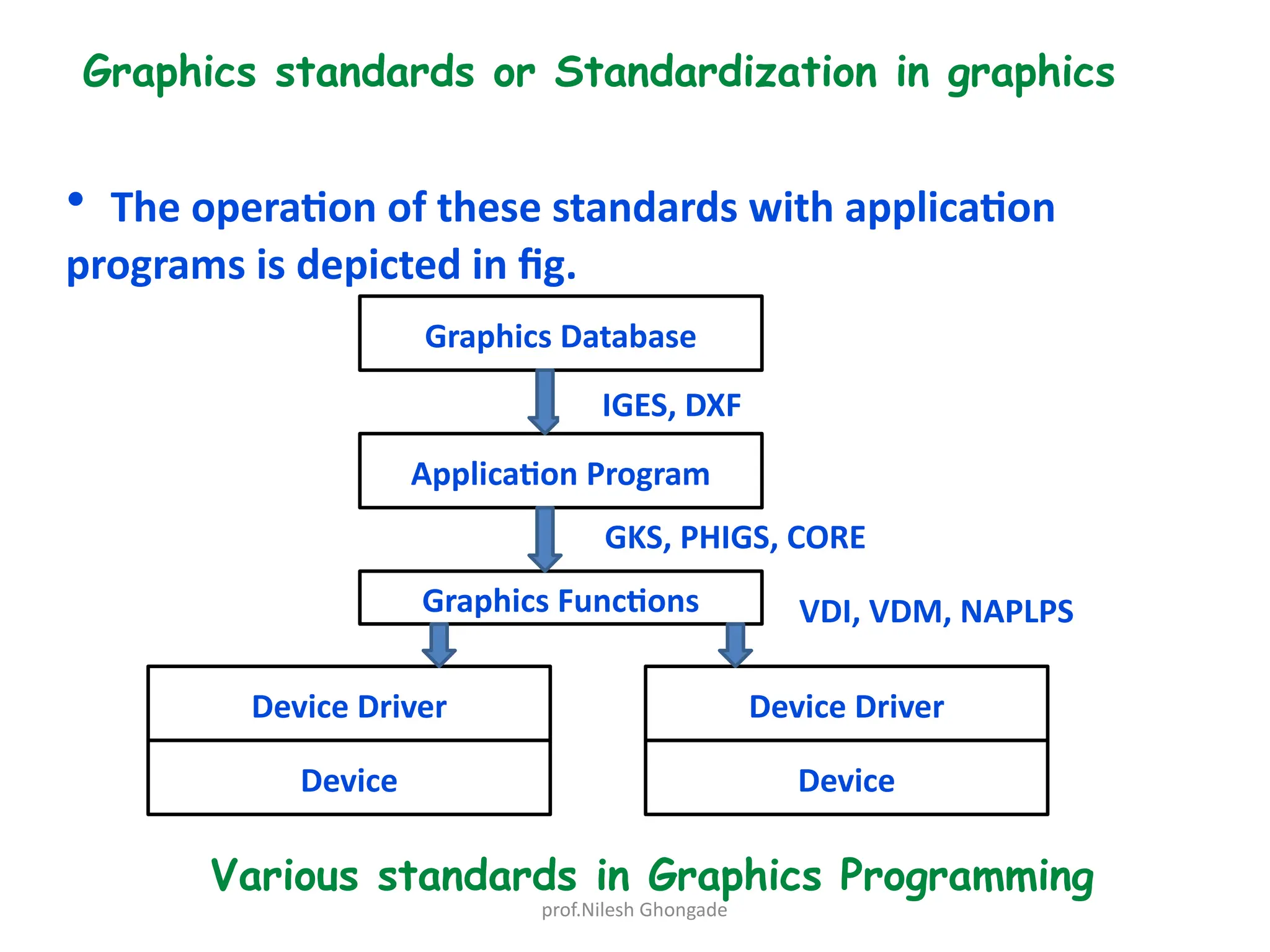
prof.Nilesh Ghongade
Chapter 2: Techniques for Geometric modeling
• Graphics standards
• Parametric representation of geometry
• Bezier Curve
• Cubic Spline curve
• B- Spline curve
• Geometrical modeling techniques
prof.Nilesh Ghongade
Graphics Package
It include s programs to generate and manipulate the image on the screen.
It also allow to the user to interact with computer
According to Newman and Sproull, there are 6 basic characteristics that a graphics
package must have:
1. Simplicity
2. Consistency
3. Completeness
4. Robustness
5. Performance
6. Economy.
Function of graphics package
7. Generation of Graphics Elements
8. Transformation (Alterations of a Graphics Element)
9. Display control and windowing function
10. Segmentation (Selective Editing)
11. User Input Function
prof.Nilesh Ghongade
Graphics standards or Standardization in graphics
• There should be compatibility between various software
elements and hardware /software.
• This is achieved by maintaining proper interface standards at
various levels.
• Following are some of them:
- GKS (Graphical Kernel System)
- PHIGS (Programmer’s Hierarchical Interface for Graphics)
- IGES (Initial Graphics Exchange Specification)
- DXF ( Drawing Exchange Format)
-- STEP ( Standard for the Exchange of Product Model data)
-- VDI ( Virtual Device interface)
-- VDM ( Virtual Interface Metafile)
-- NAPLPS ( North American Presentation Level Protocol Syntax)
prof.Nilesh Ghongade
Graphics standards or Standardization in graphics
• The operation of these standards with application
programs is depicted in fig.
Application Program
Graphics Database
Device
Device Driver
Graphics Functions
Device Driver
Device
Various standards in Graphics Programming
IGES, DXF
GKS, PHIGS, CORE
VDI, VDM, NAPLPS
prof.Nilesh Ghongade
Geometrical modeling techniques
• Geometrical modeling presentation/ types of geometrical model
> Wire Frame Model
> Surface Model
> Solid Model
• Modeling Technique
> Primitive based modeling
(Constructive Solid Geometry)
> Variational Modeling
> Feature based modeling
> Parametric Modeling
> Constrained driven Modeling
• Use of Modeling in :
> Assembly design and modeling
> Mechanism/ Kinematic Analysis
> Mock-up Analysis
> Computer Aided Drafting
> NC Part Programming and Machining
> CAQC
prof.Nilesh Ghongade
Parametric Modelling
• Parametric is a term used to describe a dimension’s ability to change the shape of model geometry as soon
as the dimension value is modified.
• Feature-based is a term used to describe the various components of a model. For example, a part can
consists of various types of features such as holes, grooves, fillets, and chamfers. A ‘feature’ is the basic
unit of a parametric solid model.
Parametric modelling:
> uses the computer to design objects or systems that model component attributes with real world
behaviour.
> Parametric models use feature-based, solid and surface modelling design tools to manipulate the system
attributes. One of the most important features of parametric modelling is that attributes that are
interlinked automatically change their features.
> In other words, parametric modelling allows the designer to define entire classes of shapes, not just
specific instances. Before the advent of parametrics, editing the shape was not an easy task for designers.
> For example, to modify a 3D solid, the designer had to change the length, the breadth and the height.
However, with parametric modelling, the designer need only alter one parameter; the other two
parameters get adjusted automatically. So, parametric models focus on the steps in creating a shape and
parameterize them. This benefits product design engineering services providers a lot.
The Parametric Modelling Process
• Parametric models are built from a set of mathematical equations. For parametric models to have any
legitimacy, they must be based on real project information. It is the modernity of the information
examination techniques and the breadth of the hidden undertaking information which decides the viability
of a modelling solution.
• There are two popular parametric representation models:
prof.Nilesh Ghongade
Constructive Solid Geometry (CSG)
• CSG defines a model in terms of combining basic (primitive) and
generated (using extrusion and sweeping operation) solid shapes. It uses
Boolean operations to construct a model. CSG is a combination of 3D
solid primitves (for example a cylinder, cone, prism, rectangle or sphere)
that are then manipulated using simple Boolean operations.
Boundary Representation (BR)
• In BR, a solid model is formed by defining the surfaces that form its
spatial boundaries (points, edges, etc.) The object is then made by
joining these spatial points. Many Finite Element Method (FEM)
programs use this method, as it allows the interior meshing of the
volume to be more easily controlled.
prof.Nilesh Ghongade
Advantages
These are the benefits offered by 3D parametric modelling
over traditional 2D drawings:
• Capability to produce flexible designs
• 3D solid models offer a vast range of ways to view the model
• Better product visualization, as you can begin with simple
objects with minimal details
• Better integration with downstream applications and
reduced engineering cycle time
• Existing design data can be reused to create new designs
• Quick design turnaround, increasing efficiency
prof.Nilesh Ghongade
Parametric Modelling Tools
There are many software choices available in the market today for parametric
modelling. On a broad level, this software can be categorized as:
Small scale use
Large scale use
Industry specific modelling
Of the three, the last category (viz. industry specific parametric software) has
gained in popularity. A few of the leading industry software is:
SolidWorks
Introduced in 1995 as a low-cost competitor to the other parametric modeling
software products, SolidWorks was purchased in 1997 by Dassault Systemes. It is
primarily used in mechanical design applications and has a strong following in the
plastics industry.
CATIA
Dassault Systemes created CATIA in France in the late 1970s. This sophisticated
software is widely used in the aeronautic, automotive, and shipbuilding industries.
Siemens NX
NX, previously known as Unigraphics, was purchased by McDonnell Douglas in
1977. The latest version of NX enhances efficiency throughout the product life
cycle. It is an integrated product design, engineering and manufacturing solution.
prof.Nilesh Ghongade
Theory of Wire frame or Curve Design
• Types of Wireframe model
Curves
Analytical
Curves
Synthetic
Curves
Explicit
Y = f(x)
Implicit
f(x,y) = 0
Inter
polation
Approxi
mation
Parametric Curves
Non Parametric
Curves
Q.1 Differentiate between Non parametric and Parametric curves
Q 2. Parametric representation of analytical curves
prof.Nilesh Ghongade
Synthetic curves
• Characteristics of synthetic curves
> is defined by a set of data point
> mathematically it is treated as curve fitting problems, can
either interpolate or approximated
> can generate smooth curves which are normally used in
engineering applications
> A very long curve is difficult to synthesized so theses are
synthesized using multiple segments.
> there are three types of continuities : points, Tangent and
curvature.
• there are three types of synthetic curves which are normally
used in engg practice:
> Hermite Cubic Curve
> Bezier curve
> B – Spline Curve
prof.Nilesh Ghongade
Hermite Cubic Curve
• having a cubic degree
P(u) = Lu3 + Mu2 + Nu + Q
To determine P(u) minimum four points are required
Derivation see notes..
prof.Nilesh Ghongade
Bezier curves
• Most of engg design requires free from shapes and hence a curve with
approximation technique is more useful.
> Bezier curve represents such curves with approximations
> can have any degree depending upon the number of control points.
> if it is controlled by (n-1) controlled points it will generate nth degree
Bezier Curve
> these controlled points describe the control polygon which is called
convex hull.
> this curve passes through 1st
and last point and is tangent to first and
last segment.
prof.Nilesh Ghongade
B-Spline curves
• Fine control over the curve may be obtained by two approaches
1. High degree of Polynomial
2. combining certain low degree polynomial with suitable end
condition
B- spline functions are made independent on ‘N’ and being defined in terms
of by another parameter ‘K’ , which in turn defines the degree of curve
(k-1)

Chapter-2.ppt lof design engineering here

  • 1.
    prof.Nilesh Ghongade Chapter 2:Techniques for Geometric modeling • Graphics standards • Parametric representation of geometry • Bezier Curve • Cubic Spline curve • B- Spline curve • Geometrical modeling techniques
  • 2.
    prof.Nilesh Ghongade Graphics Package Itinclude s programs to generate and manipulate the image on the screen. It also allow to the user to interact with computer According to Newman and Sproull, there are 6 basic characteristics that a graphics package must have: 1. Simplicity 2. Consistency 3. Completeness 4. Robustness 5. Performance 6. Economy. Function of graphics package 7. Generation of Graphics Elements 8. Transformation (Alterations of a Graphics Element) 9. Display control and windowing function 10. Segmentation (Selective Editing) 11. User Input Function
  • 3.
    prof.Nilesh Ghongade Graphics standardsor Standardization in graphics • There should be compatibility between various software elements and hardware /software. • This is achieved by maintaining proper interface standards at various levels. • Following are some of them: - GKS (Graphical Kernel System) - PHIGS (Programmer’s Hierarchical Interface for Graphics) - IGES (Initial Graphics Exchange Specification) - DXF ( Drawing Exchange Format) -- STEP ( Standard for the Exchange of Product Model data) -- VDI ( Virtual Device interface) -- VDM ( Virtual Interface Metafile) -- NAPLPS ( North American Presentation Level Protocol Syntax)
  • 4.
    prof.Nilesh Ghongade Graphics standardsor Standardization in graphics • The operation of these standards with application programs is depicted in fig. Application Program Graphics Database Device Device Driver Graphics Functions Device Driver Device Various standards in Graphics Programming IGES, DXF GKS, PHIGS, CORE VDI, VDM, NAPLPS
  • 5.
    prof.Nilesh Ghongade Geometrical modelingtechniques • Geometrical modeling presentation/ types of geometrical model > Wire Frame Model > Surface Model > Solid Model • Modeling Technique > Primitive based modeling (Constructive Solid Geometry) > Variational Modeling > Feature based modeling > Parametric Modeling > Constrained driven Modeling • Use of Modeling in : > Assembly design and modeling > Mechanism/ Kinematic Analysis > Mock-up Analysis > Computer Aided Drafting > NC Part Programming and Machining > CAQC
  • 6.
    prof.Nilesh Ghongade Parametric Modelling •Parametric is a term used to describe a dimension’s ability to change the shape of model geometry as soon as the dimension value is modified. • Feature-based is a term used to describe the various components of a model. For example, a part can consists of various types of features such as holes, grooves, fillets, and chamfers. A ‘feature’ is the basic unit of a parametric solid model. Parametric modelling: > uses the computer to design objects or systems that model component attributes with real world behaviour. > Parametric models use feature-based, solid and surface modelling design tools to manipulate the system attributes. One of the most important features of parametric modelling is that attributes that are interlinked automatically change their features. > In other words, parametric modelling allows the designer to define entire classes of shapes, not just specific instances. Before the advent of parametrics, editing the shape was not an easy task for designers. > For example, to modify a 3D solid, the designer had to change the length, the breadth and the height. However, with parametric modelling, the designer need only alter one parameter; the other two parameters get adjusted automatically. So, parametric models focus on the steps in creating a shape and parameterize them. This benefits product design engineering services providers a lot. The Parametric Modelling Process • Parametric models are built from a set of mathematical equations. For parametric models to have any legitimacy, they must be based on real project information. It is the modernity of the information examination techniques and the breadth of the hidden undertaking information which decides the viability of a modelling solution. • There are two popular parametric representation models:
  • 7.
    prof.Nilesh Ghongade Constructive SolidGeometry (CSG) • CSG defines a model in terms of combining basic (primitive) and generated (using extrusion and sweeping operation) solid shapes. It uses Boolean operations to construct a model. CSG is a combination of 3D solid primitves (for example a cylinder, cone, prism, rectangle or sphere) that are then manipulated using simple Boolean operations. Boundary Representation (BR) • In BR, a solid model is formed by defining the surfaces that form its spatial boundaries (points, edges, etc.) The object is then made by joining these spatial points. Many Finite Element Method (FEM) programs use this method, as it allows the interior meshing of the volume to be more easily controlled.
  • 8.
    prof.Nilesh Ghongade Advantages These arethe benefits offered by 3D parametric modelling over traditional 2D drawings: • Capability to produce flexible designs • 3D solid models offer a vast range of ways to view the model • Better product visualization, as you can begin with simple objects with minimal details • Better integration with downstream applications and reduced engineering cycle time • Existing design data can be reused to create new designs • Quick design turnaround, increasing efficiency
  • 9.
    prof.Nilesh Ghongade Parametric ModellingTools There are many software choices available in the market today for parametric modelling. On a broad level, this software can be categorized as: Small scale use Large scale use Industry specific modelling Of the three, the last category (viz. industry specific parametric software) has gained in popularity. A few of the leading industry software is: SolidWorks Introduced in 1995 as a low-cost competitor to the other parametric modeling software products, SolidWorks was purchased in 1997 by Dassault Systemes. It is primarily used in mechanical design applications and has a strong following in the plastics industry. CATIA Dassault Systemes created CATIA in France in the late 1970s. This sophisticated software is widely used in the aeronautic, automotive, and shipbuilding industries. Siemens NX NX, previously known as Unigraphics, was purchased by McDonnell Douglas in 1977. The latest version of NX enhances efficiency throughout the product life cycle. It is an integrated product design, engineering and manufacturing solution.
  • 10.
    prof.Nilesh Ghongade Theory ofWire frame or Curve Design • Types of Wireframe model Curves Analytical Curves Synthetic Curves Explicit Y = f(x) Implicit f(x,y) = 0 Inter polation Approxi mation Parametric Curves Non Parametric Curves Q.1 Differentiate between Non parametric and Parametric curves Q 2. Parametric representation of analytical curves
  • 11.
  • 12.
  • 13.
  • 14.
    prof.Nilesh Ghongade Synthetic curves •Characteristics of synthetic curves > is defined by a set of data point > mathematically it is treated as curve fitting problems, can either interpolate or approximated > can generate smooth curves which are normally used in engineering applications > A very long curve is difficult to synthesized so theses are synthesized using multiple segments. > there are three types of continuities : points, Tangent and curvature. • there are three types of synthetic curves which are normally used in engg practice: > Hermite Cubic Curve > Bezier curve > B – Spline Curve
  • 15.
    prof.Nilesh Ghongade Hermite CubicCurve • having a cubic degree P(u) = Lu3 + Mu2 + Nu + Q To determine P(u) minimum four points are required Derivation see notes..
  • 16.
    prof.Nilesh Ghongade Bezier curves •Most of engg design requires free from shapes and hence a curve with approximation technique is more useful. > Bezier curve represents such curves with approximations > can have any degree depending upon the number of control points. > if it is controlled by (n-1) controlled points it will generate nth degree Bezier Curve > these controlled points describe the control polygon which is called convex hull. > this curve passes through 1st and last point and is tangent to first and last segment.
  • 17.
    prof.Nilesh Ghongade B-Spline curves •Fine control over the curve may be obtained by two approaches 1. High degree of Polynomial 2. combining certain low degree polynomial with suitable end condition B- spline functions are made independent on ‘N’ and being defined in terms of by another parameter ‘K’ , which in turn defines the degree of curve (k-1)