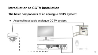
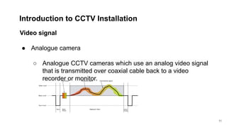
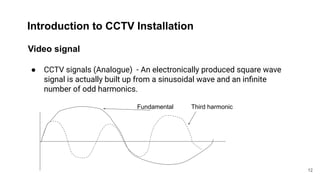
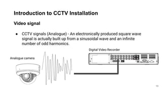
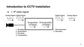
Cube
Training
Introduction
to CCTV
1
COVID-19
2
Introduction to CCTV Installation
What is CCTV?
Closed Circuit Television (CCTV):
This is the technology behind capturing images from a video source at one
end of the circuit and transmitting it through some type of transmission
media to a receiving unit on the other end, for the purpose of security and
monitoring activities.
3
Introduction to CCTV Installation
The basic components of an analogue CCTV system:
There are four basic components in a CCTV system:
● Video Source (Camera)
● Transmission medium
● Recording unit (DVR)
● Power Source
4
Introduction to CCTV Installation
The basic components of an analogue CCTV system:
● Video Source (Camera)
○ This is the device responsible for the monitoring and
capturing of the image (video footages).
5
Introduction to CCTV Installation
The basic components of an analogue CCTV system:
● Transmission Medium
○ The two types of cables used for the installation of Security
Cameras and Digital Video Recorders (DVRs) are UTP Cables and
RG59 Coax Siamese cable.
○ Fibre Optics.
6
Introduction to CCTV Installation
The basic components of an analogue CCTV system:
● Recording units
○ DVR (Digital Video Recorder)
○ NVR (Network Video Recorder)
○ Servers, Cloud Storage
7
Introduction to CCTV Installation
The basic components of an analogue CCTV system:
● Power supply unit
8
Introduction to CCTV Installation
The basic components of an analogue CCTV system:
● Power supply unit
9
Introduction to CCTV Installation
The basic components of an analogue CCTV system:
● Assembling a basic analogue CCTV system.
10
Introduction to CCTV Installation
Video signal
● Analogue camera
○ Analogue CCTV cameras which use an analog video signal
that is transmitted over coaxial cable back to a video
recorder or monitor.
11
12
Introduction to CCTV Installation
Video signal
● CCTV signals (Analogue) - An electronically produced square wave
signal is actually built up from a sinusoidal wave and an infinite
number of odd harmonics.
12
Fundamental Third harmonic
13
Introduction to CCTV Installation
Video signal
● CCTV signals (Analogue) - An electronically produced square wave
signal is actually built up from a sinusoidal wave and an infinite
number of odd harmonics.
13
Digital Video Recorder
Analogue camera
14
Introduction to CCTV Installation
14
Video signal
Power supply unit
Camera
DC power cable 12V
DC or 24V AC
Coaxial cable
Digital Video Recorder
15
Introduction to CCTV Installation
15
Wave form
A sequence of electrical waves known
as the television picture signal.
Signal - Analogue
Video signal
16
Introduction to CCTV Installation
16
Analogue video is commonly
distributed as a composite signal, this
video information is generated by
sampling the intensity of the original
continuous analog video signal I (x, y,
t) in three dimensions. The spatial
component of the video signal is
sampled in the horizontal and vertical
dimensions (x, y), and the temporal
component is sampled in the time
dimension (t).
Video signal
17
18
Introduction to CCTV Installation
18
For coding and decoding purpose there are three different coding systems are
used worldwide. These systems – PAL, NTSC and SECAM – are all mutually
incompatible.
1. The NTSC (the National Television Standards Committee) system is used
in North and South America and Japan.
2. SECAM (SEquentiel Couleur Avec Memoire) is used in France and Eastern
Europe
3. PAL (Phase Alternating Line) is used in the UK and the rest of Europe.
Video signal
19
Introduction to CCTV Installation
19
Interlaced Scanning
This consists of two sets of lines. One set is scanned first, and the lines are so
laid down that an equal empty space is maintained between lines. The second
set is laid down after the first and is so positioned that its lines fall precisely in
the empty spaces of the first set. The area of the image is thus scanned twice,
but each point in the area is passed over only once. This is known as interlaced
scanning, and it is used in all the standard television broadcast services of the
world.
Video signal
20
Introduction to CCTV Installation
20
Video signal
21
Introduction to CCTV Installation
21
Progressive Scanning
Progressive scanning is a format of displaying, storing, or transmitting moving
images in which all the lines of each frame are drawn in sequence.
Source: Wikipedia
22
Introduction to CCTV Installation
22
Progressive Scanning Vs Interlaced Scanning
Source: Wikipedia
23
Introduction to CCTV Installation
23
How does analog and digital recording work?
When we capture that video footages in a way that represents all the
possible frequencies, we're recording in analogue; when we use DVR to
translate the video into a series of numbers that approximate what we're
seeing, we're recording in digital.
24
Introduction to CCTV Installation
24
1
0
1
0
Digital Video Recorder
(DVR)
Analogue signal Digital signal
Video signal
25
Introduction to CCTV Installation
Video signal
Digital camera
RJ45 Slot
26
Introduction to CCTV Installation
Video signal
Digital camera
IP camera
Analogue signals
Digital signals
H.265 +
H.265
27
Introduction to CCTV Installation
● What are the factors that determine the quality of a CCTV video
image?
○ There are many factors affect video quality including
■ Type of the construction of cable
■ The cable length
■ The way the bends have been formed
■ The type and the quality of the connectors
27
28
Introduction to CCTV Installation
● 1. What are most common cables used in CCTV application?
○ The engineer should understand the characteristic of the cable,
every cable have different characteristics.
○ The main types of cables used in CCTV applications.
■ Coaxial cable
■ Ethernet cable or network cable
■ Fibre-optic
28
Introduction to CCTV Installation
Coaxial cable
29
Introduction to CCTV Installation
30
Coaxial cable is the most common type of cable used in many
CCTV application. The coaxial cable is designed to meet the
unique propagation requirements of radio frequency signals,
offering constant impedance over a range of frequencies and
protection against unwanted noise.
The video signal travels through the inner core and return via the
braided screen. The copper braid is not only the path for the video
to return, but it also serves as a shield for any unwanted noise.
Introduction to CCTV Installation
31
The video signal travels through the inner core and return via the
braided screen. The copper braid is not only the path for the video
to return, but it also serves as a shield for any unwanted noise.
As the copper braid is earthed the return signal will use any path to
return.
Introduction to CCTV Installation
32
How to maintain the integrity of the coaxial cable?
Let's look at the structure of a coaxial cable.
Inner insulating sleeve
Copper core
Copper braid
Insulating outer sleeve
33
Introduction to CCTV Installation
Copper core
Inner copper is used to transmit video signal.
34
Introduction to CCTV Installation
Inner insulating sleeve
The inner sleeve of the coaxial cable performs an important role. It
forms an insulation between inner core and copper braid. It also
forms a dielectric between the conductors which introduces a
capacitive element into the cable.
35
Introduction to CCTV Installation
Are there different types of coaxial cable?
Yes, not all coaxial cable has 75 Ohms impedance. CCTV
equipment is designed to have 75 Ohms input and output
impedances.
36
Introduction to CCTV Installation
How to maintain the integrity of the coaxial cable?
1. Coaxial cable is more than a simple piece of wire, and only
functions correctly when certain criteria have been met.
Never join two coaxial cable using connector blocks.
As this may electrical sound fine, it breaks all the rules of RF
theory and exposes the inner core to RFI.
2. The coaxial should be joined using couplers.
3. As CCTV equipments use 75 Ohms impedance, the correct
coaxial cable to use is the one with 75 Ohms. e.g. RG59
37
Introduction to CCTV Installation
How to maintain the integrity of the coaxial cable?
3. There are number of coaxial cables which don’t use 75 Ohms.
For example RG58 uses 50 Ohms.
Cable
type
Max run
length
Impedance Loss/100m
At 5 MHz
URM - 70 250m 75 Ohms 3.31 dB
RG59 350m 75 Ohms 2.25 dB
RG-11 700m 75 Ohms 1.4 dB
38
Introduction to CCTV Installation
Copper braid
The signal returns via copper braid, however, it is not the case
always. As this is earthed, the signal can return using any source.
The copper braid works as a shield for unwanted noise or EMI
(Electromagnetic interference).
39
Introduction to CCTV Installation
How to maintain the integrity of the coaxial cable?
4. All CCTV signal cable installation should comply with current
codes of practice as laid down in BS 7671. Especially in relation to
electrical segregation of low and high voltage cables.
5. In order to prevent damage to the inner sleeve, coaxial cable
should not have any serve bends. The radius of all bends is no
tighter than five times the diameter of the cable.
40
Introduction to CCTV Installation
How to maintain the integrity of the coaxial cable?
41
Introduction to CCTV Installation
How to maintain the integrity of the coaxial cable?
6. The difference between earthing can cause , the current will flow
through the low impedance screen, this will cause ripple rolling
vertically through the picture. This is known as hum bar.
42
Introduction to CCTV Installation
+ 30V - 10V
Ground loop correction transformer
Introduction to CCTV Installation
Ethernet cable & Twisted pair cable
43
Introduction to CCTV Installation
44
As the name implies, this cable
comprises two cores which are
wrapped around each other. The
number of twists per metre varies. It
is better to connect video via the pair
that has more twists.
In a UTP cable, the pin 1 and pin 2
or white orange and orange have
more twists. Hence it is better to use
them for video transmission.
Introduction to CCTV Installation
45
In most cases, twisted pair cable is
not screened and known as an
unshielded twisted pair (UTP).
However, it is better to use screened
network cable for CCTV or known as
shielded pairs.
Introduction to CCTV Installation
46
What are the advantages of using Ethernet cable in a CCTV
application?
The primary advantage of using a CAT cable is that much longer
cable run is possible. It always works very well in situations where
excess electromagnetic interference is present.
Introduction to CCTV Installation
47
What are the disadvantages of using Ethernet cable in a CCTV
application?
● The balun is required.
● The wrong cable selection can lead to issues.
● It is relatively expensive.
Introduction to CCTV Installation
Fibre optics
48
Introduction to CCTV Installation
Fibre optics
49
The signal travels in the form of light through fibre-optics cables.
The fibre optics cable has no problem with RFI, EMI, lighting etc.
The signal travels in the form of light through fibre-optics cables.
The fibre optics cable has no problem with RFI, EMI, lighting etc. It
is almost impossible to tap into fibre optics.
Introduction to CCTV Installation
● 1. Exercise
○ Connect an analogue camera with a DVR and monitor.
■ Check the resolution
■ The maximum resolution with analogue camera is 0.4
M pixels.(720x576 = 414720)
■ 960H (960x576 = 552960)
■ Full HD is 2 M pixels - (1920x1080 = 2073600)
50
Introduction to CCTV Installation
● Challenges in analogue CCTV cameras
○ Low resolution
○ Maximum resolution is limited to 1000 TVL
○ Integration is difficult - e.g. Integrating with other security
devices.
○ DVR is necessary to convert the analogue signals to
digital. It is not possible to view analogue camera via
internet without a DVR or server.
51
Introduction to CCTV Installation
● 1. IP camera
○ An Internet protocol camera, or IP camera, is a type of
digital video camera commonly employed for surveillance,
and which, unlike analog closed circuit television (CCTV)
cameras, can send and receive data via a computer
network and the Internet
52
Introduction to CCTV Installation
53
Introduction to CCTV Installation
● 1. Exercise IP camera installation
○
54
Power Supply
Introduction to CCTV Installation
● 1. IP video signal
○
55
Introduction to CCTV Installation
● 1. IP video signal - Challenges
○ Latency - latency is a common problem in IP video
surveillance system.
○ IP conflict - minimum computer network knowledge
required.
○ Bigger storage requirement
○ Dependencies - Your router speed, internet speed and
other factors can influence the performance.
○ Expensive
56
Introduction to CCTV Installation
● 1. IP video signal - Challenges
○
57
Introduction to CCTV Installation
● Transmission medium
The means of transporting the captured video footages
from the camera to the recording unit.
58
Questions?
15 minutes break
Tea or coffee??
59
Questions
1. What are the advantages of an IP CCTV system?
2. What are the advantages of an analogue system?
3. What are the common cables used in CCTV application?
60
Cube Training
Practical wiring
61
BNC - (Bayonet Neill–Concelman)
● 3 piece BNC
● Twisted BNC
● 2 pcs BNC
62
How to terminate BNC
Basic tools required for each type of BNC’s.
● BNC crimp
● Side cutters
63
BNC termination
64
BNC Crimp
65
Crimping 2 piece BNC
66
Shotgun
18 AWG used in most shotgun cable for power -
67
DC lead
Camera’s end
Positive
Negative
68
Power supply
12 V DC cable
RG59 or Coaxial
69
CCTV Installation
Ethernet cable crimping
Tools required
70
CCTV Installation
Ethernet cable crimping
Step 1 : Strip cable, measure how much of the outer sheath needs to be
removed.
Strip at least 5 cm of outer sheath, make sure you do not damage the
actual cables inside.
71
CCTV Installation
Step 2 - use the correct type of cable stripper.
72
CCTV Installation
Ethernet cable crimping
73
CCTV Installation
Step 3
Untwist all of the conductors, and arrange them in the correct order.
74
CCTV Installation
Step 3
1. White-orange
2. Orange
3. White-green
4. Blue
5. White-blue
6. Green
7. White-brown
8. Brown
75
CCTV Installation
Step 4
Flatten them out with your fingers, chop them off to a length of 10 cm (Do
not use normally side cutters)
76
CCTV Installation
Step 5
Push on the end on and crimp
77
CCTV Installation
Step 6
All done
78
CCTV Installation
Basic analogue CCTV system
79
Coaxial cable
(RG59)
Twin power cable
CCTV Installation
Questions?
80
Electrical and CCTV installation
● Circuits
What is a circuit?
In electronics, a circuit is a closed path through which electrical currents
can flow. The flow of electrical current through a flashlight illustrates the
idea.
81
Electrical and CCTV installation
82
Electrical and CCTV installation
Three parts of the flashlight comprise the circuit: the battery, which supplies
power, a bulb, which produces light when connected to the battery, and a switch,
which can either be on (connected) or off (disconnected). The important feature of
this circuit is that electrical currents flow through it in a loop, as illustrated in the
right part of the figure above. The rules that govern the flow of electrical current
are similar to the rules that govern the flow of certain types of fluids; and it is often
helpful to draw analogies between these flows. The following figure illustrates the
flow of blood through the human circulatory system.
83
Electrical and CCTV installation
● Voltage:
Voltage is a difference in electrical potential between two different points in a
circuit.
● Current:
Current is a flow of electrical charge through a path in the circuit. A positive
current in a direction is generated by negative charges (electrons) moving in
the opposite direction.
84
Electrical and CCTV installation
● Resistance
Resistance is a material’s tendency to resist the flow of charge (current)
85
Electrical and CCTV installation
When describing voltage, current, and resistance, a common analogy is a water
tank.
● Water = Charge
● Pressure = Voltage
● Flow = Current
86
Electrical and CCTV installation
Voltage
The pressure at the end
of the hose can
represent voltage.
87
Electrical and CCTV installation
88
Electrical and CCTV installation
We can think of the amount of water flowing through the hose from the tank
as current. The higher the pressure, the higher the flow, and vice-versa.
Let’s say now that we have two tanks, each with a hose coming from the
bottom. Each tank has the exact same amount of water, but the hose on one
tank is narrower than the hose on the other.
Resistance
Consider again our two water tanks, one with a narrow pipe and one with a
wide pipe. The narrow pipe has more resistance compared to wider pipe.
89
Electrical and CCTV installation
Ohm’s law
Ohm developed a formula combining the elements of voltage, current, and
resistance:
V = I R
Where
V = Voltage in volts, I = Current in amps, R = Resistance in ohms
90
Electrical and CCTV installation
Resistors
Resistors are electronic components which have a specific, never-changing
electrical resistance.
91
Electrical and CCTV installation
Resistors
● They are passive components, meaning they only consume power.
● Resistors are used to limit current.
● The electrical resistance of a resistor is measured in ohms.
92
Electrical and CCTV installation
Powering
93
Electrical and CCTV installation
Powering
● Local and centrally powered
● Backup power
94
Electrical and CCTV installation
Mains and low voltage
● What is BS7671?
○ Why it is important to a CCTV installer?
■ Cable segregation
■ Electrical safety
■ Troubleshooting
● What is mains?
● What is low voltage?
95
Electrical and CCTV installation
Backup and standby power
Why do you require backup power?
How to calculate total WATTS?
96
Electrical and CCTV installation
Backup and standby power
What is watts?
Watt = V x I
V = Voltage
I = Current
97
Electrical and CCTV installation
Backup and standby power
Watt
Example:
4 cameras require 8 watts (12 V DC) and the NVR requires 4 A 12V DC, calculate
the total watts required to keep this system running for at least 30 minutes.
98
Electrical and CCTV installation
Mains
Unswitched spur
Electrical circuits
MCB’s, RCD’s & RCBO
99
Electrical and CCTV installation
What is voltage drop?
How to measure voltage drop using a multimeter?
Why voltage drop is important?
100
Electrical and CCTV installation
Voltage drop
Ohm’s law
V = IR
V= voltage, I = current, R = resistance
Vd = ( I x R )
101
Electrical and CCTV installation
CCTV power box
Exercise:
1. Measuring voltage
2. Understanding fuse rating
a. Checking continuity with fuses
3. Electrical polarity
a. Wiring red and black cable to power box
4. Wiring the CCTV power supply box to mains (unswitched spur is
recommended)
102
Electrical and CCTV installation
103
104
Electrical and fire alarm installation
Practical wiring of CCTV power supply -
Exercise 1
● Understanding the difference between
○ CCTV power supply box
○ Black power supply
● Wiring a black power supply with splitter.
○ Drawbacks of using a splitter.
105
Electrical and fire alarm installation
Practical wiring of CCTV power supply -
106
Electrical and fire alarm installation
Practical wiring of CCTV power supply -
Exercise 1
● Checking fuses
○ 0.5 A fuse
○ How to check whether the fuse is working.
● Checking the power supply box printed circuit board.
○ Checking power supply unit PCB DC outputs
● Hard wiring to main
○ Unswitched spur
Electrical and CCTV installation
Break
Questions?
107
Electrical and CCTV installation
Cable Installation
108
CAT 5 in power installation
Electrical and CCTV installation
Cable Installation
109
CAT 5 in power installation
Electrical and CCTV installation
CAT5/Ethernet cable - analogue CCTV cameras
Practical wiring of analogue CCTV cameras using Ethernet cable -
Exercise 2
● Wiring camera end
○ Orange and white orange for video - (TIA568b, pin 1 and pin 2)
○ Blue and white blue for power - and brown and white brown for power +
○ How to use boot lace ferrules.
● The IP55 junction boxes are identified by their bellied cover and therefore extraordinary interior installation space. The combination of membrane and thread cable entries and the captive lid screws ensure an easy
assembly and installation.
110
Electrical and CCTV installation
CAT5/Ethernet cable - analogue CCTV cameras
Practical wiring of analogue CCTV cameras using Ethernet cable -
Exercise 2
● The IP55 junction boxes are identified by their bellied cover and therefore
extraordinary interior installation space. The combination of membrane and thread
cable entries and the captive lid screws ensure an easy assembly and installation.
111
Electrical and CCTV installation
CAT5/Ethernet cable - analogue CCTV cameras
Practical wiring of analogue CCTV cameras using Ethernet cable -
Exercise 2
112
Electrical and CCTV installation
Cable Installation
113
The requirements of BS 7671 (Requirements for electrical installations, IET
Wiring Regulations) should be met using the edition current at the time of
installation.
All interconnecting cables should be fixed and supported and installed to
conform to good working practices.
Electrical and CCTV installation
Possible fixings and supports include:
114
• Conduit: when metal is used suitable bushes or grommets should be fixed to
each end to prevent damage to the cable. When conduit is used to carry the
cable it should terminate as close as possible to the unit to be connected.
• PVC or metal trunking: where trunking is used to carry the cable it should
terminate as close as possible to the unit to be connected.
• Insulated clips
• Cable ties
• Catenary Cables: When overhead catenary wires with loop holders or plastic
buckles are used the supporting wire should be securely attached to the
building. Self-supporting catenary cables may be used provided they are
correctly designed.
Electrical and CCTV installation
All cables should be of a type and size appropriate to the application and should take
account of transmission rate, electrical interference and voltage drop.
Any plastic or PVC component used as part of the installation of cables should be suitable
for the environment in which it is installed. Externally mounted ties and clips should be
made of UV-resistant material.
Environmental conditions such as dampness, excessive heat, risk of corrosion, mechanical
or chemical damage, should be taken into account when determining the degree of
protection required for cable runs.
115
Electrical and CCTV installation
Any cables used underground should be suitable for that purpose and have adequate
protection from mechanical damage. Underground cables should provide a high level of
resistance to dampness, chemical reactions, corrosion and rodents.
116
Electrical and CCTV installation
3 in 1 LCD Stud Wood Wall Center Scanner Finder Metal AC Live Wire Detector
Tool
117
Electrical and CCTV installation
Question?
118
Electrical and CCTV installation
Troubleshooting
119
Electrical and CCTV installation
Troubleshooting
How to test for continuity with a digital multimeter?
Continuity testing overview
● Continuity is the presence of a complete path for current flow. A circuit is
complete when its switch is closed.
120
Electrical and CCTV installation
Troubleshooting
How to test for continuity with a digital multimeter?
Continuity testing overview
● A digital multimeter Continuity Test mode can be used to test switches, fuses, electrical
connections, conductors and other components. A good fuse, for example, should have
continuity.
● A DMM emits an audible response (a beep) when it detects a complete path.
121
Electrical and CCTV installation
Troubleshooting
● Cable locator
This tester is ideal for tracing cables in walls and underground, locating
fuses/breakers on final circuits and locating interruptions and short-circuits in
cables and electrical floor heating systems.
122
CCTV Lens
123
C mount and CS mount lens
CCTV Lenses are available in two different lens mounts. "C-Mount" lenses have a
flange back distance of 17.526mm vs. 12.5mm for "CS-Mount" lenses. Many of
today's cameras can accept either type of lens, but it is important to make sure
that camera and lens are compatible and set up properly.
C-Mount lenses can be used on CS-Mount cameras by utilizing a 5mm adaptor or adjusting the
camera for C-Mount lenses. Because of the shorter back focal distance, CS-Mount lenses can
only be used on CS-Mount cameras. Your picture will be out of focus if you use a CS-Mount lens
on a C-Mount camera.
124
CS and C mount
125
C mount and CS mount lens
Figure: CS and C mount
126
Image size
There are several types of
imaging sensors for CCTV
cameras, with different image
sizes.
127
Focal Length
128
Angle of view
129
Vari-focal viewing angle
130
Motorised zoom lens
131
Auto-Iris Lens
Auto irises are motorized, allowing
them to automatically adjust the iris
opening to the changing light
throughout the day. There are two types
of auto arises, DC-irises (the control for
the motor is in the camera) and video
irises (the control is in the lens itself)
132
CCTV Installation
Resolution and frames per second
Frames per second
Frame rate (expressed in frames per second or fps) is the frequency
(rate) at which consecutive images called frames appear on a display
Real time FPS = 25 fps PAL and 25 fps NTSC
133
CCTV Installation
Resolution and frames per second
How many frames per second can the human eye really see?
“I think typically, once you get up above 200 fps it just looks like regular, real-life motion,”
says DeLong
The researchers claim that human can see above 200 fps, however, the response time
can be far less.
As far as CCTV recording is concern 25 fps or 30 fps can be regarded as real-time.
134
CCTV Installation
Resolution and frames per second
135
CCTV Installation
Pixels
PPI can also describe the resolution, in pixels, of an image file. A 100×100
pixel image printed in a 1 inch square has a resolution of 100 pixels per inch.
● 4K UHD (3840x2160)
● Full HD (1920x1080)
The maximum resolution a conventional analog camera can provide after the
video signal has been digitized in a digital video recorder or a video encoder is
D1, which is 720x480 pixels (NTSC) or 720x576 pixels (PAL).
136
137
Introduction to CCTV Installation
137
1080p resolution vs 1080i
Both modes offer the same pixel resolution: 1920 x 1080. The difference is in
the scan type they use. The p in 1080p stands for progressive scan, and the i in
1080i stands for interlaced.
1080p draws all pixels at once.
1080i and 1080p are higher resolutions than 720, but they aren't the same. You
should go for 1080p because of the more efficient way it projects images onto
the screen.
Exercise
1. Check the recording resolution with Qvis DVR
2. Check the recording resolution with Dhaua or Hikvision DVR
138
CCTV Installation
Comparison
VGA and 720p
139
CCTV Installation
CCTV camera resolution
140
CCTV Installation
CCTV camera resolution
141
480 TVL 500H*582V 0.29 megapixel
1000TVL 1280*720 0.92 megapixel
720P 1280*720 0.92 megapixel
1080P 1920*1080 2.07 megapixel
5MP 2592×1920 4.97 megapixel
CCTV Storage
Cube Training
142
CCTV Camera Storage Calculation Formula
Storage Space (GB) = Bitrate (Kbps) * 1000/8 * 3600 * 24 * Cameras *
Days/1000 000 000
For example, if you have 2 cameras whose maximum bitrate is 1024 Kbps
and you want to record for 7 days nonstop, the required storage space =
1024 * 1000/8 * 3600 * 24 * 2 * 7/1000 000 000 = 154.8288 GB
143
CCTV Camera Storage Calculation Formula
The factors that determine CCTV camera storage.
● Resolution – The CCTV camera resolution is measured in vertical and
horizontal pixel dimensions, such as CIF (352 x 240), 720P (1280 x 720),
1080p (1920 x 1080), 1440P (2560 x 1440) and etc.
● Compression – Video compression is a kind of technique that reduces the
size of original video file formats and thus occupies less space than the
original files. The popular video compression formats include H.264, MJPEG
and MPEG4. (Read the comparison between the H.264 and MJPEG security
cameras).
● Bitrate – The higher the camera bitrate is, the better the video quality. And it is
affected by the resolution and compression formats. Lower resolution and
highly compressed videos will require less bitrate.
144
CCTV Camera Storage Calculation Formula
The factors that determine CCTV camera storage.
● Camera – The number of cameras you use can also impact the CCTV
storage calculation. If you use multiple cameras simultaneously, more CCTV
storage will be required.
● Days – The longer CCTV recording retention period is, the more storage
space is required. When you utilize the CCTV storage calculation formula,
note that it is calculated by days, so you might need to convert the hours to
days if the camera records in hours.
145
CCTV camera lens
Cube Training
Unit 3
146
Light
The basic principle behind most photography is that you need light! Light emitted
from a light source (artificial or natural) is reflected by an object and then enters
the camera through the lens. An image of the object is captured when the light
rays hit the image sensor (or photographic film).
147
Light
The essence of this principle is that without light, there will be no image, and poor light will result in a poor
image. Anything reducing the light between the object and the sensor will impair image quality. Examples
are windows that partially block light, smoked dome covers or lenses with poor optics and small apertures.
If the scene you wish to view is lacking in light, you may need to add some. Auxiliary lamps illuminating
the object can often increase image quality considerably.
Also, consider the fact that a camera mounted and tested during daytime can give entirely different results
at night, or as the seasons shift. Make sure you understand the entire range of light in your scenario, and
set up your camera accordingly.
148
Basic camera settings
The opening or aperture of a lens, also known as the iris, greatly affects the amount of light reaching the
sensor. The f-number of the lens is the quotient of the focal length of the lens and the diameter of the
opening. For example, a 50 mm lens with a 25 mm aperture would have an f- number of 2.0, as 50/25=2.
The higher the f-number, the smaller the opening will be, and vice versa. A lower f-number means that
more light will reach the sensor.
The aperture also affects the depth of field, that is, how much of the scene that is in focus at the same
time. A wide open lens will have a very shallow depth of field. Objects slightly closer to or further from the
camera than the set focus point will be out of focus. By increasing the f-number (thus closing the
aperture), the depth of field increases, and the objects can be brought back into focus.
149
Shutter speed
Another camera setting directly connected to the amount of light available in the scene is the shutter
speed. This is the amount of time that the shutter is opened for, allowing light to enter and hit the sensor
and create an image, for example 1/50th of a second. When there is more light available, the shutter does
not need to stay open for as long, so faster shutter speeds are possible. As the light decreases, the
shutter speed needs to be slower, to allow the sensor more time to get enough light to form an image.
When the shutter speed is very slow, anything moving in the scene will appear blurred in the image, as the
object’s position changes during the capture. This is called motion blur, and has a negative effect on both
image quality and usability of video.
Many cameras employ an internal boost of the image signal, called gain. To enable image capture in low
light without affecting the shutter speed or the depth of field, the weak sensor signal can be electronically
amplified, resulting in a brighter image. A side-effect of this is that tiny imperfections in the image are also
amplified and are reproduced as image noise. This noise degrades image quality and generally requires
more bandwidth for the video stream. Image noise also increases with rising temperatures, so adding
active cooling to your camera can sometimes be useful.
150
Pixels
All digital images are made up of small picture elements, called pixels. A pixel is the smallest individual
component of an image, and each has a specific color and intensity. The total amount of pixels in an
image is referred to as the resolution. A resolution of 1920x1080 means there are 1920 columns and
1080 rows (2 073 600 pixels total) of pixels making up the image. Another term for this specific resolution
is 2 megapixels, as there are roughly 2 million pixels in the image.
At a higher resolution, the camera can capture finer details in the scene, but since the value of each pixel
needs to be stored and transferred in a video stream, the bandwidth requirement also increases.
Depending on your operational requirements, you should adjust the resolution to provide sufficient image
detail without exceeding your available bandwidth.
151
White balancing
The wavelength bias of a light source is called its color temperature and is measured in degrees Kelvin.
If the camera knows the color temperature of the incoming light, it can adjust the image to keep white
objects white – a function called white balancing. Many cameras try to automatically determine the color
temperature and then set the white balance. You can also set the white balance to a fixed color
temperature depending on the light fixtures in the scene, for example fluorescent lamps or tungsten bulbs.
Dynamic range
The difference between the darkest and brightest parts of a scene is called the dynamic range. If the
dynamic range is wider than the capabilities of the camera’s sensor, the dark parts will be rendered as all
black, and the bright parts will be all white.
Some cameras feature a Wide Dynamic Range mode (WDR), which uses various techniques to try to
compensate for extremes of brightness in the scene. Try this setting if there are very dark and very bright
areas in your scene. If possible, try to position and aim your cameras so as to avoid extreme variations in
brightness.
152
Video compression
Digital video can be compressed to use less bandwidth for streaming and to save storage space.
Compression involves applying a mathematical algorithm to the numerical values that make up the video
stream. The output is considerably smaller than when not compressed, but the video stream must also be
expanded by a reversing algorithm before it can be viewed.
Most algorithms or codecs (an abbreviation for compressor/decompressor) achieve this partly by
discarding information of little significance. During decompression, this missing data is restored by
approximation, making the end result slightly different than the original recording. This is called lossy
compression, as it does actually lower the image fidelity. At low compression ratios, the human eye will not
notice this loss, but at higher compression ratios (for low bandwidth), the image quality will deteriorate,
with noticeable artifacts in the image.
153
Video compression
Different scenes can be compressed with varying results. A busy scene with a lot of motion will be more
complex to compress, which results in more bandwidth being required, or an increase in image artifacts.
You will need to tweak your compression settings until you find an acceptable trade-off between file size
and image quality.
154
CCTV lens calculation
How to choose a CCTV Camera Lens?
You need to understand the following when choosing a cctv lens:
Focal Length
The Focal Length is measured in mm
Depth of Field
The Depth of View is the distance within which objects in a picture are in focus.
F Stop
155
CCTV lens calculation
How to choose a CCTV Camera Lens?
You need to understand the following when choosing a cctv lens:
F Stop
F Stop or Aperture has 2 measurements. When the lens is fully open (Maximum Aperture / Minimum F-Stop), just before the lens completely closes (Minimum Aperture / Maximum
F-Stop).
F Stop – is the lenses ability to gather light depending on the aperture and focal length.
C or CS Mount
The 2 standard cctv camera lens mounts. The difference between the two is simply the distance between the lens and the ccd image sensor. C Mount – 17.5mm CS Mount – 12.5mm
156
CCTV lens calculation
How to choose a CCTV Camera Lens?
You need to understand the following when choosing a cctv lens:
Auto or Manual Iris
For changing light conditions (e.g. cameras positioned outdoors), Auto Iris lenses are needed.
For indoor use manual iris lenses are sufficient as light levels will not vary too much.
157
CCTV lens calculation
How to choose a CCTV Camera Lens?
You need to understand the following when choosing a cctv lens:
Focal length mm = Sensor width or height x Distance between the object and camera
-------------------------------------------------------
Desired field of view height or width
158
CCTV lens calculation
How to choose a CCTV Camera Lens?
You need to understand the following when choosing a cctv lens:
159
16 mm
3.6 mm
CCTV sensor size (CCD)
CCD camera sensor sizes
160
CCTV sensor size (CCD)
Camera recording resolution
161
CCTV sensor size (CCD)
Frames per second (fps)
162
CCTV recording resolution
A pixel is the smallest unit of a digital image or graphic that can be displayed and
represented on a digital display device.
163
CCTV recording resolution
164
CCTV recording resolution
165
PoE switch speed -
HARDWARE FEATURES OF TP-LINK TL-SG1008PE
Interface
8 10/100/1000Mbps RJ45 Ports
EIA/TIA-568 100Ω STP (maximum 100m)
100BASE-TX: UTP category 5, 5e cable (maximum 100m)
EIA/TIA-568 100Ω STP (maximum 100m)
1000BASE-T: UTP category 5, 5e, 6 or above cable (maximum 100m)
EIA/TIA-568 100Ω STP (maximum 100m)
CCTV recording resolution
166
CAT 6 Vs CAT 5
Cat6A is the newest iteration and utilizes an exceptionally thick plastic casing
that helps further reduce crosstalk. The biggest distinguishing difference
between Cat6 and Cat6A cables is that Cat6A can maintain 10 Gigabit
speeds for the full 328 feet (100 m) of Ethernet cable.
CCTV Installation - cable run
The most common types of cables used in CCTV installation are:
● Coaxial cable or known as RG59 - 100 metres for colour & 200 m for B & W
○ (* HD cameras can travel up to 500 metres using RG59)
● CAT 5 and CAT 6 - Each 1000BASE-T network segment can be a maximum
length of 100 meters (328 feet), and must use Category 5 cable or better
(including Cat 5e and Cat 6).
● Fibre optics - 4 km
167
CCTV Installation - cable run
● What is PoE?
○ Power over ethernet
168
Questions?
1. What is the maximum distance for power and data when using PoE?
100m (333ft) is the maximum distance between the Ethernet source and the
Ethernet client. Please note this is not identical with the maximum length of an
Ethernet cable.
169

Cctv installation presentation for beginners

  • 1.
  • 2.
  • 3.
    Introduction to CCTVInstallation What is CCTV? Closed Circuit Television (CCTV): This is the technology behind capturing images from a video source at one end of the circuit and transmitting it through some type of transmission media to a receiving unit on the other end, for the purpose of security and monitoring activities. 3
  • 4.
    Introduction to CCTVInstallation The basic components of an analogue CCTV system: There are four basic components in a CCTV system: ● Video Source (Camera) ● Transmission medium ● Recording unit (DVR) ● Power Source 4
  • 5.
    Introduction to CCTVInstallation The basic components of an analogue CCTV system: ● Video Source (Camera) ○ This is the device responsible for the monitoring and capturing of the image (video footages). 5
  • 6.
    Introduction to CCTVInstallation The basic components of an analogue CCTV system: ● Transmission Medium ○ The two types of cables used for the installation of Security Cameras and Digital Video Recorders (DVRs) are UTP Cables and RG59 Coax Siamese cable. ○ Fibre Optics. 6
  • 7.
    Introduction to CCTVInstallation The basic components of an analogue CCTV system: ● Recording units ○ DVR (Digital Video Recorder) ○ NVR (Network Video Recorder) ○ Servers, Cloud Storage 7
  • 8.
    Introduction to CCTVInstallation The basic components of an analogue CCTV system: ● Power supply unit 8
  • 9.
    Introduction to CCTVInstallation The basic components of an analogue CCTV system: ● Power supply unit 9
  • 10.
    Introduction to CCTVInstallation The basic components of an analogue CCTV system: ● Assembling a basic analogue CCTV system. 10
  • 11.
    Introduction to CCTVInstallation Video signal ● Analogue camera ○ Analogue CCTV cameras which use an analog video signal that is transmitted over coaxial cable back to a video recorder or monitor. 11
  • 12.
    12 Introduction to CCTVInstallation Video signal ● CCTV signals (Analogue) - An electronically produced square wave signal is actually built up from a sinusoidal wave and an infinite number of odd harmonics. 12 Fundamental Third harmonic
  • 13.
    13 Introduction to CCTVInstallation Video signal ● CCTV signals (Analogue) - An electronically produced square wave signal is actually built up from a sinusoidal wave and an infinite number of odd harmonics. 13 Digital Video Recorder Analogue camera
  • 14.
    14 Introduction to CCTVInstallation 14 Video signal Power supply unit Camera DC power cable 12V DC or 24V AC Coaxial cable Digital Video Recorder
  • 15.
    15 Introduction to CCTVInstallation 15 Wave form A sequence of electrical waves known as the television picture signal. Signal - Analogue Video signal
  • 16.
    16 Introduction to CCTVInstallation 16 Analogue video is commonly distributed as a composite signal, this video information is generated by sampling the intensity of the original continuous analog video signal I (x, y, t) in three dimensions. The spatial component of the video signal is sampled in the horizontal and vertical dimensions (x, y), and the temporal component is sampled in the time dimension (t). Video signal
  • 17.
  • 18.
    18 Introduction to CCTVInstallation 18 For coding and decoding purpose there are three different coding systems are used worldwide. These systems – PAL, NTSC and SECAM – are all mutually incompatible. 1. The NTSC (the National Television Standards Committee) system is used in North and South America and Japan. 2. SECAM (SEquentiel Couleur Avec Memoire) is used in France and Eastern Europe 3. PAL (Phase Alternating Line) is used in the UK and the rest of Europe. Video signal
  • 19.
    19 Introduction to CCTVInstallation 19 Interlaced Scanning This consists of two sets of lines. One set is scanned first, and the lines are so laid down that an equal empty space is maintained between lines. The second set is laid down after the first and is so positioned that its lines fall precisely in the empty spaces of the first set. The area of the image is thus scanned twice, but each point in the area is passed over only once. This is known as interlaced scanning, and it is used in all the standard television broadcast services of the world. Video signal
  • 20.
    20 Introduction to CCTVInstallation 20 Video signal
  • 21.
    21 Introduction to CCTVInstallation 21 Progressive Scanning Progressive scanning is a format of displaying, storing, or transmitting moving images in which all the lines of each frame are drawn in sequence. Source: Wikipedia
  • 22.
    22 Introduction to CCTVInstallation 22 Progressive Scanning Vs Interlaced Scanning Source: Wikipedia
  • 23.
    23 Introduction to CCTVInstallation 23 How does analog and digital recording work? When we capture that video footages in a way that represents all the possible frequencies, we're recording in analogue; when we use DVR to translate the video into a series of numbers that approximate what we're seeing, we're recording in digital.
  • 24.
    24 Introduction to CCTVInstallation 24 1 0 1 0 Digital Video Recorder (DVR) Analogue signal Digital signal Video signal
  • 25.
    25 Introduction to CCTVInstallation Video signal Digital camera RJ45 Slot
  • 26.
    26 Introduction to CCTVInstallation Video signal Digital camera IP camera Analogue signals Digital signals H.265 + H.265
  • 27.
    27 Introduction to CCTVInstallation ● What are the factors that determine the quality of a CCTV video image? ○ There are many factors affect video quality including ■ Type of the construction of cable ■ The cable length ■ The way the bends have been formed ■ The type and the quality of the connectors 27
  • 28.
    28 Introduction to CCTVInstallation ● 1. What are most common cables used in CCTV application? ○ The engineer should understand the characteristic of the cable, every cable have different characteristics. ○ The main types of cables used in CCTV applications. ■ Coaxial cable ■ Ethernet cable or network cable ■ Fibre-optic 28
  • 29.
    Introduction to CCTVInstallation Coaxial cable 29
  • 30.
    Introduction to CCTVInstallation 30 Coaxial cable is the most common type of cable used in many CCTV application. The coaxial cable is designed to meet the unique propagation requirements of radio frequency signals, offering constant impedance over a range of frequencies and protection against unwanted noise. The video signal travels through the inner core and return via the braided screen. The copper braid is not only the path for the video to return, but it also serves as a shield for any unwanted noise.
  • 31.
    Introduction to CCTVInstallation 31 The video signal travels through the inner core and return via the braided screen. The copper braid is not only the path for the video to return, but it also serves as a shield for any unwanted noise. As the copper braid is earthed the return signal will use any path to return.
  • 32.
    Introduction to CCTVInstallation 32 How to maintain the integrity of the coaxial cable? Let's look at the structure of a coaxial cable. Inner insulating sleeve Copper core Copper braid Insulating outer sleeve
  • 33.
    33 Introduction to CCTVInstallation Copper core Inner copper is used to transmit video signal.
  • 34.
    34 Introduction to CCTVInstallation Inner insulating sleeve The inner sleeve of the coaxial cable performs an important role. It forms an insulation between inner core and copper braid. It also forms a dielectric between the conductors which introduces a capacitive element into the cable.
  • 35.
    35 Introduction to CCTVInstallation Are there different types of coaxial cable? Yes, not all coaxial cable has 75 Ohms impedance. CCTV equipment is designed to have 75 Ohms input and output impedances.
  • 36.
    36 Introduction to CCTVInstallation How to maintain the integrity of the coaxial cable? 1. Coaxial cable is more than a simple piece of wire, and only functions correctly when certain criteria have been met. Never join two coaxial cable using connector blocks. As this may electrical sound fine, it breaks all the rules of RF theory and exposes the inner core to RFI. 2. The coaxial should be joined using couplers. 3. As CCTV equipments use 75 Ohms impedance, the correct coaxial cable to use is the one with 75 Ohms. e.g. RG59
  • 37.
    37 Introduction to CCTVInstallation How to maintain the integrity of the coaxial cable? 3. There are number of coaxial cables which don’t use 75 Ohms. For example RG58 uses 50 Ohms. Cable type Max run length Impedance Loss/100m At 5 MHz URM - 70 250m 75 Ohms 3.31 dB RG59 350m 75 Ohms 2.25 dB RG-11 700m 75 Ohms 1.4 dB
  • 38.
    38 Introduction to CCTVInstallation Copper braid The signal returns via copper braid, however, it is not the case always. As this is earthed, the signal can return using any source. The copper braid works as a shield for unwanted noise or EMI (Electromagnetic interference).
  • 39.
    39 Introduction to CCTVInstallation How to maintain the integrity of the coaxial cable? 4. All CCTV signal cable installation should comply with current codes of practice as laid down in BS 7671. Especially in relation to electrical segregation of low and high voltage cables. 5. In order to prevent damage to the inner sleeve, coaxial cable should not have any serve bends. The radius of all bends is no tighter than five times the diameter of the cable.
  • 40.
    40 Introduction to CCTVInstallation How to maintain the integrity of the coaxial cable?
  • 41.
    41 Introduction to CCTVInstallation How to maintain the integrity of the coaxial cable? 6. The difference between earthing can cause , the current will flow through the low impedance screen, this will cause ripple rolling vertically through the picture. This is known as hum bar.
  • 42.
    42 Introduction to CCTVInstallation + 30V - 10V Ground loop correction transformer
  • 43.
    Introduction to CCTVInstallation Ethernet cable & Twisted pair cable 43
  • 44.
    Introduction to CCTVInstallation 44 As the name implies, this cable comprises two cores which are wrapped around each other. The number of twists per metre varies. It is better to connect video via the pair that has more twists. In a UTP cable, the pin 1 and pin 2 or white orange and orange have more twists. Hence it is better to use them for video transmission.
  • 45.
    Introduction to CCTVInstallation 45 In most cases, twisted pair cable is not screened and known as an unshielded twisted pair (UTP). However, it is better to use screened network cable for CCTV or known as shielded pairs.
  • 46.
    Introduction to CCTVInstallation 46 What are the advantages of using Ethernet cable in a CCTV application? The primary advantage of using a CAT cable is that much longer cable run is possible. It always works very well in situations where excess electromagnetic interference is present.
  • 47.
    Introduction to CCTVInstallation 47 What are the disadvantages of using Ethernet cable in a CCTV application? ● The balun is required. ● The wrong cable selection can lead to issues. ● It is relatively expensive.
  • 48.
    Introduction to CCTVInstallation Fibre optics 48
  • 49.
    Introduction to CCTVInstallation Fibre optics 49 The signal travels in the form of light through fibre-optics cables. The signal travels in the form of light through fibre-optics cables. The fibre optics cable has no problem with RFI, EMI, lighting etc. The signal travels in the form of light through fibre-optics cables. The fibre optics cable has no problem with RFI, EMI, lighting etc. It is almost impossible to tap into fibre optics.
  • 50.
    Introduction to CCTVInstallation ● 1. Exercise ○ Connect an analogue camera with a DVR and monitor. ■ Check the resolution ■ The maximum resolution with analogue camera is 0.4 M pixels.(720x576 = 414720) ■ 960H (960x576 = 552960) ■ Full HD is 2 M pixels - (1920x1080 = 2073600) 50
  • 51.
    Introduction to CCTVInstallation ● Challenges in analogue CCTV cameras ○ Low resolution ○ Maximum resolution is limited to 1000 TVL ○ Integration is difficult - e.g. Integrating with other security devices. ○ DVR is necessary to convert the analogue signals to digital. It is not possible to view analogue camera via internet without a DVR or server. 51
  • 52.
    Introduction to CCTVInstallation ● 1. IP camera ○ An Internet protocol camera, or IP camera, is a type of digital video camera commonly employed for surveillance, and which, unlike analog closed circuit television (CCTV) cameras, can send and receive data via a computer network and the Internet 52
  • 53.
    Introduction to CCTVInstallation 53
  • 54.
    Introduction to CCTVInstallation ● 1. Exercise IP camera installation ○ 54 Power Supply
  • 55.
    Introduction to CCTVInstallation ● 1. IP video signal ○ 55
  • 56.
    Introduction to CCTVInstallation ● 1. IP video signal - Challenges ○ Latency - latency is a common problem in IP video surveillance system. ○ IP conflict - minimum computer network knowledge required. ○ Bigger storage requirement ○ Dependencies - Your router speed, internet speed and other factors can influence the performance. ○ Expensive 56
  • 57.
    Introduction to CCTVInstallation ● 1. IP video signal - Challenges ○ 57
  • 58.
    Introduction to CCTVInstallation ● Transmission medium The means of transporting the captured video footages from the camera to the recording unit. 58
  • 59.
  • 60.
    Questions 1. What arethe advantages of an IP CCTV system? 2. What are the advantages of an analogue system? 3. What are the common cables used in CCTV application? 60
  • 61.
  • 62.
    BNC - (BayonetNeill–Concelman) ● 3 piece BNC ● Twisted BNC ● 2 pcs BNC 62
  • 63.
    How to terminateBNC Basic tools required for each type of BNC’s. ● BNC crimp ● Side cutters 63
  • 64.
  • 65.
  • 66.
  • 67.
    Shotgun 18 AWG usedin most shotgun cable for power - 67
  • 68.
  • 69.
    Power supply 12 VDC cable RG59 or Coaxial 69
  • 70.
    CCTV Installation Ethernet cablecrimping Tools required 70
  • 71.
    CCTV Installation Ethernet cablecrimping Step 1 : Strip cable, measure how much of the outer sheath needs to be removed. Strip at least 5 cm of outer sheath, make sure you do not damage the actual cables inside. 71
  • 72.
    CCTV Installation Step 2- use the correct type of cable stripper. 72
  • 73.
  • 74.
    CCTV Installation Step 3 Untwistall of the conductors, and arrange them in the correct order. 74
  • 75.
    CCTV Installation Step 3 1.White-orange 2. Orange 3. White-green 4. Blue 5. White-blue 6. Green 7. White-brown 8. Brown 75
  • 76.
    CCTV Installation Step 4 Flattenthem out with your fingers, chop them off to a length of 10 cm (Do not use normally side cutters) 76
  • 77.
    CCTV Installation Step 5 Pushon the end on and crimp 77
  • 78.
  • 79.
    CCTV Installation Basic analogueCCTV system 79 Coaxial cable (RG59) Twin power cable
  • 80.
  • 81.
    Electrical and CCTVinstallation ● Circuits What is a circuit? In electronics, a circuit is a closed path through which electrical currents can flow. The flow of electrical current through a flashlight illustrates the idea. 81
  • 82.
    Electrical and CCTVinstallation 82
  • 83.
    Electrical and CCTVinstallation Three parts of the flashlight comprise the circuit: the battery, which supplies power, a bulb, which produces light when connected to the battery, and a switch, which can either be on (connected) or off (disconnected). The important feature of this circuit is that electrical currents flow through it in a loop, as illustrated in the right part of the figure above. The rules that govern the flow of electrical current are similar to the rules that govern the flow of certain types of fluids; and it is often helpful to draw analogies between these flows. The following figure illustrates the flow of blood through the human circulatory system. 83
  • 84.
    Electrical and CCTVinstallation ● Voltage: Voltage is a difference in electrical potential between two different points in a circuit. ● Current: Current is a flow of electrical charge through a path in the circuit. A positive current in a direction is generated by negative charges (electrons) moving in the opposite direction. 84
  • 85.
    Electrical and CCTVinstallation ● Resistance Resistance is a material’s tendency to resist the flow of charge (current) 85
  • 86.
    Electrical and CCTVinstallation When describing voltage, current, and resistance, a common analogy is a water tank. ● Water = Charge ● Pressure = Voltage ● Flow = Current 86
  • 87.
    Electrical and CCTVinstallation Voltage The pressure at the end of the hose can represent voltage. 87
  • 88.
    Electrical and CCTVinstallation 88
  • 89.
    Electrical and CCTVinstallation We can think of the amount of water flowing through the hose from the tank as current. The higher the pressure, the higher the flow, and vice-versa. Let’s say now that we have two tanks, each with a hose coming from the bottom. Each tank has the exact same amount of water, but the hose on one tank is narrower than the hose on the other. Resistance Consider again our two water tanks, one with a narrow pipe and one with a wide pipe. The narrow pipe has more resistance compared to wider pipe. 89
  • 90.
    Electrical and CCTVinstallation Ohm’s law Ohm developed a formula combining the elements of voltage, current, and resistance: V = I R Where V = Voltage in volts, I = Current in amps, R = Resistance in ohms 90
  • 91.
    Electrical and CCTVinstallation Resistors Resistors are electronic components which have a specific, never-changing electrical resistance. 91
  • 92.
    Electrical and CCTVinstallation Resistors ● They are passive components, meaning they only consume power. ● Resistors are used to limit current. ● The electrical resistance of a resistor is measured in ohms. 92
  • 93.
    Electrical and CCTVinstallation Powering 93
  • 94.
    Electrical and CCTVinstallation Powering ● Local and centrally powered ● Backup power 94
  • 95.
    Electrical and CCTVinstallation Mains and low voltage ● What is BS7671? ○ Why it is important to a CCTV installer? ■ Cable segregation ■ Electrical safety ■ Troubleshooting ● What is mains? ● What is low voltage? 95
  • 96.
    Electrical and CCTVinstallation Backup and standby power Why do you require backup power? How to calculate total WATTS? 96
  • 97.
    Electrical and CCTVinstallation Backup and standby power What is watts? Watt = V x I V = Voltage I = Current 97
  • 98.
    Electrical and CCTVinstallation Backup and standby power Watt Example: 4 cameras require 8 watts (12 V DC) and the NVR requires 4 A 12V DC, calculate the total watts required to keep this system running for at least 30 minutes. 98
  • 99.
    Electrical and CCTVinstallation Mains Unswitched spur Electrical circuits MCB’s, RCD’s & RCBO 99
  • 100.
    Electrical and CCTVinstallation What is voltage drop? How to measure voltage drop using a multimeter? Why voltage drop is important? 100
  • 101.
    Electrical and CCTVinstallation Voltage drop Ohm’s law V = IR V= voltage, I = current, R = resistance Vd = ( I x R ) 101
  • 102.
    Electrical and CCTVinstallation CCTV power box Exercise: 1. Measuring voltage 2. Understanding fuse rating a. Checking continuity with fuses 3. Electrical polarity a. Wiring red and black cable to power box 4. Wiring the CCTV power supply box to mains (unswitched spur is recommended) 102
  • 103.
    Electrical and CCTVinstallation 103
  • 104.
    104 Electrical and firealarm installation Practical wiring of CCTV power supply - Exercise 1 ● Understanding the difference between ○ CCTV power supply box ○ Black power supply ● Wiring a black power supply with splitter. ○ Drawbacks of using a splitter.
  • 105.
    105 Electrical and firealarm installation Practical wiring of CCTV power supply -
  • 106.
    106 Electrical and firealarm installation Practical wiring of CCTV power supply - Exercise 1 ● Checking fuses ○ 0.5 A fuse ○ How to check whether the fuse is working. ● Checking the power supply box printed circuit board. ○ Checking power supply unit PCB DC outputs ● Hard wiring to main ○ Unswitched spur
  • 107.
    Electrical and CCTVinstallation Break Questions? 107
  • 108.
    Electrical and CCTVinstallation Cable Installation 108 CAT 5 in power installation
  • 109.
    Electrical and CCTVinstallation Cable Installation 109 CAT 5 in power installation
  • 110.
    Electrical and CCTVinstallation CAT5/Ethernet cable - analogue CCTV cameras Practical wiring of analogue CCTV cameras using Ethernet cable - Exercise 2 ● Wiring camera end ○ Orange and white orange for video - (TIA568b, pin 1 and pin 2) ○ Blue and white blue for power - and brown and white brown for power + ○ How to use boot lace ferrules. ● The IP55 junction boxes are identified by their bellied cover and therefore extraordinary interior installation space. The combination of membrane and thread cable entries and the captive lid screws ensure an easy assembly and installation. 110
  • 111.
    Electrical and CCTVinstallation CAT5/Ethernet cable - analogue CCTV cameras Practical wiring of analogue CCTV cameras using Ethernet cable - Exercise 2 ● The IP55 junction boxes are identified by their bellied cover and therefore extraordinary interior installation space. The combination of membrane and thread cable entries and the captive lid screws ensure an easy assembly and installation. 111
  • 112.
    Electrical and CCTVinstallation CAT5/Ethernet cable - analogue CCTV cameras Practical wiring of analogue CCTV cameras using Ethernet cable - Exercise 2 112
  • 113.
    Electrical and CCTVinstallation Cable Installation 113 The requirements of BS 7671 (Requirements for electrical installations, IET Wiring Regulations) should be met using the edition current at the time of installation. All interconnecting cables should be fixed and supported and installed to conform to good working practices.
  • 114.
    Electrical and CCTVinstallation Possible fixings and supports include: 114 • Conduit: when metal is used suitable bushes or grommets should be fixed to each end to prevent damage to the cable. When conduit is used to carry the cable it should terminate as close as possible to the unit to be connected. • PVC or metal trunking: where trunking is used to carry the cable it should terminate as close as possible to the unit to be connected. • Insulated clips • Cable ties • Catenary Cables: When overhead catenary wires with loop holders or plastic buckles are used the supporting wire should be securely attached to the building. Self-supporting catenary cables may be used provided they are correctly designed.
  • 115.
    Electrical and CCTVinstallation All cables should be of a type and size appropriate to the application and should take account of transmission rate, electrical interference and voltage drop. Any plastic or PVC component used as part of the installation of cables should be suitable for the environment in which it is installed. Externally mounted ties and clips should be made of UV-resistant material. Environmental conditions such as dampness, excessive heat, risk of corrosion, mechanical or chemical damage, should be taken into account when determining the degree of protection required for cable runs. 115
  • 116.
    Electrical and CCTVinstallation Any cables used underground should be suitable for that purpose and have adequate protection from mechanical damage. Underground cables should provide a high level of resistance to dampness, chemical reactions, corrosion and rodents. 116
  • 117.
    Electrical and CCTVinstallation 3 in 1 LCD Stud Wood Wall Center Scanner Finder Metal AC Live Wire Detector Tool 117
  • 118.
    Electrical and CCTVinstallation Question? 118
  • 119.
    Electrical and CCTVinstallation Troubleshooting 119
  • 120.
    Electrical and CCTVinstallation Troubleshooting How to test for continuity with a digital multimeter? Continuity testing overview ● Continuity is the presence of a complete path for current flow. A circuit is complete when its switch is closed. 120
  • 121.
    Electrical and CCTVinstallation Troubleshooting How to test for continuity with a digital multimeter? Continuity testing overview ● A digital multimeter Continuity Test mode can be used to test switches, fuses, electrical connections, conductors and other components. A good fuse, for example, should have continuity. ● A DMM emits an audible response (a beep) when it detects a complete path. 121
  • 122.
    Electrical and CCTVinstallation Troubleshooting ● Cable locator This tester is ideal for tracing cables in walls and underground, locating fuses/breakers on final circuits and locating interruptions and short-circuits in cables and electrical floor heating systems. 122
  • 123.
  • 124.
    C mount andCS mount lens CCTV Lenses are available in two different lens mounts. "C-Mount" lenses have a flange back distance of 17.526mm vs. 12.5mm for "CS-Mount" lenses. Many of today's cameras can accept either type of lens, but it is important to make sure that camera and lens are compatible and set up properly. C-Mount lenses can be used on CS-Mount cameras by utilizing a 5mm adaptor or adjusting the camera for C-Mount lenses. Because of the shorter back focal distance, CS-Mount lenses can only be used on CS-Mount cameras. Your picture will be out of focus if you use a CS-Mount lens on a C-Mount camera. 124
  • 125.
    CS and Cmount 125
  • 126.
    C mount andCS mount lens Figure: CS and C mount 126
  • 127.
    Image size There areseveral types of imaging sensors for CCTV cameras, with different image sizes. 127
  • 128.
  • 129.
  • 130.
  • 131.
  • 132.
    Auto-Iris Lens Auto irisesare motorized, allowing them to automatically adjust the iris opening to the changing light throughout the day. There are two types of auto arises, DC-irises (the control for the motor is in the camera) and video irises (the control is in the lens itself) 132
  • 133.
    CCTV Installation Resolution andframes per second Frames per second Frame rate (expressed in frames per second or fps) is the frequency (rate) at which consecutive images called frames appear on a display Real time FPS = 25 fps PAL and 25 fps NTSC 133
  • 134.
    CCTV Installation Resolution andframes per second How many frames per second can the human eye really see? “I think typically, once you get up above 200 fps it just looks like regular, real-life motion,” says DeLong The researchers claim that human can see above 200 fps, however, the response time can be far less. As far as CCTV recording is concern 25 fps or 30 fps can be regarded as real-time. 134
  • 135.
    CCTV Installation Resolution andframes per second 135
  • 136.
    CCTV Installation Pixels PPI canalso describe the resolution, in pixels, of an image file. A 100×100 pixel image printed in a 1 inch square has a resolution of 100 pixels per inch. ● 4K UHD (3840x2160) ● Full HD (1920x1080) The maximum resolution a conventional analog camera can provide after the video signal has been digitized in a digital video recorder or a video encoder is D1, which is 720x480 pixels (NTSC) or 720x576 pixels (PAL). 136
  • 137.
    137 Introduction to CCTVInstallation 137 1080p resolution vs 1080i Both modes offer the same pixel resolution: 1920 x 1080. The difference is in the scan type they use. The p in 1080p stands for progressive scan, and the i in 1080i stands for interlaced. 1080p draws all pixels at once. 1080i and 1080p are higher resolutions than 720, but they aren't the same. You should go for 1080p because of the more efficient way it projects images onto the screen.
  • 138.
    Exercise 1. Check therecording resolution with Qvis DVR 2. Check the recording resolution with Dhaua or Hikvision DVR 138
  • 139.
  • 140.
  • 141.
    CCTV Installation CCTV cameraresolution 141 480 TVL 500H*582V 0.29 megapixel 1000TVL 1280*720 0.92 megapixel 720P 1280*720 0.92 megapixel 1080P 1920*1080 2.07 megapixel 5MP 2592×1920 4.97 megapixel
  • 142.
  • 143.
    CCTV Camera StorageCalculation Formula Storage Space (GB) = Bitrate (Kbps) * 1000/8 * 3600 * 24 * Cameras * Days/1000 000 000 For example, if you have 2 cameras whose maximum bitrate is 1024 Kbps and you want to record for 7 days nonstop, the required storage space = 1024 * 1000/8 * 3600 * 24 * 2 * 7/1000 000 000 = 154.8288 GB 143
  • 144.
    CCTV Camera StorageCalculation Formula The factors that determine CCTV camera storage. ● Resolution – The CCTV camera resolution is measured in vertical and horizontal pixel dimensions, such as CIF (352 x 240), 720P (1280 x 720), 1080p (1920 x 1080), 1440P (2560 x 1440) and etc. ● Compression – Video compression is a kind of technique that reduces the size of original video file formats and thus occupies less space than the original files. The popular video compression formats include H.264, MJPEG and MPEG4. (Read the comparison between the H.264 and MJPEG security cameras). ● Bitrate – The higher the camera bitrate is, the better the video quality. And it is affected by the resolution and compression formats. Lower resolution and highly compressed videos will require less bitrate. 144
  • 145.
    CCTV Camera StorageCalculation Formula The factors that determine CCTV camera storage. ● Camera – The number of cameras you use can also impact the CCTV storage calculation. If you use multiple cameras simultaneously, more CCTV storage will be required. ● Days – The longer CCTV recording retention period is, the more storage space is required. When you utilize the CCTV storage calculation formula, note that it is calculated by days, so you might need to convert the hours to days if the camera records in hours. 145
  • 146.
    CCTV camera lens CubeTraining Unit 3 146
  • 147.
    Light The basic principlebehind most photography is that you need light! Light emitted from a light source (artificial or natural) is reflected by an object and then enters the camera through the lens. An image of the object is captured when the light rays hit the image sensor (or photographic film). 147
  • 148.
    Light The essence ofthis principle is that without light, there will be no image, and poor light will result in a poor image. Anything reducing the light between the object and the sensor will impair image quality. Examples are windows that partially block light, smoked dome covers or lenses with poor optics and small apertures. If the scene you wish to view is lacking in light, you may need to add some. Auxiliary lamps illuminating the object can often increase image quality considerably. Also, consider the fact that a camera mounted and tested during daytime can give entirely different results at night, or as the seasons shift. Make sure you understand the entire range of light in your scenario, and set up your camera accordingly. 148
  • 149.
    Basic camera settings Theopening or aperture of a lens, also known as the iris, greatly affects the amount of light reaching the sensor. The f-number of the lens is the quotient of the focal length of the lens and the diameter of the opening. For example, a 50 mm lens with a 25 mm aperture would have an f- number of 2.0, as 50/25=2. The higher the f-number, the smaller the opening will be, and vice versa. A lower f-number means that more light will reach the sensor. The aperture also affects the depth of field, that is, how much of the scene that is in focus at the same time. A wide open lens will have a very shallow depth of field. Objects slightly closer to or further from the camera than the set focus point will be out of focus. By increasing the f-number (thus closing the aperture), the depth of field increases, and the objects can be brought back into focus. 149
  • 150.
    Shutter speed Another camerasetting directly connected to the amount of light available in the scene is the shutter speed. This is the amount of time that the shutter is opened for, allowing light to enter and hit the sensor and create an image, for example 1/50th of a second. When there is more light available, the shutter does not need to stay open for as long, so faster shutter speeds are possible. As the light decreases, the shutter speed needs to be slower, to allow the sensor more time to get enough light to form an image. When the shutter speed is very slow, anything moving in the scene will appear blurred in the image, as the object’s position changes during the capture. This is called motion blur, and has a negative effect on both image quality and usability of video. Many cameras employ an internal boost of the image signal, called gain. To enable image capture in low light without affecting the shutter speed or the depth of field, the weak sensor signal can be electronically amplified, resulting in a brighter image. A side-effect of this is that tiny imperfections in the image are also amplified and are reproduced as image noise. This noise degrades image quality and generally requires more bandwidth for the video stream. Image noise also increases with rising temperatures, so adding active cooling to your camera can sometimes be useful. 150
  • 151.
    Pixels All digital imagesare made up of small picture elements, called pixels. A pixel is the smallest individual component of an image, and each has a specific color and intensity. The total amount of pixels in an image is referred to as the resolution. A resolution of 1920x1080 means there are 1920 columns and 1080 rows (2 073 600 pixels total) of pixels making up the image. Another term for this specific resolution is 2 megapixels, as there are roughly 2 million pixels in the image. At a higher resolution, the camera can capture finer details in the scene, but since the value of each pixel needs to be stored and transferred in a video stream, the bandwidth requirement also increases. Depending on your operational requirements, you should adjust the resolution to provide sufficient image detail without exceeding your available bandwidth. 151
  • 152.
    White balancing The wavelengthbias of a light source is called its color temperature and is measured in degrees Kelvin. If the camera knows the color temperature of the incoming light, it can adjust the image to keep white objects white – a function called white balancing. Many cameras try to automatically determine the color temperature and then set the white balance. You can also set the white balance to a fixed color temperature depending on the light fixtures in the scene, for example fluorescent lamps or tungsten bulbs. Dynamic range The difference between the darkest and brightest parts of a scene is called the dynamic range. If the dynamic range is wider than the capabilities of the camera’s sensor, the dark parts will be rendered as all black, and the bright parts will be all white. Some cameras feature a Wide Dynamic Range mode (WDR), which uses various techniques to try to compensate for extremes of brightness in the scene. Try this setting if there are very dark and very bright areas in your scene. If possible, try to position and aim your cameras so as to avoid extreme variations in brightness. 152
  • 153.
    Video compression Digital videocan be compressed to use less bandwidth for streaming and to save storage space. Compression involves applying a mathematical algorithm to the numerical values that make up the video stream. The output is considerably smaller than when not compressed, but the video stream must also be expanded by a reversing algorithm before it can be viewed. Most algorithms or codecs (an abbreviation for compressor/decompressor) achieve this partly by discarding information of little significance. During decompression, this missing data is restored by approximation, making the end result slightly different than the original recording. This is called lossy compression, as it does actually lower the image fidelity. At low compression ratios, the human eye will not notice this loss, but at higher compression ratios (for low bandwidth), the image quality will deteriorate, with noticeable artifacts in the image. 153
  • 154.
    Video compression Different scenescan be compressed with varying results. A busy scene with a lot of motion will be more complex to compress, which results in more bandwidth being required, or an increase in image artifacts. You will need to tweak your compression settings until you find an acceptable trade-off between file size and image quality. 154
  • 155.
    CCTV lens calculation Howto choose a CCTV Camera Lens? You need to understand the following when choosing a cctv lens: Focal Length The Focal Length is measured in mm Depth of Field The Depth of View is the distance within which objects in a picture are in focus. F Stop 155
  • 156.
    CCTV lens calculation Howto choose a CCTV Camera Lens? You need to understand the following when choosing a cctv lens: F Stop F Stop or Aperture has 2 measurements. When the lens is fully open (Maximum Aperture / Minimum F-Stop), just before the lens completely closes (Minimum Aperture / Maximum F-Stop). F Stop – is the lenses ability to gather light depending on the aperture and focal length. C or CS Mount The 2 standard cctv camera lens mounts. The difference between the two is simply the distance between the lens and the ccd image sensor. C Mount – 17.5mm CS Mount – 12.5mm 156
  • 157.
    CCTV lens calculation Howto choose a CCTV Camera Lens? You need to understand the following when choosing a cctv lens: Auto or Manual Iris For changing light conditions (e.g. cameras positioned outdoors), Auto Iris lenses are needed. For indoor use manual iris lenses are sufficient as light levels will not vary too much. 157
  • 158.
    CCTV lens calculation Howto choose a CCTV Camera Lens? You need to understand the following when choosing a cctv lens: Focal length mm = Sensor width or height x Distance between the object and camera ------------------------------------------------------- Desired field of view height or width 158
  • 159.
    CCTV lens calculation Howto choose a CCTV Camera Lens? You need to understand the following when choosing a cctv lens: 159 16 mm 3.6 mm
  • 160.
    CCTV sensor size(CCD) CCD camera sensor sizes 160
  • 161.
    CCTV sensor size(CCD) Camera recording resolution 161
  • 162.
    CCTV sensor size(CCD) Frames per second (fps) 162
  • 163.
    CCTV recording resolution Apixel is the smallest unit of a digital image or graphic that can be displayed and represented on a digital display device. 163
  • 164.
  • 165.
    CCTV recording resolution 165 PoEswitch speed - HARDWARE FEATURES OF TP-LINK TL-SG1008PE Interface 8 10/100/1000Mbps RJ45 Ports EIA/TIA-568 100Ω STP (maximum 100m) 100BASE-TX: UTP category 5, 5e cable (maximum 100m) EIA/TIA-568 100Ω STP (maximum 100m) 1000BASE-T: UTP category 5, 5e, 6 or above cable (maximum 100m) EIA/TIA-568 100Ω STP (maximum 100m)
  • 166.
    CCTV recording resolution 166 CAT6 Vs CAT 5 Cat6A is the newest iteration and utilizes an exceptionally thick plastic casing that helps further reduce crosstalk. The biggest distinguishing difference between Cat6 and Cat6A cables is that Cat6A can maintain 10 Gigabit speeds for the full 328 feet (100 m) of Ethernet cable.
  • 167.
    CCTV Installation -cable run The most common types of cables used in CCTV installation are: ● Coaxial cable or known as RG59 - 100 metres for colour & 200 m for B & W ○ (* HD cameras can travel up to 500 metres using RG59) ● CAT 5 and CAT 6 - Each 1000BASE-T network segment can be a maximum length of 100 meters (328 feet), and must use Category 5 cable or better (including Cat 5e and Cat 6). ● Fibre optics - 4 km 167
  • 168.
    CCTV Installation -cable run ● What is PoE? ○ Power over ethernet 168
  • 169.
    Questions? 1. What isthe maximum distance for power and data when using PoE? 100m (333ft) is the maximum distance between the Ethernet source and the Ethernet client. Please note this is not identical with the maximum length of an Ethernet cable. 169