This document provides disassembly and assembly instructions for a 980K wheel loader torque converter. It details 46 steps to disassemble components such as the housing, gears, bearings, seals and describes 39 steps for assembly, including installing various parts back onto the impeller and shaft assembly using specific tools. The document includes illustrations and lists required tools for each procedure.
Things to remember while upgrading the brakes of your carjennifermiller8137
Upgrading the brakes of your car? Keep these things in mind before doing so. Additionally, start using an OBD 2 GPS tracker so that you never miss a vehicle maintenance appointment. On top of this, a car GPS tracker will also let you master good driving habits that will let you increase the operational life of your car’s brakes.
Core technology of Hyundai Motor Group's EV platform 'E-GMP'Hyundai Motor Group
What’s the force behind Hyundai Motor Group's EV performance and quality?
Maximized driving performance and quick charging time through high-density battery pack and fast charging technology and applicable to various vehicle types!
Discover more about Hyundai Motor Group’s EV platform ‘E-GMP’!
Ever been troubled by the blinking sign and didn’t know what to do?
Here’s a handy guide to dashboard symbols so that you’ll never be confused again!
Save them for later and save the trouble!
5 Warning Signs Your BMW's Intelligent Battery Sensor Needs AttentionBertini's German Motors
IBS monitors and manages your BMW’s battery performance. If it malfunctions, you will have to deal with an array of electrical issues in your vehicle. Recognize warning signs like dimming headlights, frequent battery replacements, and electrical malfunctions to address potential IBS issues promptly.
Comprehensive program for Agricultural Finance, the Automotive Sector, and Empowerment . We will define the full scope and provide a detailed two-week plan for identifying strategic partners in each area within Limpopo, including target areas.:
1. Agricultural : Supporting Primary and Secondary Agriculture
• Scope: Provide support solutions to enhance agricultural productivity and sustainability.
• Target Areas: Polokwane, Tzaneen, Thohoyandou, Makhado, and Giyani.
2. Automotive Sector: Partnerships with Mechanics and Panel Beater Shops
• Scope: Develop collaborations with automotive service providers to improve service quality and business operations.
• Target Areas: Polokwane, Lephalale, Mokopane, Phalaborwa, and Bela-Bela.
3. Empowerment : Focusing on Women Empowerment
• Scope: Provide business support support and training to women-owned businesses, promoting economic inclusion.
• Target Areas: Polokwane, Thohoyandou, Musina, Burgersfort, and Louis Trichardt.
We will also prioritize Industrial Economic Zone areas and their priorities.
Sign up on https://profilesmes.online/welcome/
To be eligible:
1. You must have a registered business and operate in Limpopo
2. Generate revenue
3. Sectors : Agriculture ( primary and secondary) and Automative
Women and Youth are encouraged to apply even if you don't fall in those sectors.
"Trans Failsafe Prog" on your BMW X5 indicates potential transmission issues requiring immediate action. This safety feature activates in response to abnormalities like low fluid levels, leaks, faulty sensors, electrical or mechanical failures, and overheating.
Fleet management these days is next to impossible without connected vehicle solutions. Why? Well, fleet trackers and accompanying connected vehicle management solutions tend to offer quite a few hard-to-ignore benefits to fleet managers and businesses alike. Let’s check them out!
Why Is Your BMW X3 Hood Not Responding To Release CommandsDart Auto
Experiencing difficulty opening your BMW X3's hood? This guide explores potential issues like mechanical obstruction, hood release mechanism failure, electrical problems, and emergency release malfunctions. Troubleshooting tips include basic checks, clearing obstructions, applying pressure, and using the emergency release.
𝘼𝙣𝙩𝙞𝙦𝙪𝙚 𝙋𝙡𝙖𝙨𝙩𝙞𝙘 𝙏𝙧𝙖𝙙𝙚𝙧𝙨 𝙞𝙨 𝙫𝙚𝙧𝙮 𝙛𝙖𝙢𝙤𝙪𝙨 𝙛𝙤𝙧 𝙢𝙖𝙣𝙪𝙛𝙖𝙘𝙩𝙪𝙧𝙞𝙣𝙜 𝙩𝙝𝙚𝙞𝙧 𝙥𝙧𝙤𝙙𝙪𝙘𝙩𝙨. 𝙒𝙚 𝙝𝙖𝙫𝙚 𝙖𝙡𝙡 𝙩𝙝𝙚 𝙥𝙡𝙖𝙨𝙩𝙞𝙘 𝙜𝙧𝙖𝙣𝙪𝙡𝙚𝙨 𝙪𝙨𝙚𝙙 𝙞𝙣 𝙖𝙪𝙩𝙤𝙢𝙤𝙩𝙞𝙫𝙚 𝙖𝙣𝙙 𝙖𝙪𝙩𝙤 𝙥𝙖𝙧𝙩𝙨 𝙖𝙣𝙙 𝙖𝙡𝙡 𝙩𝙝𝙚 𝙛𝙖𝙢𝙤𝙪𝙨 𝙘𝙤𝙢𝙥𝙖𝙣𝙞𝙚𝙨 𝙗𝙪𝙮 𝙩𝙝𝙚 𝙜𝙧𝙖𝙣𝙪𝙡𝙚𝙨 𝙛𝙧𝙤𝙢 𝙪𝙨.
Over the 10 years, we have gained a strong foothold in the market due to our range's high quality, competitive prices, and time-lined delivery schedules.
What Exactly Is The Common Rail Direct Injection System & How Does It WorkMotor Cars International
Learn about Common Rail Direct Injection (CRDi) - the revolutionary technology that has made diesel engines more efficient. Explore its workings, advantages like enhanced fuel efficiency and increased power output, along with drawbacks such as complexity and higher initial cost. Compare CRDi with traditional diesel engines and discover why it's the preferred choice for modern engines.
In this presentation, we have discussed a very important feature of BMW X5 cars… the Comfort Access. Things that can significantly limit its functionality. And things that you can try to restore the functionality of such a convenient feature of your vehicle.
Symptoms like intermittent starting and key recognition errors signal potential problems with your Mercedes’ EIS. Use diagnostic steps like error code checks and spare key tests. Professional diagnosis and solutions like EIS replacement ensure safe driving. Consult a qualified technician for accurate diagnosis and repair.
What Does the PARKTRONIC Inoperative, See Owner's Manual Message Mean for You...Autohaus Service and Sales
Learn what "PARKTRONIC Inoperative, See Owner's Manual" means for your Mercedes-Benz. This message indicates a malfunction in the parking assistance system, potentially due to sensor issues or electrical faults. Prompt attention is crucial to ensure safety and functionality. Follow steps outlined for diagnosis and repair in the owner's manual.
1. Product: WHEEL LOADER
Model: 980K WHEEL LOADER GTZ
Configuration: 980K Wheel Loader GTZ00001-UP (MACHINE) POWERED BY C13 Engine
Disassembly and Assembly
980K Wheel Loader Power Train
Media Number -KENR6447-03 Publication Date -01/08/2012 Date Updated -21/08/2012
i06838048
Torque Converter - Disassemble - Lock Up Clutch With
Freewheel Stator
SMCS - 3101-015
Disassembly Procedure
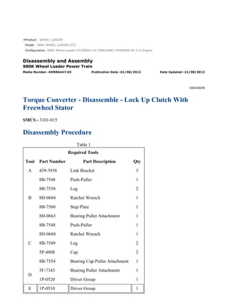
Table 1
Required Tools
Tool Part Number Part Description Qty
A 439-3938 Link Bracket 3
B
8B-7548 Push-Puller 1
8B-7550 Leg 2
8H-0684 Ratchet Wrench 1
8B-7560 Step Plate 1
8H-0663 Bearing Puller Attachment 1
C
8B-7548 Push-Puller 1
8H-0684 Ratchet Wrench 1
8B-7549 Leg 2
5P-4808 Cap 2
8B-7554 Bearing Cup Puller Attachment 1
D
5F-7343 Bearing Puller Attachment 1
1P-0520 Driver Group 1
E 1P-0510 Driver Group 1
1/17(W)
w
2021/12/14
https://127.0.0.1/sisweb/sisweb/techdoc/techdoc_print_page.jsp?returnurl=/sisweb/sis...
2. F 6L-7283 Forcing Bolt
3/8 - 16 by 3 in
7
G 417-1324 Adjust Stand 1
Start By:
a. Separate the torque converter from the transmission and from the output transfer gears.
Illustration 1 g02712129
1. Use Tooling (A) and a suitable lifting device to position the torque converter onto Tooling
(G) and suitable blocking. The weight of the torque converter is approximately 260 kg
(573 lb). Support the torque converter, as shown.
2. Remove bolts (1).
Illustration 2 g02730506
3. Remove relief valve assembly (2A).
2/17(W)
w
2021/12/14
https://127.0.0.1/sisweb/sisweb/techdoc/techdoc_print_page.jsp?returnurl=/sisweb/sis...
3. Illustration 3 g02711758
4. Use Tooling (F) to loosen housing assembly (2) from the torque converter.
5. Use the suitable lifting device and Tooling (A) to remove torque converter housing
assembly (2). The weight of torque converter housing assembly (2) is approximately 144 kg
(317 lb).
Illustration 4 g00871317
6. Remove O-ring seal (3) from torque converter housing assembly (2).
Illustration 5 g00871318
3/17(W)
w
2021/12/14
https://127.0.0.1/sisweb/sisweb/techdoc/techdoc_print_page.jsp?returnurl=/sisweb/sis...
4. 7. Remove bolts (4) from pump adapter (5) and torque converter housing assembly (2).
Illustration 6 g00871264
8. Use Tooling (F) to remove pump adapter (5) from torque converter housing assembly (2).
Illustration 7 g00871319
9. Use Tooling (B) to remove bearing cup (6). Remove bearing cup (6), O-ring seal (8), and
shims (7) from pump adapter (5). See illustration 14 for Tooling (C).
Illustration 8 g00871326
10. Remove pump drive gear (9) from torque converter housing assembly (2).
4/17(W)
w
2021/12/14
https://127.0.0.1/sisweb/sisweb/techdoc/techdoc_print_page.jsp?returnurl=/sisweb/sis...
5. Illustration 9 g00871451
11. Use Tooling (C) to remove bearing cones (10) from each side of pump drive gear (9).
Remove bearing cones (10).
Illustration 10 g00871333
12. Use Tooling (C) to remove bearing cup (11) from torque converter housing assembly (2).
See illustration 14 for Tooling (C).
Illustration 11 g01112900
13. Remove bolt (12) and the washer from torque converter housing assembly (2).
5/17(W)
w
2021/12/14
https://127.0.0.1/sisweb/sisweb/techdoc/techdoc_print_page.jsp?returnurl=/sisweb/sis...
6. 14. Use Tooling (F) to push shaft assembly (14) out of torque converter housing assembly (2).
15. Remove idler gear (13) from torque converter housing assembly (2).
Illustration 12 g01112903
16. Remove O-ring seal (15) from shaft assembly (14).
Illustration 13 g00871365
17. Remove bearing cone (16), bearing cone spacer (17), and bearing cone (18) from idler gear
(13).
6/17(W)
w
2021/12/14
https://127.0.0.1/sisweb/sisweb/techdoc/techdoc_print_page.jsp?returnurl=/sisweb/sis...
7. Illustration 14 g00871366
18. Use Tooling (C) to remove bearing cup (19) from idler gear (13). Remove bearing cup (19).
Illustration 15 g00871367
19. Remove bearing cup spacer (20) from idler gear (13).
Illustration 16 g00871368
7/17(W)
w
2021/12/14
https://127.0.0.1/sisweb/sisweb/techdoc/techdoc_print_page.jsp?returnurl=/sisweb/sis...
8. 20. Remove retaining ring (21) from idler gear (13).
Illustration 17 g00871369
21. Use Tooling (C) to remove bearing cup (22) from idler gear (13). Remove bearing cup (22).
Illustration 18 g00871370
22. Remove studs (23) from torque converter housing assembly (2).
8/17(W)
w
2021/12/14
https://127.0.0.1/sisweb/sisweb/techdoc/techdoc_print_page.jsp?returnurl=/sisweb/sis...
9. Illustration 19 g02729366
23. Remove bolts (24) and gear (25).
Illustration 20 g02735357
24. Use the driver group from Tooling (D) and a suitable press to remove race (25A) from gear
(25).
Illustration 21 g02730012
25. Use a suitable lifting device to reposition the torque converter, as shown. The weight of the
torque converter is approximately 122 kg (269 lb). Remove bolts (26).
9/17(W)
w
2021/12/14
https://127.0.0.1/sisweb/sisweb/techdoc/techdoc_print_page.jsp?returnurl=/sisweb/sis...
10. Illustration 22 g02730687
26. Use Tooling (F) to separate housing (27) from the torque converter.
Illustration 23 g02730689
27. Use two people to remove housing (27). The weight of housing (27) is approximately 26 kg
(57 lb). Remove housing (27), piston (28), and plate (30). Remove seals (29) from piston
(28).
Illustration 24 g02731059
28. Remove bushing (31) from housing (27).
10/17(W)
w
2021/12/14
https://127.0.0.1/sisweb/sisweb/techdoc/techdoc_print_page.jsp?returnurl=/sisweb/sis...
11. Illustration 25 g02731623
29. Remove plate (32), disk (33), races (34), and bearing (35).
Note: Note the orientation of the bearing and races for assembly purposes.
Illustration 26 g02731644
30. Remove bolts (36), coupling assembly (37), and plate (38).
11/17(W)
w
2021/12/14
https://127.0.0.1/sisweb/sisweb/techdoc/techdoc_print_page.jsp?returnurl=/sisweb/sis...
12. Illustration 27 g02731651
31. Use suitable blocking to support the bottom of shaft assembly (39). Remove retaining ring
(40) and plate (41). Shaft assembly (39) can be lowered to the work bench.
Illustration 28 g02731711
Illustration 29 g02732048
12/17(W)
w
2021/12/14
https://127.0.0.1/sisweb/sisweb/techdoc/techdoc_print_page.jsp?returnurl=/sisweb/sis...
13. 32. Install two of bolts (36) and remove turbine (42).
33. Remove bolts (36) and remove hub (43) from turbine (42).
Illustration 30 g02731732
Illustration 31 g02731802
34. Remove race (44) and bearing (45).
Note: Note the orientation of the race and bearing for assembly purposes.
35. Remove stator assembly (46).
13/17(W)
w
2021/12/14
https://127.0.0.1/sisweb/sisweb/techdoc/techdoc_print_page.jsp?returnurl=/sisweb/sis...
14. Illustration 32 g02731806
36. Remove retaining ring (47), plate (48), freewheel springs (49), freewheel rollers (50), and
freewheel cam (51). Remove plate (52) and retaining ring (53) (not shown) from stator (46).
Illustration 33 g02732255
37. Attach Tooling (A) and a suitable lifting device to impeller (54). The weightof impeller (54)
is approximately 27 kg (60 lb).
38. Remove impeller (54) from shaft assembly (39).
Illustration 34 g02735333
39. Position impeller (54) onto suitable blocking, as shown.
14/17(W)
w
2021/12/14
https://127.0.0.1/sisweb/sisweb/techdoc/techdoc_print_page.jsp?returnurl=/sisweb/sis...
15. Illustration 35 g02734776
40. Remove retaining ring (56) and hub (55).
Illustration 36 g02735372
41. Remove seal ring (56).
Illustration 37 g02734816
42. Use Tooling (D) and a suitable press to remove bearing (57).
Illustration 38 g02735374
15/17(W)
w
2021/12/14
https://127.0.0.1/sisweb/sisweb/techdoc/techdoc_print_page.jsp?returnurl=/sisweb/sis...
16. 43. Remove retaining ring (59) and carrier assembly (58) from impeller (54).
Illustration 39 g02735380
44. Remove bearing (60).
Note: Note the orientation of the bearing (60) for assembly purposes.
Illustration 40 g02735387
45. Remove bolts (61), hub (62), and adapter (63) from impeller (54).
16/17(W)
w
2021/12/14
https://127.0.0.1/sisweb/sisweb/techdoc/techdoc_print_page.jsp?returnurl=/sisweb/sis...
18. Product: WHEEL LOADER
Model: 980K WHEEL LOADER GTZ
Configuration: 980K Wheel Loader GTZ00001-UP (MACHINE) POWERED BY C13 Engine
Disassembly and Assembly
980K Wheel Loader Power Train
Media Number -KENR6447-03 Publication Date -01/08/2012 Date Updated -21/08/2012
i06806533
Torque Converter - Assemble - Lock Up Clutch with
Freewheel Stator
SMCS - 3101-016
Assembly Procedure
Table 1
Required Tools
Tool Part Number Part Description Qty
A 138-7573 Link Bracket 3
G
8T-5096 Dial Indicator Test Group 1
5P-2390 Gauge Tool Group 1
H 1P-0520 Driver Group 1
J -
Guide Stud
(3/8 - 16 by 8 in)
2
K -
Guide Stud
(1/2 - 13 by 3 in)
3
L 2P-8312 Retaining Ring Pliers 1
Note: Cleanliness is an important factor. Before assembly, all parts should be thoroughly cleaned
in cleaning fluid. Allow the parts to air dry. Wiping cloths or rags should not be used to dry parts.
Lint may be deposited on the parts which may cause later trouble. Inspect all parts. If any parts are
worn or damaged, use new parts for replacement.
Note: Apply oil to all of the bearings before assembly.
1/18(W)
w
2021/12/14
https://127.0.0.1/sisweb/sisweb/techdoc/techdoc_print_page.jsp?returnurl=/sisweb/sis...
19. Illustration 1 g02735387
1. Install adapter (63), hub (62), and bolts (61) onto impeller (54). Tighten bolts (61) to a
torque or 105 ± 14 N·m (77 ± 10 lb ft).
Illustration 2 g02735380
2. Install bearing (60).
Illustration 3 g02735374
3. Install carrier assembly (58) and retaining ring (59) onto impeller (54).
2/18(W)
w
2021/12/14
https://127.0.0.1/sisweb/sisweb/techdoc/techdoc_print_page.jsp?returnurl=/sisweb/sis...
20. Illustration 4 g06122365
4. Raise the temperature of bearing (57). Install bearing (57) onto hub (55).
5. Install retaining ring (56A) and seal ring (56).
Illustration 5 g02734776
Illustration 6 g02735333
6. Install hub (55) and retaining ring (56) onto impeller (54).
3/18(W)
w
2021/12/14
https://127.0.0.1/sisweb/sisweb/techdoc/techdoc_print_page.jsp?returnurl=/sisweb/sis...
21. Illustration 7 g02752296
7. Install seals (64).
Illustration 8 g02732255
8. Attach Tooling (A) and a suitable lifting device to impeller (54). The weightof impeller (54)
is approximately 27 kg (60 lb).
9. Position impeller (54) onto shaft assembly (39).
Illustration 9 g02731806
4/18(W)
w
2021/12/14
https://127.0.0.1/sisweb/sisweb/techdoc/techdoc_print_page.jsp?returnurl=/sisweb/sis...
22. Illustration 10 g06122374
Typical Example
10. Install retaining ring (53) (not shown) and plate (52) onto stator (46).
11. Install freewheel cam (51), freewheel rollers (50), and springs (49).
Note: Springs (49) must be installed with the maximum number or loops to the outside.
12. Install plate (48) and retaining ring (47).
Illustration 11 g02731802
Illustration 12 g06122399
5/18(W)
w
2021/12/14
https://127.0.0.1/sisweb/sisweb/techdoc/techdoc_print_page.jsp?returnurl=/sisweb/sis...
23. 13. Install stator assembly (46).
14. Install bearing (45) race (44), and outer race (44A).
Illustration 13 g02744699
Illustration 14 g06122404
15. Install hub (43) and turbine (42).
16. Use two of bolts (36) to align the holes.
17. Use suitable blocking to support the bottom of shaft assembly (39). Install plate
(41),retaining ring (40), and ring seal (39A).
6/18(W)
w
2021/12/14
https://127.0.0.1/sisweb/sisweb/techdoc/techdoc_print_page.jsp?returnurl=/sisweb/sis...
24. Illustration 15 g06122416
18. Install springs (36A) and (36B) inside of springs (36). Install springs (36) in an alternating
pattern. An example would be to install a spring (36) with a spring (36A) inside. The next
one would be to install a spring (36) with a spring (36B) inside.
Illustration 16 g06122422
19. Install plate (38), coupling assembly (37), and bolts (36). Tighten bolts (36) to a torque of
60 ± 7 N·m (44 ± 5 lb ft).
Note: Plate (38) has an O-ring groove that is not used.
7/18(W)
w
2021/12/14
https://127.0.0.1/sisweb/sisweb/techdoc/techdoc_print_page.jsp?returnurl=/sisweb/sis...
25. Illustration 17 g06122434
20. Install disk (33), races (34), and bearing (35).
Illustration 18 g02731059
21. Lower the temperature of bushing (31). Install bushing (31) into housing (27).
8/18(W)
w
2021/12/14
https://127.0.0.1/sisweb/sisweb/techdoc/techdoc_print_page.jsp?returnurl=/sisweb/sis...
26. Illustration 19 g02730689
22. Install seals (29) onto piston (28). Install plate (30), piston (28), and housing (27).
Note: Plate (30) has an O-ring groove that is not used.
Illustration 20 g02730012
23. Tighten bolts (26). Tighten bolts (36) to a torque of 60 ± 7 N·m (44 ± 5 lb ft).
9/18(W)
w
2021/12/14
https://127.0.0.1/sisweb/sisweb/techdoc/techdoc_print_page.jsp?returnurl=/sisweb/sis...
27. Illustration 21 g02735357
24. Lower the temperature of race (25A). If necessary, use the driver group from Tooling (D)
and a suitable press to install race (25A) into gear (25).
Illustration 22 g02729366
25. Use a suitable lifting devise to reposition the torque converter, as shown. The weight of the
torque converter is approximately 1157 N (260 lb).
26. Install drive gear (25) and bolts (24). Tighten the bolts to a torque of 50 ± 7 N·m
(37 ± 5 lb ft).
Illustration 23 g00872709
27. Install studs (23) in torque converter housing assembly (2). Tighten the studs to a torque of
100 ± 15 N·m (74 ± 11 lb ft).
10/18(W)
w
2021/12/14
https://127.0.0.1/sisweb/sisweb/techdoc/techdoc_print_page.jsp?returnurl=/sisweb/sis...
28. Suggest:
If the above button click is invalid.
Please download this document
first, and then click the above link
to download the complete manual.
Thank you so much for reading
29. Illustration 24 g00872711
28. Install retaining ring (21) in the groove of idler gear (13).
Illustration 25 g00872713
29. Use the proper equipment to handle bearing cup (22). Lower the temperature of bearing cup
(22). Install bearing cup (22) in idler gear (13).
Illustration 26 g00872715
30. Flip idler gear (13) to the opposite side. Install bearing cup spacer (20) in idler gear (13).
The notch in bearing cup spacer (20) must be aligned with retaining ring (21).
11/18(W)
w
2021/12/14
https://127.0.0.1/sisweb/sisweb/techdoc/techdoc_print_page.jsp?returnurl=/sisweb/sis...