
Recommended
More Related Content
Similar to Caterpillar Cat 953 TRACK LOADER (Prefix 20Z) Service Repair Manual (20Z00001-00266).pdf
Similar to Caterpillar Cat 953 TRACK LOADER (Prefix 20Z) Service Repair Manual (20Z00001-00266).pdf (17)
More from fjkskkedmm4r
More from fjkskkedmm4r (20)
Recently uploaded
Recently uploaded (20)
Caterpillar Cat 953 TRACK LOADER (Prefix 20Z) Service Repair Manual (20Z00001-00266).pdf
- 1. Shutdown SIS Previous Screen Product: TRACK LOADER Model: 953 TRACK LOADER 20Z Configuration: 953 LGP TRACK LOADER / HIGH DRIVE / 20Z00001-00266 (MACHINE) POWERED BY 3204 ENGINE Disassembly and Assembly 3204 VEHICULAR ENGINE FOR 943 & 953 TRACK-TYPE LOADERS Media Number -SENR4214-00 Publication Date -01/04/1985 Date Updated -11/10/2001 Governor (New Scroll Fuel System Effective In Production With 10X5411-Up, 45V36536-Up) SMCS - 1264-015; 1264-016 1/19 953 LGP TRACK LOADER / HIGH DRIVE / 20Z00001-00266 (MACHINE) POWE... 2022/1/5 https://127.0.0.1/sisweb/sisweb/techdoc/techdoc_print_page.jsp?returnurl=/sisw...
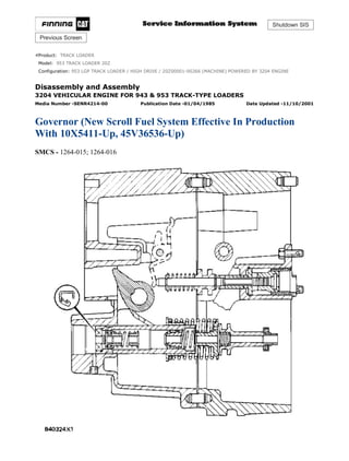
- 2. Disassemble Governor (New Scroll Fuel System Effective In Production With 10X5411-Up, 45V36536-Up) START BY: a. remove fuel injection pump housing and governor (new scroll fuel system effective in production with 10X5411-UP, 45V36536-UP) b. remove fuel transfer pump (new scroll fuel system effective in production with 10X5411-UP, 45V36536-UP) NOTE: If it is desired to remove only the governor so the fuel injection pump housing can be disassembled, do only Steps 1, 2, 15, 21, 25, 26, 27, 28, 31, 33, 34 and 37. 1. Remove bolts (1) and cover (2). 2/19 953 LGP TRACK LOADER / HIGH DRIVE / 20Z00001-00266 (MACHINE) POWE... 2022/1/5 https://127.0.0.1/sisweb/sisweb/techdoc/techdoc_print_page.jsp?returnurl=/sisw...
- 3. 2. Remove six bolts (3), two top bolts (4), housing (5) and the gasket. 3. Remove governor spring (6), the two wave washers, one flatwasher and seat from the guide in the housing. 4. Make a mark of the position of lever (7) on shaft (8). Loosen bolt (10). Use a chisel or screwdriver to expand expansion of lever (7) so it can be removed from shaft (8). 5. Remove cover assembly (9). 6. Use tooling (A) to remove seal (10) from cover (9). 7. Remove low idle adjustment screw (12) and spring (11) from the housing. 3/19 953 LGP TRACK LOADER / HIGH DRIVE / 20Z00001-00266 (MACHINE) POWE... 2022/1/5 https://127.0.0.1/sisweb/sisweb/techdoc/techdoc_print_page.jsp?returnurl=/sisw...
- 4. 8. Remove shaft assembly (14), lever (13) and lever (15) from the housing. 9. Remove two snap rings from pins (17), and remove pins (17). Remove plates (16) and stop (18) from the shaft assembly. 10. Remove pin (20), pin (19) and spring (21) from the shaft assembly. 11. Remove shaft (22) and lever (23) from the housing. 4/19 953 LGP TRACK LOADER / HIGH DRIVE / 20Z00001-00266 (MACHINE) POWE... 2022/1/5 https://127.0.0.1/sisweb/sisweb/techdoc/techdoc_print_page.jsp?returnurl=/sisw...
- 5. NOTICE Remove check valve (24) only if a replacement is necessary because the check valve will be damaged during removal. 12. Remove check valve (24) if a replacement is necessary. 13. Remove contact (25) and body (26) for the governor dashpot adjustment screw from the housing. Remove bolts (27), cover (28) and the gasket from the housing. 14. Remove seal (29) and adjustment screw (30) for high idle. 15. Remove two bolts (31), housing (32) and the gasket from the fuel injection pump housing. 5/19 953 LGP TRACK LOADER / HIGH DRIVE / 20Z00001-00266 (MACHINE) POWE... 2022/1/5 https://127.0.0.1/sisweb/sisweb/techdoc/techdoc_print_page.jsp?returnurl=/sisw...
- 6. 16. Remove bolts (33) and torque control group (34). 17. Disassemble the torque control group and inspect the spacer, spring and insulator for damage or wear. 18. Remove bolts (36) and block (35) for the full load stop from the housing. 19. Remove the bolt that holds collar (37) to bolt (39). Remove collar (37) and spring (38) from bolt (39). Remove bolt (39) from the block. 20. Remove the stop screw from collar (37) if a replacement is necessary. 21. Remove bolts (41) and governor servo (40) from the fuel injection pump. 6/19 953 LGP TRACK LOADER / HIGH DRIVE / 20Z00001-00266 (MACHINE) POWE... 2022/1/5 https://127.0.0.1/sisweb/sisweb/techdoc/techdoc_print_page.jsp?returnurl=/sisw...
- 7. 22. Remove lockring (46), seat (45), spring (broken link spring) (44) and sleeve (43) from valve (42). Remove the other lockring (46) from the groove in the center of valve (42). NOTE: The groove in the bottom of valve (42) must be in alignment with the servo body to permit removal from the fuel rack. 23. Remove valve (42), sleeve (47) and piston (49) from the governor servo. Remove the O-ring seal from sleeve (47). 24. Remove pin (48) and lever (50) from the governor servo. 25. Use tool (C) to hold spring (52) in compression so ring (51) can be removed. Spring (52) is used to put a preload on the thrust bearing for the camshaft in the fuel injection pump housing. 26. Remove ring (51); then remove tool (C). 27. Remove bearing (53), sleeves (54) and spring (52) from the governor shaft. 7/19 953 LGP TRACK LOADER / HIGH DRIVE / 20Z00001-00266 (MACHINE) POWE... 2022/1/5 https://127.0.0.1/sisweb/sisweb/techdoc/techdoc_print_page.jsp?returnurl=/sisw...
- 8. 28. Remove ring (55) and dashpot assembly (56) from the governor shaft. 29. Use tool (B) to remove snap ring (62) from seat (59). Remove ring (61) and spool (60) from seat (59). 30. Remove seat (59) from spring (58), and remove spring (58) from seat (57). 31. Remove spring (overfueling spring) (63) and riser (64) from the governor shaft. 32. Remove ring (65), races (66) and bearing (67) from the riser. 8/19 953 LGP TRACK LOADER / HIGH DRIVE / 20Z00001-00266 (MACHINE) POWE... 2022/1/5 https://127.0.0.1/sisweb/sisweb/techdoc/techdoc_print_page.jsp?returnurl=/sisw...
- 9. 33. Use a screwdriver to remove shield (68) as shown. NOTE: Make a replacement of shield (68) any time it is removed. 34. Remove bolts (69) and carrier (70) for the governor flyweights. 35. Remove dowels (71) and flyweights (73) from the carrier. 36. Remove shaft (72) from the carrier. Remove the dowel from shaft (72). 37. Remove races (74) and bearing (75) from the camshaft in the fuel injection pump housing. Assemble Governor (New Scroll Fuel System Effective In Production With 10Y5411-UP, 45V36536-UP) 9/19 953 LGP TRACK LOADER / HIGH DRIVE / 20Z00001-00266 (MACHINE) POWE... 2022/1/5 https://127.0.0.1/sisweb/sisweb/techdoc/techdoc_print_page.jsp?returnurl=/sisw...
- 10. NOTE: If the governor was removed only to permit repair of the fuel injection pump housing, do only Steps 1, 4, 5, 7, 9, 10, 11, 16, 22, 37, 39 and 40. NOTE: Put clean oil on all parts before assembly. Be sure all oil passages are clear. 1. Install one race (1), bearing (2) and the other race (1) on the camshaft in the fuel injection pump housing. 2. Put flyweights (3) in position on carrier (4), and install the dowels to hold the flyweights in place. The flyweights must move freely on the dowels and have 0.010 to 0.23 mm (0.0004 to 0.009 in.) end play. 10/19 953 LGP TRACK LOADER / HIGH DRIVE / 20Z00001-00266 (MACHINE) PO... 2022/1/5 https://127.0.0.1/sisweb/sisweb/techdoc/techdoc_print_page.jsp?returnurl=/sisw...
- 11. 3. Install dowel (5) in governor shaft (6), and install the governor shaft in the carrier as shown. 4. Put the carrier in position on the camshaft, and install the bolts that hold the carrier in place. NOTE: Make a replacement of shield (7) any time it is removed. 5. Install shield (7) on the carrier, and use tool (A) to push the shield against its seat. Use a hammer and punch to move the metal (stake) two places on the side of the shield 180° ± 5° apart next to the holes in the shield. 6. Install one race (9), bearing (10), the other race (9), and use tool (B) to install the ring on riser (8) as shown. 11/19 953 LGP TRACK LOADER / HIGH DRIVE / 20Z00001-00266 (MACHINE) PO... 2022/1/5 https://127.0.0.1/sisweb/sisweb/techdoc/techdoc_print_page.jsp?returnurl=/sisw...
- 12. 7. Install riser (8) and the spring (overfueling spring) on the governor shaft as shown. 8. Assemble the dashpot as follows: a. Install spring (12) on seat (11), and install seat (13) in spring (12). b. Put spool (14) and ring (15) in position on seat (13), and use tool (B) to install stop ring (16) to hold them in place. 9. Install dashpot assembly (17) on the governor shaft as shown. 10. Install ring (21) in the lower groove in the governor shaft. Install one sleeve (20), spring (19), the other sleeve (20) and bearing (18) on the governor shaft as shown. NOTE: Spring (19) is used to put a preload on the thrust bearing on the camshaft in the fuel injection pump housing. 12/19 953 LGP TRACK LOADER / HIGH DRIVE / 20Z00001-00266 (MACHINE) PO... 2022/1/5 https://127.0.0.1/sisweb/sisweb/techdoc/techdoc_print_page.jsp?returnurl=/sisw...
- 13. 11. Use tool (C) to hold spring (19) in compression, and install ring (22) in the groove in the governor shaft. Remove tool (C). 12. Put lever (27) in position on governor servo (23), and install pin (24) to hold the lever in place. Use a hammer and chisel to move the metal (stake) four places 90° apart on the outside surface on both legs of the governor servo to hold pin (24) in place. 13. Install the O-ring seal on sleeve (25). Install piston (26) and sleeve (25) in the governor servo as shown. 14. Install valve (28) in the governor servo as shown. 15. Install one lockring (32) in the groove near the center of valve (28). Put sleeve (29), spring (broken link spring) (30) and seat (31) in position on valve (28), and install the other lockring (32) to hold them in place. 13/19 953 LGP TRACK LOADER / HIGH DRIVE / 20Z00001-00266 (MACHINE) PO... 2022/1/5 https://127.0.0.1/sisweb/sisweb/techdoc/techdoc_print_page.jsp?returnurl=/sisw...
- 14. 16. Put the governor servo in position on the fuel injection pump housing with piston (26) engaged over rack (33), and install the bolts that hold the governor servo in place. 17. Install torque rise adjustment screw (36) in collar (34) as shown, and install locknut (35) on the screw. 18. Install bolt (38) in block (40) as shown. Install spring (37) on bolt (38) as shown. Put collar (34) in position on bolt (38) with the hole in the collar in alignment with the notch in bolt (38), and install bolt (39) to hold the collar in place. 19. Put block (40) in position on housing (41) with the holes in the block in alignment with dowels (42). Install the bolts that hold the block in place. 14/19 953 LGP TRACK LOADER / HIGH DRIVE / 20Z00001-00266 (MACHINE) PO... 2022/1/5 https://127.0.0.1/sisweb/sisweb/techdoc/techdoc_print_page.jsp?returnurl=/sisw...
- 15. 20. Assemble the torque control group as follows: a. Install bar (47), contact (44), spacer (48) on insulator (43) as shown. b. Install retainer (46), bar (49) and the insulator assembly on bolts (45) as shown. 21. Install torque control group (50) on block (40) as shown. If housing (41) is installed with the flange on bolt (38) on the wrong side of the dashpot, the riser in the governor will be held in the maximum fuel delivery position. To prevent possible personal injury, make sure housing (41) is installed on the fuel injection pump housing with the flange on bolt (38) behind the dashpot. 22. Install gasket (51) on the fuel injection pump housing. Put housing (41) in position on the fuel injection pump housing with bolt (38) behind the dashpot as shown. Install the bolts that hold housing (41) in place. 15/19 953 LGP TRACK LOADER / HIGH DRIVE / 20Z00001-00266 (MACHINE) PO... 2022/1/5 https://127.0.0.1/sisweb/sisweb/techdoc/techdoc_print_page.jsp?returnurl=/sisw...
- 16. 23. Use tooling (D) to install lip-type seal (52) in the governor outer housing with the lip in as shown. 24. Install adjustment screw (53) and the locknut for the high idle adjustment. 25. Make a replacement of screen assembly (54) and seal for fuel ratio control. 26. Install an O-ring seal on body (56) for the dashpot adjustment, and install the body in the housing. 27. Install gasket and cover (57) on the housing. 28. Install contact (55) in the housing, and tighten to a torque of 4.5 ± 0.6 N·m (40 ± 5 lb.in.). 29. Install check valve (58) in the housing as shown. 16/19 953 LGP TRACK LOADER / HIGH DRIVE / 20Z00001-00266 (MACHINE) PO... 2022/1/5 https://127.0.0.1/sisweb/sisweb/techdoc/techdoc_print_page.jsp?returnurl=/sisw...
- 17. 30. Put lever (59) in position in the housing as shown, and install shaft (60) to hold the lever in place. 31. Install spring (63) in shaft assembly (64). Install pin (61) in shaft assembly (64) with the tip of the pin engaged in the hole in spring (63). Install pin (62) in the shaft assembly to hold pin (61) in place. 32. Put stop (67) and plates (65) in position on shaft assembly (64), and install pins (66) to hold the plates and stop in place. Install snap rings (68) to hold pins (66) in place. 33. Put levers (69) and (70) in position in the housing as shown, and install shaft assembly (64) to hold the levers in place. 34. Install adjustment screw (71) and the locknut for the low idle adjustment in the housing. Install spring (72) in the hole in the shaft assembly and in the housing. 17/19 953 LGP TRACK LOADER / HIGH DRIVE / 20Z00001-00266 (MACHINE) PO... 2022/1/5 https://127.0.0.1/sisweb/sisweb/techdoc/techdoc_print_page.jsp?returnurl=/sisw...
- 18. 35. Use tooling (D) to install the lip-type seal in cover (73) with the lip in as shown. 36. Put the gasket and cover (73) in position on the housing, and install the bolts that hold it in place. NOTE: Make sure the seal, washers and spring are on top of the lever as shown. These parts must be kept in this position when housing (79) is put in position on the inner governor housing. NOTICE Flat washer (77) must be installed between wave washers (76). 37. Install the governor spring assembly on guide (75) as follows: Install seat (78), one wave washer (76), flat washer (77), the other wave washer (76) and spring (74) on guide (75) as shown. 18/19 953 LGP TRACK LOADER / HIGH DRIVE / 20Z00001-00266 (MACHINE) PO... 2022/1/5 https://127.0.0.1/sisweb/sisweb/techdoc/techdoc_print_page.jsp?returnurl=/sisw...
- 19. 38. Put the gasket and housing (79) in position on the inner governor housing, and install the nine bolts that hold it in place. 39. Install governor control lever (80). 40. Install O-ring seals (81) and cover (82). 41. Make governor adjustments. See Governor Adjustments in Testing And Adjusting. END BY: a. install fuel injection pump housing and governor (new scroll fuel system effective in production with 10X5411-UP, 45V36536-UP) b. install fuel transfer pump (new scroll fuel system effective in production with 10X5411-UP, 45V36536-UP) Copyright 1993 - 2022 Caterpillar Inc. All Rights Reserved. Private Network For SIS Licensees. Wed Jan 5 21:17:10 UTC+0800 2022 19/19 953 LGP TRACK LOADER / HIGH DRIVE / 20Z00001-00266 (MACHINE) PO... 2022/1/5 https://127.0.0.1/sisweb/sisweb/techdoc/techdoc_print_page.jsp?returnurl=/sisw...
- 20. Shutdown SIS Previous Screen Product: TRACK LOADER Model: 953 TRACK LOADER 20Z Configuration: 953 LGP TRACK LOADER / HIGH DRIVE / 20Z00001-00266 (MACHINE) POWERED BY 3204 ENGINE Disassembly and Assembly 3204 VEHICULAR ENGINE FOR 943 & 953 TRACK-TYPE LOADERS Media Number -SENR4214-00 Publication Date -01/04/1985 Date Updated -11/10/2001 Fuel Injection Pumps (Interim Scroll Fuel System) SMCS - 1251-015; 1251-016; 1251-011; 1251-012 Remove Fuel Injection Pumps (Interim Scroll Fuel System) START BY: a. disassemble governor (interim scroll fuel system) 1/7 953 LGP TRACK LOADER / HIGH DRIVE / 20Z00001-00266 (MACHINE) POWE... 2022/1/5 https://127.0.0.1/sisweb/sisweb/techdoc/techdoc_print_page.jsp?returnurl=/sisw...
- 21. 1. Remove plug (2) from the fuel injection pump housing. 2. Pull rack (1) toward the governor end of the fuel injection pump housing. Install tool (B) in the pump housing. Hold tool (B) in against the rack, and push the rack back toward the drive end of the pump housing until the notch in the rack comes in contact with tool (B). The rack is now in the center position. Install clip (3) [part of tooling (A)] to hold the rack in the center position against tool (B). NOTICE The rack must be in the center (zero) position before the fuel injection pumps can be removed. Make a note of the location of each fuel injection pump so it can be installed in its original location in the pump housing. 3. Remove the cap and soft washer from the top of the fuel injection pump. 4. Install tool (C), and remove bushing (4) and the O-ring seal below the bushing. 2/7 953 LGP TRACK LOADER / HIGH DRIVE / 20Z00001-00266 (MACHINE) POWE... 2022/1/5 https://127.0.0.1/sisweb/sisweb/techdoc/techdoc_print_page.jsp?returnurl=/sisw...
- 22. 5. Install tool (D) on bonnet (5) of the fuel injection pump, and remove the fuel injection pump from the pump housing. Install Fuel Injection Pumps (Interim Scroll Fuel System) NOTICE The rack must be in the center (zero) position before the fuel injection pumps can be installed. See Step 2 of the fuel injection pump removal procedure to put the rack in the center position. 3/7 953 LGP TRACK LOADER / HIGH DRIVE / 20Z00001-00266 (MACHINE) POWE... 2022/1/5 https://127.0.0.1/sisweb/sisweb/techdoc/techdoc_print_page.jsp?returnurl=/sisw...
- 23. 1. With the rack in the center position, install the fuel injection pumps as follows: a. Turn the camshaft until the lobe of the camshaft is down for the pump to be installed. b. Install tool (D) on the pump. c. Put groove (1) in the barrel in alignment with groove (2) in the pump gear segment. Put the pump in position so the grooves are in alignment with the guide pins in the housing and lifter. Install the pump in its correct position in the housing. d. Install the O-ring seal and bushing (3) over the bonnet. Install tool (C) on the bonnet, and push down on tool (D). Tighten bushing (3) by hand until the bushing is even with the top of the housing. If the installation of the bushing cannot be made this far by hand, remove it. Remove the pump, put the parts in alignment again, and install the bushing again. NOTICE If installation of pump is correct, the bushing can be tightened by hand until it is even with the face of the pump housing. The fuel injection pump, the housing or the lifter will be damaged if force is used to install the bushing until it is even with the face of the pump housing. 4/7 953 LGP TRACK LOADER / HIGH DRIVE / 20Z00001-00266 (MACHINE) POWE... 2022/1/5 https://127.0.0.1/sisweb/sisweb/techdoc/techdoc_print_page.jsp?returnurl=/sisw...
- 24. e. Check the rack travel after each pump is installed as follows: Move the clamp, part of tooling (A), away from the end of the rack, and remove timing pin (B) from the fuel injection pump housing. Install tooling (A) and (E) on the pump housing as shown to measure rack movement. Hold rack (4) against the stem in tool (E) when the measurement is made. The total rack movement must be 20.32 mm (.800 in.). If the rack cannot be moved this distance, the pump gear segment is not in the correct position and the pump must be removed and installed again. 2. After all the fuel injection pumps are installed, remove tooling (A) and (E). Install the plug in the hole for timing pin (B). Use tool (C) to tighten bushing (3) to a torque of 205 ± 14 N·m (150 ± 10 lb.ft.). Remove tool (C). Install the soft washers and protection caps for the fuel injection pumps. 3. After installation of the fuel injection pump housing and governor, adjust the governor and set the rack. See Governor Adjustments And Fuel Rack Setting in Testing And Adjusting. END BY: a. assemble governor (interim scroll fuel system) b. install fuel injection pump housing and governor (interim scroll fuel system) Disassemble Fuel Injection Pumps (Interim Scroll Fuel System) START BY: a. remove fuel injection pumps (interim scroll fuel system) NOTICE Be careful when the fuel injection pumps are disassembled. Do not damage the surfaces of the plungers, barrels and bonnets. Any scratches will cause leakage inside the fuel injection pump. The plunger and barrel for each pump are made as a set. Do not put the plunger of one pump in the barrel of another pump. The check assemblies are made as a set. Do not mix the parts of the different check assemblies. If one part has wear, install a complete new pump assembly. Be careful when the plunger is put into the bore of the barrel. 5/7 953 LGP TRACK LOADER / HIGH DRIVE / 20Z00001-00266 (MACHINE) POWE... 2022/1/5 https://127.0.0.1/sisweb/sisweb/techdoc/techdoc_print_page.jsp?returnurl=/sisw...
- 25. 1. Remove ring (1), and separate bonnet (2) and barrel (3). 2. Remove spring (4), and check assembly (5) from the bonnet. 3. Remove plunger (8) and washer (7) as a unit from spring (6) and the barrel. Remove washer (7) from the plunger. Remove spring (6) from the barrel. NOTICE Do not remove the gear from the plunger. The gear and plunger are assembled and adjusted at the factory. Assemble Fuel Injection Pumps (Interim Scroll Fuel System) NOTICE Put clean fuel oil on all parts during assembly. 6/7 953 LGP TRACK LOADER / HIGH DRIVE / 20Z00001-00266 (MACHINE) POWE... 2022/1/5 https://127.0.0.1/sisweb/sisweb/techdoc/techdoc_print_page.jsp?returnurl=/sisw...
- 26. 1. Install spring (2) on barrel (1). Install washer (3) on plunger (4) with the flat side toward the gear. Install plunger (4) in barrel (1), and engage washer (3) in spring (2). 2. Install spring (5), and check assembly (6) in bonnet (7). NOTICE Do not slide bonnet (7) across the face of barrel (1) when ring (8) is installed. The check assembly in the bonnet can put scratches in the face of barrel (1). 3. Put bonnet (7) in position on barrel (1), and install ring (8) to hold the bonnet and barrel together. END BY: a. install fuel injection pumps (interim scroll fuel system) Copyright 1993 - 2022 Caterpillar Inc. All Rights Reserved. Private Network For SIS Licensees. Wed Jan 5 21:18:06 UTC+0800 2022 7/7 953 LGP TRACK LOADER / HIGH DRIVE / 20Z00001-00266 (MACHINE) POWE... 2022/1/5 https://127.0.0.1/sisweb/sisweb/techdoc/techdoc_print_page.jsp?returnurl=/sisw...
- 27. Please write to us. Our email: aservicemanualpdf@yahoo.com Please go to the homepage to get the full manual, or other brand PDF manuals. Home Site: aservicemanualpdf.com
- 28. Thank you very much for your reading. Please Click Here. Then Get COMPLETE MANUAL. NO WAITING NOTE: If there is no response to click on the link above, please download the PDF document first and then click on it. GET MORE OTHER MANUALS https://www.aservicemanualpdf.com/ GET MORE OTHER MANUALS https://www.aservicemanualpdf.com/
- 29. Shutdown SIS Previous Screen Product: TRACK LOADER Model: 953 TRACK LOADER 20Z Configuration: 953 LGP TRACK LOADER / HIGH DRIVE / 20Z00001-00266 (MACHINE) POWERED BY 3204 ENGINE Disassembly and Assembly 3204 VEHICULAR ENGINE FOR 943 & 953 TRACK-TYPE LOADERS Media Number -SENR4214-00 Publication Date -01/04/1985 Date Updated -11/10/2001 Fuel Injection Pump Housing (Interim Scroll Fuel System) SMCS - 1253-011; 1253-012 Disassemble Fuel Injection Pump Housing (Interim Scroll Fuel System) START BY: a. remove fuel injection pumps (interim scroll fuel system) 1. Remove elbow (1) and the plate (orifice) under the elbow. 1/6 953 LGP TRACK LOADER / HIGH DRIVE / 20Z00001-00266 (MACHINE) POWE... 2022/1/5 https://127.0.0.1/sisweb/sisweb/techdoc/techdoc_print_page.jsp?returnurl=/sisw...
- 30. 2. Remove rack (2) from the fuel injection pump housing. NOTE: Spacers (3) are different thickness and are used to set the injection timing between cylinders. Spacers (3) and lifters (4) must be installed in the same bore in the pump housing from which they are removed. Put identification marks on the spacers and lifters as to their location in the pump housing. 3. Remove spacers (3) and lifters (4) from the pump housing. NOTE: The 943 lifters are made of aluminum. The 953 lifters are made of steel. 4. Remove bolt (5), the lock and plate (6) from the camshaft. 5. Remove spring (7) and gear (8) from the camshaft. 2/6 953 LGP TRACK LOADER / HIGH DRIVE / 20Z00001-00266 (MACHINE) POWE... 2022/1/5 https://127.0.0.1/sisweb/sisweb/techdoc/techdoc_print_page.jsp?returnurl=/sisw...
- 31. 6. Remove camshaft (10) from the pump housing. 7. Remove bearings (9) and (11) from the pump housing. 8. Use tooling (A) as shown to remove the bearings for the camshaft from the pump housing. Assemble Fuel Injection Pump Housing (Interim Scroll Fuel System) NOTE: Be sure all oil passages in the pump housing are clear. Put clean oil on all parts before assembly. 3/6 953 LGP TRACK LOADER / HIGH DRIVE / 20Z00001-00266 (MACHINE) POWE... 2022/1/5 https://127.0.0.1/sisweb/sisweb/techdoc/techdoc_print_page.jsp?returnurl=/sisw...